CN106541397B - Enhanced robotic teaching tool - Google Patents
Enhanced robotic teaching tool Download PDFInfo
- Publication number
- CN106541397B CN106541397B CN201610525664.9A CN201610525664A CN106541397B CN 106541397 B CN106541397 B CN 106541397B CN 201610525664 A CN201610525664 A CN 201610525664A CN 106541397 B CN106541397 B CN 106541397B
- Authority
- CN
- China
- Prior art keywords
- robotic arm
- alignment
- tool
- end effector
- arm
- Prior art date
- Legal status (The legal status is an assumption and is not a legal conclusion. Google has not performed a legal analysis and makes no representation as to the accuracy of the status listed.)
- Active
Links
- 239000012636 effector Substances 0.000 claims abstract description 94
- 238000000034 method Methods 0.000 claims description 29
- 238000006073 displacement reaction Methods 0.000 claims description 13
- 230000003993 interaction Effects 0.000 claims description 7
- 239000003550 marker Substances 0.000 description 8
- 230000007246 mechanism Effects 0.000 description 8
- 230000008569 process Effects 0.000 description 8
- 238000007514 turning Methods 0.000 description 4
- 230000006870 function Effects 0.000 description 3
- 238000004519 manufacturing process Methods 0.000 description 3
- 230000000712 assembly Effects 0.000 description 2
- 238000000429 assembly Methods 0.000 description 2
- 230000000994 depressogenic effect Effects 0.000 description 2
- 238000005516 engineering process Methods 0.000 description 2
- 238000009434 installation Methods 0.000 description 2
- 230000003278 mimic effect Effects 0.000 description 2
- 230000004048 modification Effects 0.000 description 2
- 238000012986 modification Methods 0.000 description 2
- 230000008859 change Effects 0.000 description 1
- 230000006872 improvement Effects 0.000 description 1
- 238000003754 machining Methods 0.000 description 1
- 238000005259 measurement Methods 0.000 description 1
- 230000003252 repetitive effect Effects 0.000 description 1
Images


Classifications
-
- B—PERFORMING OPERATIONS; TRANSPORTING
- B25—HAND TOOLS; PORTABLE POWER-DRIVEN TOOLS; MANIPULATORS
- B25J—MANIPULATORS; CHAMBERS PROVIDED WITH MANIPULATION DEVICES
- B25J9/00—Programme-controlled manipulators
- B25J9/02—Programme-controlled manipulators characterised by movement of the arms, e.g. cartesian coordinate type
- B25J9/04—Programme-controlled manipulators characterised by movement of the arms, e.g. cartesian coordinate type by rotating at least one arm, excluding the head movement itself, e.g. cylindrical coordinate type or polar coordinate type
- B25J9/041—Cylindrical coordinate type
- B25J9/042—Cylindrical coordinate type comprising an articulated arm
-
- B—PERFORMING OPERATIONS; TRANSPORTING
- B25—HAND TOOLS; PORTABLE POWER-DRIVEN TOOLS; MANIPULATORS
- B25J—MANIPULATORS; CHAMBERS PROVIDED WITH MANIPULATION DEVICES
- B25J15/00—Gripping heads and other end effectors
- B25J15/04—Gripping heads and other end effectors with provision for the remote detachment or exchange of the head or parts thereof
-
- B—PERFORMING OPERATIONS; TRANSPORTING
- B25—HAND TOOLS; PORTABLE POWER-DRIVEN TOOLS; MANIPULATORS
- B25J—MANIPULATORS; CHAMBERS PROVIDED WITH MANIPULATION DEVICES
- B25J9/00—Programme-controlled manipulators
- B25J9/10—Programme-controlled manipulators characterised by positioning means for manipulator elements
-
- B—PERFORMING OPERATIONS; TRANSPORTING
- B25—HAND TOOLS; PORTABLE POWER-DRIVEN TOOLS; MANIPULATORS
- B25J—MANIPULATORS; CHAMBERS PROVIDED WITH MANIPULATION DEVICES
- B25J9/00—Programme-controlled manipulators
- B25J9/16—Programme controls
- B25J9/1679—Programme controls characterised by the tasks executed
- B25J9/1692—Calibration of manipulator
-
- B—PERFORMING OPERATIONS; TRANSPORTING
- B25—HAND TOOLS; PORTABLE POWER-DRIVEN TOOLS; MANIPULATORS
- B25J—MANIPULATORS; CHAMBERS PROVIDED WITH MANIPULATION DEVICES
- B25J9/00—Programme-controlled manipulators
- B25J9/16—Programme controls
- B25J9/1694—Programme controls characterised by use of sensors other than normal servo-feedback from position, speed or acceleration sensors, perception control, multi-sensor controlled systems, sensor fusion
-
- G—PHYSICS
- G05—CONTROLLING; REGULATING
- G05B—CONTROL OR REGULATING SYSTEMS IN GENERAL; FUNCTIONAL ELEMENTS OF SUCH SYSTEMS; MONITORING OR TESTING ARRANGEMENTS FOR SUCH SYSTEMS OR ELEMENTS
- G05B2219/00—Program-control systems
- G05B2219/30—Nc systems
- G05B2219/39—Robotics, robotics to robotics hand
- G05B2219/39015—With different manipulator configurations, contact known sphere, ballbar
-
- G—PHYSICS
- G05—CONTROLLING; REGULATING
- G05B—CONTROL OR REGULATING SYSTEMS IN GENERAL; FUNCTIONAL ELEMENTS OF SUCH SYSTEMS; MONITORING OR TESTING ARRANGEMENTS FOR SUCH SYSTEMS OR ELEMENTS
- G05B2219/00—Program-control systems
- G05B2219/30—Nc systems
- G05B2219/39—Robotics, robotics to robotics hand
- G05B2219/39468—Changeable hand, tool, code carrier, detector
-
- G—PHYSICS
- G05—CONTROLLING; REGULATING
- G05B—CONTROL OR REGULATING SYSTEMS IN GENERAL; FUNCTIONAL ELEMENTS OF SUCH SYSTEMS; MONITORING OR TESTING ARRANGEMENTS FOR SUCH SYSTEMS OR ELEMENTS
- G05B2219/00—Program-control systems
- G05B2219/30—Nc systems
- G05B2219/39—Robotics, robotics to robotics hand
- G05B2219/39515—Grapple object, grip in compliant mode, self alignment of fingers and object
Abstract
An apparatus (118) for aligning a robotic arm (104) with an end effector (112) is provided. The device (118) may include a ball tool (134) and a receiver (132). The ball tool (134) may include a ball end portion (140) and a distal base portion (142) configured to be detachably coupled to the end effector (112). The receiver (132) may include a plurality of arms (138) and a proximal base portion (136) configured to be detachably coupled to the robotic arm (104). Further, the arm (138) may be configured to receive the spherical end portion (140) and include one or more indicators (160), the indicators (160) configured to track alignment between the robotic arm (104) and the end effector (112).
Description
Technical Field
The present disclosure relates generally to robotic assemblies and, more particularly, to apparatus, systems, and methods for aligning a robotic arm with an end effector.
Background
Robotic assemblies such as robotic arms are commonly used for a variety of industrial applications. Automated repetitive functions such as measuring, manufacturing, positioning, assembling parts, and the like, as well as other functions, may be performed using the robotic arm, which may otherwise be cumbersome or more difficult to manually implement by hand. Such automated processing not only reduces the amount of machining involved and potential human error, but also increases overall productivity and allows more flexibility in performing tasks. In aircraft manufacturing applications, for example, the robotic arms may be preprogrammed with algorithms and data that not only enable the automated installation of a variety of different aircraft components, but that can be easily reconfigured to accommodate specific changes in the automated process.
Robotic arms are often configured with a working end that may be fitted with a variety of replaceable end effectors or tools designed for different tasks. More particularly, the working end may be provided with a universal connector that uses a detachable mechanical or pneumatic mechanism to couple to different types of end effectors. Further, the robotic arm may be pre-programmed to automatically interchange between different end effectors available on one or more tool holders within reach of the robotic arm and readily attachable to the working end of the robotic arm. However, to enable the robotic arm to be automatically interchanged between different end effectors, the robotic arm may first need to be taught as to where the different end effectors are positioned relative to the work frame and/or the bottom of the robotic arm, and where the working end must be positioned to connect to a particular end effector on the tool frame.
Typically, the teaching process is performed by an operator who moves the working end of the robotic arm toward the tool holder and into the appropriate position for attachment to the desired end effector, either by hand or with position control. Once the working end is properly connected to the end effector, the resulting spatial pose of the robotic arm relative to its base may be stored in memory. By programming the spatial poses for each tool position in the tool rack, e.g., in a preset manner, the robotic arm can simply recall any of the spatial poses and autonomously replace or attach to the end effector at that tool position. However, during the teaching process, the operator must properly align the end effector to the robotic arm using not only linear motion but also rotational motion in six degrees of freedom, which can be difficult due to the limited visibility of the universal or quick change connectors. Although some conventional connector boards provide alignment pins to assist the alignment process to some extent, there is still significant room for improvement in teaching the process.
Accordingly, there is a need for improved techniques for aligning a robotic arm to a stationary end effector that provide a simple and efficient way to reduce the amount of unknowns during the alignment process.
Disclosure of Invention
According to one aspect of the present disclosure, a device for aligning a robotic arm with an end effector is provided. The apparatus includes a spherical tool and a receiver. The ball-shaped tool can include a ball-shaped end portion and a distal base portion configured to be detachably coupled to the end effector. The receiver may include a plurality of arms and a proximal base portion configured to be detachably coupled to the robotic arm. The arm may be configured to receive the spherical end portion and include one or more indicators configured to track alignment between the robotic arm and the end effector.
According to another aspect of the present disclosure, a system for programming the alignment of a robotic assembly is provided. The system may include: an end effector having a tool-side connection base; a robotic arm having a machine side connection base movable to one of a plurality of programmable poses relative to the end effector; a ball-shaped tool having a ball-shaped end portion and a distal bottom portion configured to be detachably coupled to the tool-side connection bottom; and a receiver having a plurality of arms and a proximal base portion configured to be detachably coupled to the machine side connection base. The arm may be configured to matingly receive the spherical end portion and include one or more indicators configured to indicate alignment between the robotic arm and the end effector.
According to other aspects of the present disclosure, a method of aligning a robotic arm with an end effector is provided. The method can comprise the following steps: providing a ball-shaped tool having a ball-shaped end portion and a distal base portion detachably coupled to the end effector; providing a receiver having a plurality of arms, a plurality of indicators, and a proximal base portion detachably coupled to the robotic arm; adjusting the pose of the robotic arm relative to the end effector until the indicator indicates proper alignment; and programming the pose of the robotic arm when the indicator indicates proper alignment.
The features, functions, and advantages that have been discussed can be achieved independently in various embodiments or may be combined in yet other embodiments, further details of which can be seen with reference to the following description and drawings.
Drawings
FIG. 1 is a perspective view of an exemplary alignment system provided in accordance with the teachings of the present disclosure;
FIG. 2 is a side plan view of an exemplary alignment system of the present disclosure;
fig. 3 is a perspective view of a first exemplary receiver of the present disclosure;
FIG. 4 is a perspective view of an exemplary ball tool of the present disclosure;
FIG. 5 is a perspective view of the ball tool of FIG. 4;
FIG. 6 is a cross-sectional view of a locking post of the ball tool of FIG. 4;
FIG. 7 is a cross-sectional view of a locking pin of the ball tool of FIG. 4;
FIG. 8 is a perspective view of the receiver of FIG. 3;
FIG. 9 is a perspective view of another exemplary indicator of the present disclosure;
FIG. 10 is a perspective view of the indicator of FIG. 9;
FIG. 11 is a perspective view of another exemplary indicator of the present disclosure;
FIG. 12 is a perspective view of the indicator of FIG. 11;
FIG. 13 is a perspective view of another exemplary indicator of the present disclosure;
FIG. 14 is a diagrammatic view of an exemplary alignment method of the present disclosure;
FIG. 15 is a side plan view of one exemplary alignment device of the present disclosure for aligning a robotic arm to an end effector using linear robotic movement;
FIG. 16 is a side plan view of the alignment device of FIG. 15 being used to align a robotic arm to an end effector using rotary robotic movement;
FIG. 17 is a side plan view of the alignment device of FIG. 15 being used to program the alignment pose of the robotic arm.
Detailed Description
Although the following text sets forth a detailed description of numerous different embodiments, it should be understood that the scope of legal protection is defined by the words of the claims set forth at the end of this patent. The detailed description is to be construed as exemplary only and does not describe every possible embodiment since describing every possible embodiment would be impractical, if not impossible. Numerous alternative embodiments could be implemented, using either current technology or technology developed after the filing date of this patent, which would still fall within the scope of the claims defining the scope of protection.
It will be further understood that no limitation of the meaning of a term, unless explicitly defined herein, is intended to be implied by no means beyond its ordinary or customary meaning and that such term is not to be construed as limited in scope by any statement made in any section of this patent other than the language of the claims. To the extent that any term recited in the claims at the end of this patent is referred to herein in a manner consistent with a single meaning, that is done for sake of clarity only so as to not confuse the reader, and it is not intended that such claim term by limited, by implication or otherwise, to that single meaning.
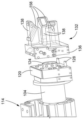
Referring now to FIG. 1, one exemplary embodiment of an alignment system 100 for a robotic assembly 102 is schematically illustrated. As shown, the robotic assembly 102 may include a robotic arm 104 that may rotate, pivot, or otherwise move about one or more axes 108 thereof relative to a base 106. The robotic assembly 102 may also move relative to one or more tool holders 110, each of which tool holders 110 may carry a plurality of different tools or end effectors 112 that may be attached to a working end 114 of the robotic arm 104. More specifically, the tool rack 110 may include one or more fixed posts 116, the fixed posts 116 configured to support and position each end effector 112 in a manner that facilitates the ability of the robotic arm 104 to autonomously reach and connect to the end effector 112 and replace a previously connected end effector 112. Further, each available end effector 112 may be designated for each post 116 of the tool rack 110 such that, once programmed or taught, the robotic arm 104 may autonomously retrieve or replace different end effectors 112 for different tasks.
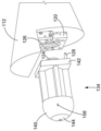
Turning to fig. 2, another exemplary embodiment of an alignment system 100 for a robotic assembly 102 is provided in greater detail. In the illustrated robotic assembly 102, the working end 116 of the robotic arm 104 may be configured to be mateably coupled to one or more interchangeable tools or end effectors 112 designed for different applications. For example, the robotic arm 104 may be coupled to a suitable end effector 112 and programmed with one or more algorithms to perform specific tasks (such as tasks related to measurement, manufacturing, positioning, assembly, installation, and so forth). As shown, the alignment system 100 may also be provided with an alignment device 118, which alignment device 118 may be temporarily attached between the robotic arm 104 and the end effector 112, for example, during the alignment process, and used to properly align the robotic arm 104 with the end effector 112. Once properly aligned, the alignment device 118 may be removed and the robotic arm 104 may be taught or programmed to an aligned position that is offset by a predetermined dimension of the alignment device 118.
As further shown in fig. 3 and 4, the alignment device 118 of fig. 2 may be disposed between a machine-side connector 120 and a tool-side connector 122. A machine side connector 120 may be disposed at a distal end of the robotic arm 104 and configured to mateably couple to a counterpart tool side connector 122 disposed at a proximal end of the end effector 112. As shown in fig. 3 and 4, for example, the machine-side connector 120 may include a male cylindrical key 124, the male cylindrical key 124 being sized and configured to be received within a female receptacle 126 of the tool-side connector 122. The machine-side connector 120 may also include one or more alignment pins 128, the alignment pins 128 designed to be received within corresponding alignment holes 130 of the tool-side connector 122. Further, the connectors 120, 122 may be designed with universal or commercial equipment such that any of a number of different end effectors 112 having compatible tool-side connectors 122 may be used on a given robotic arm 104. In other alternatives, the connectors 120, 122 may be customized for a particular application rather than commercial use. The tool-side connector 122 may also be removably locked to the machine-side connector 120 using mechanical, pneumatic, electrical, and/or magnetic locking means.
The alignment device 118 of fig. 2 may include a receiver 132 configured to couple to the machine-side connector 120 and a ball-shaped tool 134 configured to couple to the tool-side connector 122. As shown, the receptacle 132 of fig. 3 may include a proximal base portion 136 and a plurality of arms 138 extending distally therefrom, while the ball-shaped tool 134 of fig. 4 may include a ball-shaped end portion 140 and a distal base portion 142 coupled thereto. The proximal base portion 136 may be designed to mimic the tool-side connector 122 of the end effector 112 and engage with the machine-side connector 120. For example, the proximal base portion 136 may include a female receptacle 126 and an alignment hole 130, the female receptacle 126 and the alignment hole 130 configured to matingly receive a corresponding male cylindrical key 124 and alignment pin 128 of the machine-side connector 120. Similarly, the distal bottom portion 142 of the spherical tool 134 may be designed to mimic the machine-side connector 120 of the robotic arm 104 and engage with the tool-side connector 122. Correspondingly, the distal base portion 142 may include a male cylindrical key 124 and an alignment pin 128, the male cylindrical key 124 and the alignment pin 128 configured to be matingly received within the female receptacle 126 and the alignment hole 130 of the tool-side connector 122.
Turning now to fig. 5-7, one exemplary embodiment of the ball tool 134 is shown in greater detail. As shown, the ball tool 128 may include a locking post 144 coaxially disposed therethrough, extending between the ball end portion 140 and the distal base portion 142, and substantially flush with the ball end portion 140. Further, as shown in the cross-sectional views of fig. 6 and 7, the distal end of locking post 144 may include a threaded interface 146, with threaded interface 146 designed to engage a corresponding threaded inner surface 148 of distal base portion 142. The locking post 144 may also include a tapered tip 150, the tapered tip 150 being designed to mechanically engage with one or more locking pins 152 radially disposed about the cylindrical key 124 of the distal base portion 142. The locking post 144 is axially movable relative to the ball tool 134 to selectively engage the locking pin 152 between the locked and unlocked positions. More particularly, in the locked position, the locking pin 152 may extend radially from the cylindrical key 124 to engage the inner wall of the container 126, while in the unlocked position, the locking pin 152 may be retracted radially within the cylindrical key 124 to disengage the cylindrical key 124 from the tool-side connector 122.
In the embodiment shown in fig. 5-7, the distal base portion 142 may be locked within the receptacle 126 of the tool-side connector 122 by axially extending and/or rotating the locking post 144 relative to the ball-shaped tool 134 until the tapered tip 150 abuts and radially extends outward the locking pin 152. As shown in more detail in fig. 7, each locking pin 152 may provide a stepped interface 154 that retains the locking pin 152 within the cylindrical key 124. Conversely, to unlock the distal base portion 142 from the receptacle 126, the locking post 144 may be axially retracted and/or rotated relative to the ball tool 134 until the tapered tip 150 no longer contacts the locking pin 152, or at least until the locking pin 152 is sufficiently retracted to release the cylindrical key 124 from the receptacle 126. Although not shown, a coil spring, leaf spring, or other biasing mechanism commonly used in the art may be used to further bias locking pin 152 toward the center of cylindrical key 124 and into a fully retracted position. Further, axial and/or rotational actuation of the locking post 144 may be manually engaged or selectively engaged using mechanical, pneumatic, electrical, and/or magnetic actuation means.
Referring back to fig. 3 and 4, the arms 138 of the receiver 132 may be configured to engage with a spherical end portion 140 of the spherical tool 134. For example, the spherical end portion 140 of the spherical tool 134 may provide a spherical outer surface defined about the common tool center point 156. Correspondingly, the end of the arm 138 may have an inwardly contoured surface 158, the inwardly contoured surface 158 being sized and shaped to generally receive and uniformly contact the spherical outer surface of the spherical end portion 140 when properly positioned. Further, the contoured surface 158 may be configured to receive the outer surface of the spherical end portion 140 in such a manner that the receiver 132 is able to rotate and/or pivot about the spherical end portion 140 and its tool center point 156 while maintaining substantially uniform contact therewith. While the interface between the receiver 132 and the spherical tool 134 shown in fig. 3 and 4 is spherical, it should be understood that other interface types, such as cylindrical, elliptical, etc., may be similarly implemented to provide comparable results.
Turning to fig. 8, one exemplary embodiment of the receiver 132 is provided in greater detail. In the illustrated embodiment, the receiver 132 may include a plurality of arms 138 (such as three arms 138) extending distally from the proximal base portion 136, each arm 138 having a contoured surface 158 for receiving the spherical end portion 140 of the spherical tool 134. Additionally, the end of each arm 138 may include one or more indicators 160, the indicators 160 configured to track, monitor, or otherwise provide feedback regarding alignment (such as center point alignment and robotic arm alignment) between the robotic arm 104 and the end effector 112. With respect to center point alignment or alignment by linear robotic movement to align the center point of the receiver arm 138 with the tool center point 156 of the spherical tool 134, an indicator 160 may be used to indicate whether the spherical end portion 140 is sufficiently and uniformly received within the contoured surface 158 of all of the receiver arms 138. In terms of arm alignment while maintaining centerline point alignment or alignment via rotational robotic movement to align the receiver arm 138 about the rotational pose of the tool center point 156 of the spherical tool 134, an indicator 160 may be used to indicate whether to align the angular or rotational position, or spatial pose, of the receiver 132 relative to the tool center point 156 of the spherical tool 134, as desired. In fig. 8, for example, the center point alignment may be tracked by the indicator 160, while the arm alignment may be tracked based on a comparison between the edge of one or more of the arms 138 and any reference point that may be disposed on the outer surface of the spherical end portion 140.
As shown in fig. 8, each indicator 160 may include a mechanical rocker 162, the mechanical rocker 162 interacting with the contoured surface 158 and being pivotally displaceable within the receiver arm 138 about a rocker axis 164 between a raised position and a deflected position. The displacement of the rocker 162 may depend on the interaction with the spherical end portion 140 and correspond to the degree of linear motion required by the robotic assembly 102 to achieve center point alignment between the robotic arm 104 and the end effector 112. Each rocker 162 may also include a biasing mechanism 166, the biasing mechanism 166 biasing the rocker 162 into the raised position and deflecting the rocker 162 when the rocker 162 is disposed in contact with the spherical end portion 140. In addition, each indicator 160 can include at least one alignment mark 168, the alignment mark 168 moving with the rocker 162 and providing feedback regarding the alignment between the arm 104 and the end effector 112. For example, the markings 168 may be configured such that the markings 168 are clearly visible and substantially flush with the outer surface of the receiver arm 138 when the rocker 162 is sufficiently pressed into the deflected position by the spherical end portion 140. Conversely, the markings 168 may not be clearly visible or may be skewed relative to the arm 138 if the rocker 162 is not sufficiently depressed into the deflected position.
Referring to fig. 9-13, a variation of the indicator 160 of fig. 8 is provided that may be implemented in the receiver arm 138 of the receiver 132. For example, the indicator 160 in fig. 9 and 10 may provide a second proximal alignment marker 170 in addition to the first distal alignment marker 168 so that alignment may be tracked even when the field of view of the distal alignment marker 168 is obstructed. Similar to the distal alignment mark 168, the proximal alignment mark 170 may also be coupled to the rocker 162 and directly movable therewith. The proximal alignment marker 170 may also be configured to be substantially flush with the outer surface of the receiver arm 138 when the rocker 162 is sufficiently pressed into the deflected position by the spherical end portion 140, yet raised or extended relative to the arm 138. Specifically, if the rocker 162 is not sufficiently depressed into the deflected position, the indicia 170 may extend and skew relative to the arm 138. As further shown in fig. 10, the indicator 160 may also include a scale 172, the scale 172 being usable as a reference for determining the relative displacement of the distal alignment marker 168 and thus the degree of alignment or misalignment of the center point between the receiver arm 138 and the spherical end portion 140.
The embodiment of fig. 11 and 12 shows a further variant of the indicator 160 of fig. 8 to 10. In contrast to the rocker 162 of fig. 8-10, the rocker 162 in fig. 11 and 12 is pivotally displaceable about a rocker axis 164, the rocker axis 164 being disposed distally relative to the contoured surface 158. The overall mechanism of the indicator 160 in fig. 11 and 12 may remain the same, with the rocker 162 interacting with the contoured surface 158 and being displaceable between a raised position and a deflected position based on interaction with the spherical end portion 140. In addition, the indicator 160 of fig. 11 and 12 may be provided with one proximal alignment marker 170 and omit the distal alignment marker 168 of fig. 8-10. Additionally, and in contrast to the proximal alignment mark 170 of fig. 9 and 10, the movement of the proximal alignment mark 170 in fig. 11 and 12 may be limited to the outer surface of the receiver arm 138. For example, the proximal alignment marker 170 may be configured to be substantially flush with the outer surface of the receiver arm 138 when the rocker 162 is sufficiently pressed into the deflected position by the spherical end portion 140, yet be hidden or jammed within the arm 138. Additionally, the indicator 160 may also include a scale 172, the scale 172 being disposed relative to the proximal alignment mark 170 and used as a reference for determining the degree of alignment or misalignment.
In addition, the embodiment of fig. 13 shows another modification of the indicator 160 of fig. 8 to 12. Similar to the indicator 160 shown in fig. 8, the rocker 162 in fig. 13 may be configured to pivotally displace about a rocker axis 164 adjacently disposed relative to the contoured surface 158. Additionally, similar to fig. 8, the indicator 160 of fig. 13 may be provided with distal alignment marks 168, the distal alignment marks 168 being visible from the outer surface of the receiver arm 138. However, in contrast to the previous embodiments, the indicator 160 of fig. 13 may further include one or more sensing devices 174, the sensing devices 174 configured to detect displacement of the rocker 162 and generate one or more outputs indicative of the corresponding alignment and/or offset distances associated with the end effector 112. As shown in fig. 13, for example, the sensing device 174 may employ a pressure sensor or linear encoder coupled to the rocker 162 and/or the biasing mechanism 166. Other types of sensing devices 174 and other arrangements for sensing displacement and/or alignment may also be used. Further, the output produced by sensing device 174 may be provided mechanically, electrically, pneumatically, magnetically, or a combination of these ways as an output signal or any other form of information that is indicative of the alignment between receiver 132 and ball tool 134.
Turning now to FIG. 14, one exemplary method 176 of aligning the robotic arm 104 with the end effector 112 is schematically illustrated. As shown, the method 176 may initially couple the receptacle 132 to the robotic arm 104 in block 176-1. With additional reference to fig. 3, for example, the female receptacle 126 and the alignment hole 130 of the proximal bottom portion 136 of the receiver 132 may be aligned fixed to the male cylindrical key 124 and the alignment pin 128 of the machine-side connector 120. Similarly, the method 176 may couple the ball tool 134 to the end effector 112 in block 176-2. As shown in fig. 4, for example, the female receptacle 126 and the alignment hole 130 of the tool-side connector 122 of the end effector 112 may align the male cylindrical key 124 and the alignment pin 128 secured to the distal base portion 142 of the spherical tool 134. Once each receiver 132 is coupled to the robotic arm 104 and the spherical tool 134 is coupled to the end effector 112, the spatial pose of the robotic arm 104 may be adjusted relative to the tool center point 156 of the spherical tool 134 to begin the alignment process.
As shown in fig. 14, the method 176 may adjust the linear position of the robotic arm 104, or the linear component of its spatial pose, relative to the spherical tool 134 in block 176-3 until at least center point alignment is achieved, or until at least the tool center point 156 of the spherical tool 134 coincides with the center point of the receiver arm 138. Further, in certain embodiments, the center point alignment may be used to equally position the receiver arm 138 about the tool center point 156 of the spherical end portion 140 regardless of the relative rotational positions of the robotic arm 104 and the end effector 112. As shown in fig. 15, the linear position of the robotic arm 104 may be adjusted relative to the end effector 112 until the spherical end portion 140 is sufficiently received in each arm 138 of the receiver 132. The method 176 may determine whether center point alignment has been achieved based on feedback provided by the indicator 160 of the receiver 132 in block 176-4. A particular point alignment is achieved if, for example, all of the indicators 160 indicate that the spherical end portion 140 is sufficiently received within the receiver arm 138. However, if any of the indicators 160 indicate misalignment, the position of the robotic arm 104 may be readjusted in block 176-3, for example, in the direction recommended by the misalignment indicator 160 until proper center point alignment is achieved.
The method 176 may also adjust the spatial pose of the robotic arm 104 relative to the end effector 112 in block 176-5 until the desired arm alignment is achieved, or until its rotational position is aligned or set to a desired position. If center point alignment has been achieved, the robotic arm 104 may be adjusted using only rotational movement, such as about the tool center point 156, so that the center point alignment is not disturbed. As shown in fig. 16, for example, the robotic arm 104 may rotate about its axis 178 and/or pivot relative to the tool center point 156 of the spherical end portion 140 to achieve a desired arm alignment with the end effector 112. However, in other embodiments, the desired arm alignment may be achieved independently of the center point alignment, employing a combination of rotational and linear robotic movement. In either case, the method 176 may determine whether the desired arm alignment has been achieved in block 176-6, for example, based on feedback provided by the indicators 160 of the arms 138 of the receivers 132 capable of tracking arm alignment and/or based on a position relative to a reference point disposed on the outer surface of the spherical end portion 140. If, for example, all of the indicators 160 and/or receiver arms 138 indicate that the robotic arm 104 is axially and pivotally positioned as desired relative to the end effector 112, a desired arm alignment is created. If either of the indicator 160 or the arm 138 indicates a misalignment, the rotational position of the robotic arm 104 may be readjusted in block 176-5.
If the spatial pose of the robotic arm 104 (in terms of both linear and rotational components) is sufficiently aligned with the end effector 112, the method 176 may program the pose of the robotic arm 104, or recoverably store it in memory, for reference in relation to future automated operations of a given end effector 112 or other compatible tool, in block 176-7. Further, when programming the pose of the robotic arm 104, the actual pose of the robotic arm 104 may be adjusted to correct for the size or length of the alignment device 118 that is installed only during the course of alignment and that is not otherwise used. As shown in fig. 17, the alignment pose of the robotic arm 104 may be finalized by biasing the actual pose by a predetermined length of the alignment device 118 and any other predetermined dimension of the alignment device 118 relative to the tool center point 156, for example. Once the alignment pose is finally calculated or determined, the appropriate commands for invoking the alignment pose may be programmed or stored in memory for later reference. In other embodiments, the robotic arm 104 may also be capable of autonomously positioning different end effectors 112 within a given tool rack 110, and autonomously learning the different spatial poses necessary to reach the end effectors 112.
It should be understood that the above description provides examples of the disclosed apparatus, system, and method. However, it is contemplated that other implementations of the present disclosure differ in detail from the above examples. All references to the disclosure or examples thereof are intended to reference the particular example being discussed at this time and are not intended to imply any limitation as to the scope of the disclosure more generally. All other specific language and non-compliance with respect to a particular feature is intended to indicate a lack of preference for that feature, but does not exclude it from the scope of the disclosure entirely unless otherwise indicated. All methods described herein can be performed in any suitable order unless otherwise indicated herein or otherwise clearly contradicted by context.
Additionally, the present disclosure includes embodiments according to the following clauses:
clause 1. a device for aligning a robotic arm with an end effector, the device comprising:
a ball tool having a ball end portion and a distal base portion configured to be detachably coupled to the end effector; and
a receiver having a plurality of arms and a proximal base portion configured to be detachably coupled to the robotic arm;
wherein the arm is configured to receive the spherical end portion and includes one or more indicators configured to track alignment between the robotic arm and the end effector.
The device of clause 2. the device of clause 1, wherein the distal base portion comprises a plurality of locking pins configured to engage with the end effector, and the proximal base portion comprises a connector configured to receive the plurality of locking pins of the robotic arm.
The device of clause 3. the device of clause 2, wherein the ball-shaped tool further comprises a locking post coaxially disposed therethrough, the locking post axially movable relative to the ball-shaped tool and configured to selectively engage the locking pin of the distal base portion to a locked position.
The device of any of clauses 1-3, wherein the distal base portion is configured to be detachably coupled to a tool-side connecting base of the end effector and the proximal base portion is configured to be detachably coupled to a machine-side connecting base of the robotic arm.
Clause 5. the apparatus of any one of clauses 1-4, wherein the arm of the receiver includes a shaped end configured to matingly receive the spherical end portion of the spherical tool and rotate about a tool center point of the spherical tool.
The device of clause 6. the device of clause 5, wherein the spherical end portion engages the shaped end of the receiver to thereby couple the receiver and the robotic arm to the spherical tool and the end effector.
The device of any of clauses 1-6, wherein the arm and the indicator are configured to indicate a center point alignment and an arm alignment between the robotic arm and the end effector.
The device of clause 8, the device of clause 1, wherein the indicator is pivotally displaceable relative to the arm based on interaction with the spherical end portion, the displacement of the indicator corresponding to at least a center point alignment between the robotic arm and the end effector.
The device of clause 9, the device of clause 8, wherein the indicator further comprises one or more sensing devices configured to detect the displacement and generate one or more outputs indicative of the corresponding alignment and offset distance associated with the end effector.
Clause 10. a system for programming the alignment of a robotic assembly comprising the apparatus of clause 1, the system further comprising:
an end effector having a tool-side connection base;
a robotic arm having a machine side connection base movable to one of a plurality of programmable poses relative to the end effector;
wherein the ball-shaped tool having a ball-shaped end portion and a distal bottom portion is configured to be detachably coupled to the tool-side connection bottom; and
wherein the receiver having a plurality of arms and a proximal base portion is configured to be detachably coupled to the machine side connecting base;
wherein the arm is configured to matingly receive the spherical end portion and includes one or more indicators configured to indicate alignment between the robotic arm and the end effector.
The system of clause 11. the system of clause 10, wherein the distal base portion comprises a plurality of locking pins and alignment pins configured to engage with the end effector, and the proximal base portion comprises a connector configured to receive the plurality of locking pins and alignment pins of the robotic arm.
Clause 12. the system of clause 11, wherein the ball-shaped tool further comprises a locking post coaxially disposed therethrough, the locking post axially movable relative to the ball-shaped tool and configured to selectively engage the locking pin of the distal base portion to a locked position.
Clause 13. the system of clause 11, wherein each of the distal and proximal sole portions is provided with one of a pneumatic locking mechanism and a mechanical locking mechanism.
Clause 14. the system of clause 10, wherein the arm of the receiver comprises a shaped end configured to matingly receive the spherical end portion of the spherical tool and rotate about a tool center point of the spherical tool.
Clause 15. the system of clause 10, wherein the indicator is movable relative to the arm based on interaction with the spherical end portion, the displacement of the indicator corresponding to at least a center point alignment between the robotic arm and the end effector.
Clause 16. the system of clause 15, wherein the robotic arm can be manually adjusted until the indicator indicates proper alignment between the robotic arm and the end effector, and the pose of the robotic arm can be programmed when the indicator indicates proper alignment.
Clause 17. the system of clause 15, wherein the indicator further comprises one or more sensing devices configured to detect the displacement and generate one or more electrical signals indicative of the corresponding alignment.
Clause 18. a method of aligning a robotic arm with an end effector, the method comprising:
providing a ball-shaped tool having a ball-shaped end portion and a distal base portion detachably coupled to the end effector;
providing a receiver having a plurality of arms, a plurality of indicators, and a proximal base portion detachably coupled to the robotic arm;
adjusting the pose of the robotic arm relative to the end effector until the indicator indicates proper alignment; and
programming the pose of the robotic arm when the indicator indicates proper alignment.
Clause 19. the method of clause 18, wherein the proper alignment is indicated based on a linear component that is aligned when the spherical end portion is sufficiently received in each of the arms and a rotational component that is aligned when the arms are in a desired orientation relative to a tool center point of the spherical end portion.
Clause 20. the method of clause 18, wherein the indicator is pivotally displaceable relative to the arm based on interaction with the spherical end portion, the displacement of the indicator corresponding to at least a center point alignment between the robotic arm and the end effector.
Accordingly, this disclosure includes all modifications and equivalents of the subject matter recited in the claims appended hereto as permitted by applicable law. Moreover, any combination of the above-described elements in all possible variations thereof is encompassed by the disclosure unless otherwise indicated herein or otherwise clearly contradicted by context.
Claims (14)
1. An apparatus (118) for aligning a robotic arm (104) with an end effector (112), the apparatus comprising:
a ball-shaped tool (134), the ball-shaped tool (134) having a ball-shaped end portion (140) and a distal base portion (142) configured to be detachably coupled to the end effector (112); and
a receptacle (132), the receptacle (132) having a plurality of arms (138) and a proximal base portion (136) configured to be detachably coupled to the robotic arm (104);
wherein the arm (138) is configured to receive the spherical end portion (140) and includes one or more indicators (160), the indicators (160) configured to track alignment between the robotic arm (104) and the end effector (112).
2. The device (118) of claim 1, wherein the distal base portion (142) includes a plurality of locking pins (152) configured to engage with the end effector (112), and the proximal base portion (136) includes a connector configured to receive the plurality of locking pins (152) of the robotic arm (104),
wherein the ball tool (134) further comprises a locking post (144) disposed coaxially therethrough, the locking post (144) being axially movable relative to the ball tool (134) and configured to selectively engage the locking pin (152) of the distal base portion (142) to a locked position.
3. The device (118) of claim 1 or 2, wherein the distal base portion (142) is configured to be detachably coupled to a tool-side connection base (122) of the end effector (112), and the proximal base portion (136) is configured to be detachably coupled to a machine-side connection base (120) of the robotic arm (104).
4. The device (118) of claim 1, wherein the arm (138) of the receiver (132) includes a shaped end configured to matingly receive the ball end portion (140) of the ball tool (134) and rotate about a tool center point (156) of the ball tool (134).
5. The device (118) of claim 4, wherein the spherical end portion (140) engages the shaped end of the receiver (132) to couple the receiver (132) and the robotic arm (104) to the spherical tool (134) and the end effector (112).
6. The device (118) of claim 1, wherein the arm (138) and the indicator (160) are configured to indicate a center point alignment and an arm alignment between the robotic arm (104) and the end effector (112).
7. The device (118) of claim 1, wherein the indicator (160) is pivotally displaceable relative to the arm (138) based on interaction with the spherical end portion (140), the displacement of the indicator (160) corresponding to at least a center point alignment between the robotic arm (104) and the end effector (112).
8. The device (118) of claim 7, wherein the indicator (160) further comprises one or more sensing devices (174), the sensing devices (174) configured to detect the displacement and generate one or more outputs indicative of corresponding alignment and offset distances associated with the end effector (112).
9. A system (100) for programming the alignment of a robotic assembly (102) comprising the apparatus of claim 1, the system further comprising:
an end effector (112), the end effector (112) having a tool-side connection base (122);
a robotic arm (104), the robotic arm (104) having a machine-side connection base (120) movable to one of a plurality of programmable poses relative to the end effector (112);
wherein the spherical tool (134) having a spherical end portion (140) and a distal bottom portion (142) is configured to be detachably coupled to the tool-side connection bottom (122); and
wherein the receptacle (132) having a plurality of arms (138) and a proximal base portion (136) is configured to be detachably coupled to the machine side connection base (120);
wherein the arm (138) is configured to matingly receive the spherical end portion (140) and includes one or more indicators (160) configured to indicate alignment between the robotic arm (104) and the end effector (112).
10. The system (100) of claim 9, wherein the distal base portion (142) includes a plurality of locking pins (152) and alignment pins (128) configured to engage with the end effector (112), and the proximal base portion (136) includes a connector configured to receive the plurality of locking pins (152) and alignment pins (128) of the robotic arm (104).
11. The system (100) according to claim 10, wherein the ball-shaped tool (134) further includes a locking post (144) coaxially disposed therethrough, the locking post (144) axially movable relative to the ball-shaped tool (134) and configured to selectively engage the locking pin (152) of the distal base portion (142) to a locked position.
12. The system (100) of claim 9, wherein the indicator (160) is displaceable relative to the arm (138) based on interaction with the spherical end portion (140), the displacement of the indicator (160) corresponding to at least a center point alignment between the robotic arm (104) and the end effector (112), wherein the robotic arm (104) is manually adjustable until the indicator (160) indicates proper alignment between the robotic arm (104) and the end effector (112), and the pose of the robotic arm (104) is programmable when the indicator (160) indicates proper alignment.
13. The system (100) according to claim 12, wherein the indicator (160) further includes one or more sensing devices (174) configured to detect the displacement and generate one or more electrical signals indicative of the corresponding alignment.
14. A method (176) of aligning a robotic arm (104) with an end effector (112), the method comprising:
providing a ball-shaped tool (134) having a ball-shaped end portion (140) and a distal base portion (142) detachably coupled to the end effector (112);
providing a receptacle (132), the receptacle (132) having a plurality of arms (138), a plurality of indicators (160), and a proximal base portion (136) detachably coupled to the robotic arm (104);
adjusting the pose of the robotic arm (104) relative to the end effector (112) until the indicator (160) indicates proper alignment; and
programming the pose of the robotic arm (104) when the indicator (160) indicates proper alignment;
wherein proper alignment is indicated based on a linear component that aligns when the spherical end portion (140) is sufficiently received in each of the arms (138) and a rotational component that aligns when the arms (138) are in a desired orientation relative to a tool center point (156) of the spherical end portion (140).
Applications Claiming Priority (2)
| Application Number | Priority Date | Filing Date | Title |
|---|---|---|---|
| US14/856,187 | 2015-09-16 | ||
| US14/856,187 US10035269B2 (en) | 2015-09-16 | 2015-09-16 | Enhanced robotic teaching tool |
Publications (2)
| Publication Number | Publication Date |
|---|---|
| CN106541397A CN106541397A (en) | 2017-03-29 |
| CN106541397B true CN106541397B (en) | 2021-07-27 |
Family
ID=56985734
Family Applications (1)
| Application Number | Title | Priority Date | Filing Date |
|---|---|---|---|
| CN201610525664.9A Active CN106541397B (en) | 2015-09-16 | 2016-07-06 | Enhanced robotic teaching tool |
Country Status (4)
| Country | Link |
|---|---|
| US (1) | US10035269B2 (en) |
| JP (1) | JP6879697B2 (en) |
| CN (1) | CN106541397B (en) |
| GB (1) | GB2543140B (en) |
Families Citing this family (8)
| Publication number | Priority date | Publication date | Assignee | Title |
|---|---|---|---|---|
| AT517928A2 (en) * | 2015-11-06 | 2017-05-15 | Keba Ag | Control system for electrically controlled systems |
| US11528913B1 (en) * | 2018-02-13 | 2022-12-20 | Kent Deemter | Automated food preparation apparatus |
| KR102148251B1 (en) * | 2018-11-23 | 2020-08-26 | 한국기계연구원 | Removable teaching device |
| US11402353B2 (en) * | 2019-01-21 | 2022-08-02 | The Boeing Company | Imaging beam adjustments on a non-destructive inspection sensor situated on a robotic effector to accommodate in situ conditions |
| WO2020257565A1 (en) * | 2019-06-20 | 2020-12-24 | Bono Peter L | Robotically positioned x-ray and c-arm |
| IT201900020844A1 (en) * | 2019-11-12 | 2021-05-12 | Lucchese Ind S R L | ISLAND ROBOTIC APPARATUS FOR THE ASSEMBLY OF FINISHED PRODUCTS AND RELATED ASSEMBLY METHOD |
| CN112873257B (en) * | 2021-01-13 | 2022-07-12 | 刘湘洪 | Industrial robot's tip work piece quick replacement device |
| CN112959309B (en) * | 2021-04-01 | 2022-04-05 | 杭州键嘉机器人有限公司 | Tool for searching mechanical arm working point and registering mechanical arm |
Citations (4)
| Publication number | Priority date | Publication date | Assignee | Title |
|---|---|---|---|---|
| EP2383079A2 (en) * | 2010-04-28 | 2011-11-02 | Kabushiki Kaisha Yaskawa Denki | System and method for judging success or failure of work of robot |
| JP2012112894A (en) * | 2010-11-26 | 2012-06-14 | Tohoku Univ | Method for centering probe |
| CN103115629A (en) * | 2013-01-23 | 2013-05-22 | 天津大学 | Method for rapidly restoring tool coordinate frame in flexible vision measurement system for robots |
| CN103365246A (en) * | 2012-04-05 | 2013-10-23 | 菲迪亚股份公司 | Device for error correction for CNC machines |
Family Cites Families (11)
| Publication number | Priority date | Publication date | Assignee | Title |
|---|---|---|---|---|
| US5155423A (en) * | 1986-02-18 | 1992-10-13 | Robotics Research Corporation | Industrial robot with servo |
| US6057695A (en) * | 1993-09-15 | 2000-05-02 | Intest Corporation | Method and apparatus for automated docking of a test head to a device handler |
| JP3421608B2 (en) * | 1999-04-08 | 2003-06-30 | ファナック株式会社 | Teaching model generator |
| WO2006022201A1 (en) * | 2004-08-25 | 2006-03-02 | Kabushiki Kaisha Yaskawa Denki | Robot evaluation system and evaluation method |
| US7444205B2 (en) * | 2004-10-29 | 2008-10-28 | Neil Desmond | Modular self structuring and computing system |
| IT1399603B1 (en) * | 2010-04-26 | 2013-04-26 | Scuola Superiore Di Studi Universitari E Di Perfez | ROBOTIC SYSTEM FOR MINIMUM INVASIVE SURGERY INTERVENTIONS |
| JP5130509B2 (en) | 2010-08-11 | 2013-01-30 | 川田工業株式会社 | End effector exchange device for work robot and work robot having part thereof |
| US8961537B2 (en) * | 2011-08-24 | 2015-02-24 | The Chinese University Of Hong Kong | Surgical robot with hybrid passive/active control |
| US9004201B2 (en) * | 2012-04-18 | 2015-04-14 | Board Of Trustees Of Michigan State University | Jumping robot |
| CN103707025B (en) * | 2012-09-29 | 2016-06-08 | 鸿富锦精密工业(深圳)有限公司 | Disassembling system |
| DE102014226933B3 (en) * | 2014-12-23 | 2016-03-24 | Kuka Roboter Gmbh | Device and method for recording positions |
-
2015
- 2015-09-16 US US14/856,187 patent/US10035269B2/en active Active
-
2016
- 2016-07-06 CN CN201610525664.9A patent/CN106541397B/en active Active
- 2016-08-17 GB GB1614071.7A patent/GB2543140B/en active Active
- 2016-09-02 JP JP2016171831A patent/JP6879697B2/en active Active
Patent Citations (4)
| Publication number | Priority date | Publication date | Assignee | Title |
|---|---|---|---|---|
| EP2383079A2 (en) * | 2010-04-28 | 2011-11-02 | Kabushiki Kaisha Yaskawa Denki | System and method for judging success or failure of work of robot |
| JP2012112894A (en) * | 2010-11-26 | 2012-06-14 | Tohoku Univ | Method for centering probe |
| CN103365246A (en) * | 2012-04-05 | 2013-10-23 | 菲迪亚股份公司 | Device for error correction for CNC machines |
| CN103115629A (en) * | 2013-01-23 | 2013-05-22 | 天津大学 | Method for rapidly restoring tool coordinate frame in flexible vision measurement system for robots |
Also Published As
| Publication number | Publication date |
|---|---|
| CN106541397A (en) | 2017-03-29 |
| GB2543140B (en) | 2019-12-11 |
| US20170072567A1 (en) | 2017-03-16 |
| JP2017056548A (en) | 2017-03-23 |
| US10035269B2 (en) | 2018-07-31 |
| JP6879697B2 (en) | 2021-06-02 |
| GB201614071D0 (en) | 2016-09-28 |
| GB2543140A (en) | 2017-04-12 |
Similar Documents
| Publication | Publication Date | Title |
|---|---|---|
| CN106541397B (en) | Enhanced robotic teaching tool | |
| RU2746931C2 (en) | Method and device for a pliable working body | |
| EP3256811B1 (en) | Laser gauge for robotic calibration and monitoring | |
| CN111015733B (en) | Attachment mechanism, robot device, and attachment method | |
| US6317699B1 (en) | Device and method for calibrating a robot | |
| US10773313B2 (en) | Turret tool rest and machine tool | |
| EP2298508B1 (en) | Measurement of a manipulator | |
| KR102091917B1 (en) | Gear mechanism assembly and assembly method | |
| CN109641350B (en) | Plug-in adapter, adjusting device and associated robot | |
| JP2004508954A (en) | Positioning device and system | |
| CN105643369A (en) | Cooperation system having machine tool and robot | |
| US10065319B2 (en) | Tool calibration apparatus of robot manipulator | |
| JP2019504776A (en) | Robot effector unit, working device having a robot, and method for exchanging a robot effector | |
| JP2017056548A5 (en) | ||
| JP2006297559A (en) | Calibration system and robot's calibration method | |
| JP7343349B2 (en) | How to determine the position of the robot, measurement jig, and tool tip | |
| JP5179760B2 (en) | Coordinate measuring aid, coordinate measuring probe and coordinate measuring machine | |
| DE10002230A1 (en) | Adaptive robot guidance method, uses successive measurements with master piece and actual component for determining offset vectors used for adaption of robot movement program | |
| TWI808398B (en) | Method of calibrating a co-ordinate positioning machine | |
| US20160096245A1 (en) | Orthogonal Positioning Instrument, System, And Method For Automatic Machines | |
| WO2021047777A1 (en) | Measurement device for monitoring robot-guided processing of a work piece surface and related method | |
| DE10203002B4 (en) | Device for calibrating a robot | |
| US20200016772A1 (en) | Hand connection position variable device and robot | |
| EP3603904B1 (en) | Robot system | |
| JP2005028529A (en) | Device for positioning industrial robot into its original position |
Legal Events
| Date | Code | Title | Description |
|---|---|---|---|
| PB01 | Publication | ||
| PB01 | Publication | ||
| SE01 | Entry into force of request for substantive examination | ||
| SE01 | Entry into force of request for substantive examination | ||
| GR01 | Patent grant | ||
| GR01 | Patent grant |