CN106536955B - Tripod type constant velocity universal joint and method for manufacturing the same - Google Patents
Tripod type constant velocity universal joint and method for manufacturing the same Download PDFInfo
- Publication number
- CN106536955B CN106536955B CN201580038588.2A CN201580038588A CN106536955B CN 106536955 B CN106536955 B CN 106536955B CN 201580038588 A CN201580038588 A CN 201580038588A CN 106536955 B CN106536955 B CN 106536955B
- Authority
- CN
- China
- Prior art keywords
- roller
- tripod
- constant velocity
- universal joint
- velocity universal
- Prior art date
- Legal status (The legal status is an assumption and is not a legal conclusion. Google has not performed a legal analysis and makes no representation as to the accuracy of the status listed.)
- Active
Links
Images


Classifications
-
- F—MECHANICAL ENGINEERING; LIGHTING; HEATING; WEAPONS; BLASTING
- F16—ENGINEERING ELEMENTS AND UNITS; GENERAL MEASURES FOR PRODUCING AND MAINTAINING EFFECTIVE FUNCTIONING OF MACHINES OR INSTALLATIONS; THERMAL INSULATION IN GENERAL
- F16C—SHAFTS; FLEXIBLE SHAFTS; ELEMENTS OR CRANKSHAFT MECHANISMS; ROTARY BODIES OTHER THAN GEARING ELEMENTS; BEARINGS
- F16C33/00—Parts of bearings; Special methods for making bearings or parts thereof
- F16C33/30—Parts of ball or roller bearings
- F16C33/58—Raceways; Race rings
- F16C33/64—Special methods of manufacture
-
- C—CHEMISTRY; METALLURGY
- C21—METALLURGY OF IRON
- C21D—MODIFYING THE PHYSICAL STRUCTURE OF FERROUS METALS; GENERAL DEVICES FOR HEAT TREATMENT OF FERROUS OR NON-FERROUS METALS OR ALLOYS; MAKING METAL MALLEABLE, e.g. BY DECARBURISATION OR TEMPERING
- C21D6/00—Heat treatment of ferrous alloys
-
- C—CHEMISTRY; METALLURGY
- C21—METALLURGY OF IRON
- C21D—MODIFYING THE PHYSICAL STRUCTURE OF FERROUS METALS; GENERAL DEVICES FOR HEAT TREATMENT OF FERROUS OR NON-FERROUS METALS OR ALLOYS; MAKING METAL MALLEABLE, e.g. BY DECARBURISATION OR TEMPERING
- C21D9/00—Heat treatment, e.g. annealing, hardening, quenching or tempering, adapted for particular articles; Furnaces therefor
- C21D9/38—Heat treatment, e.g. annealing, hardening, quenching or tempering, adapted for particular articles; Furnaces therefor for roll bodies
-
- C—CHEMISTRY; METALLURGY
- C21—METALLURGY OF IRON
- C21D—MODIFYING THE PHYSICAL STRUCTURE OF FERROUS METALS; GENERAL DEVICES FOR HEAT TREATMENT OF FERROUS OR NON-FERROUS METALS OR ALLOYS; MAKING METAL MALLEABLE, e.g. BY DECARBURISATION OR TEMPERING
- C21D9/00—Heat treatment, e.g. annealing, hardening, quenching or tempering, adapted for particular articles; Furnaces therefor
- C21D9/40—Heat treatment, e.g. annealing, hardening, quenching or tempering, adapted for particular articles; Furnaces therefor for rings; for bearing races
-
- F—MECHANICAL ENGINEERING; LIGHTING; HEATING; WEAPONS; BLASTING
- F16—ENGINEERING ELEMENTS AND UNITS; GENERAL MEASURES FOR PRODUCING AND MAINTAINING EFFECTIVE FUNCTIONING OF MACHINES OR INSTALLATIONS; THERMAL INSULATION IN GENERAL
- F16C—SHAFTS; FLEXIBLE SHAFTS; ELEMENTS OR CRANKSHAFT MECHANISMS; ROTARY BODIES OTHER THAN GEARING ELEMENTS; BEARINGS
- F16C13/00—Rolls, drums, discs, or the like; Bearings or mountings therefor
- F16C13/006—Guiding rollers, wheels or the like, formed by or on the outer element of a single bearing or bearing unit, e.g. two adjacent bearings, whose ratio of length to diameter is generally less than one
-
- F—MECHANICAL ENGINEERING; LIGHTING; HEATING; WEAPONS; BLASTING
- F16—ENGINEERING ELEMENTS AND UNITS; GENERAL MEASURES FOR PRODUCING AND MAINTAINING EFFECTIVE FUNCTIONING OF MACHINES OR INSTALLATIONS; THERMAL INSULATION IN GENERAL
- F16D—COUPLINGS FOR TRANSMITTING ROTATION; CLUTCHES; BRAKES
- F16D3/00—Yielding couplings, i.e. with means permitting movement between the connected parts during the drive
- F16D3/16—Universal joints in which flexibility is produced by means of pivots or sliding or rolling connecting parts
- F16D3/20—Universal joints in which flexibility is produced by means of pivots or sliding or rolling connecting parts one coupling part entering a sleeve of the other coupling part and connected thereto by sliding or rolling members
- F16D3/202—Universal joints in which flexibility is produced by means of pivots or sliding or rolling connecting parts one coupling part entering a sleeve of the other coupling part and connected thereto by sliding or rolling members one coupling part having radially projecting pins, e.g. tripod joints
- F16D3/205—Universal joints in which flexibility is produced by means of pivots or sliding or rolling connecting parts one coupling part entering a sleeve of the other coupling part and connected thereto by sliding or rolling members one coupling part having radially projecting pins, e.g. tripod joints the pins extending radially outwardly from the coupling part
- F16D3/2055—Universal joints in which flexibility is produced by means of pivots or sliding or rolling connecting parts one coupling part entering a sleeve of the other coupling part and connected thereto by sliding or rolling members one coupling part having radially projecting pins, e.g. tripod joints the pins extending radially outwardly from the coupling part having three pins, i.e. true tripod joints
-
- F—MECHANICAL ENGINEERING; LIGHTING; HEATING; WEAPONS; BLASTING
- F16—ENGINEERING ELEMENTS AND UNITS; GENERAL MEASURES FOR PRODUCING AND MAINTAINING EFFECTIVE FUNCTIONING OF MACHINES OR INSTALLATIONS; THERMAL INSULATION IN GENERAL
- F16C—SHAFTS; FLEXIBLE SHAFTS; ELEMENTS OR CRANKSHAFT MECHANISMS; ROTARY BODIES OTHER THAN GEARING ELEMENTS; BEARINGS
- F16C19/00—Bearings with rolling contact, for exclusively rotary movement
- F16C19/22—Bearings with rolling contact, for exclusively rotary movement with bearing rollers essentially of the same size in one or more circular rows, e.g. needle bearings
- F16C19/44—Needle bearings
- F16C19/46—Needle bearings with one row or needles
- F16C19/466—Needle bearings with one row or needles comprising needle rollers and an outer ring, i.e. subunit without inner ring
-
- F—MECHANICAL ENGINEERING; LIGHTING; HEATING; WEAPONS; BLASTING
- F16—ENGINEERING ELEMENTS AND UNITS; GENERAL MEASURES FOR PRODUCING AND MAINTAINING EFFECTIVE FUNCTIONING OF MACHINES OR INSTALLATIONS; THERMAL INSULATION IN GENERAL
- F16C—SHAFTS; FLEXIBLE SHAFTS; ELEMENTS OR CRANKSHAFT MECHANISMS; ROTARY BODIES OTHER THAN GEARING ELEMENTS; BEARINGS
- F16C23/00—Bearings for exclusively rotary movement adjustable for aligning or positioning
- F16C23/06—Ball or roller bearings
- F16C23/08—Ball or roller bearings self-adjusting
-
- F—MECHANICAL ENGINEERING; LIGHTING; HEATING; WEAPONS; BLASTING
- F16—ENGINEERING ELEMENTS AND UNITS; GENERAL MEASURES FOR PRODUCING AND MAINTAINING EFFECTIVE FUNCTIONING OF MACHINES OR INSTALLATIONS; THERMAL INSULATION IN GENERAL
- F16C—SHAFTS; FLEXIBLE SHAFTS; ELEMENTS OR CRANKSHAFT MECHANISMS; ROTARY BODIES OTHER THAN GEARING ELEMENTS; BEARINGS
- F16C29/00—Bearings for parts moving only linearly
- F16C29/04—Ball or roller bearings
- F16C29/045—Ball or roller bearings having rolling elements journaled in one of the moving parts
-
- F—MECHANICAL ENGINEERING; LIGHTING; HEATING; WEAPONS; BLASTING
- F16—ENGINEERING ELEMENTS AND UNITS; GENERAL MEASURES FOR PRODUCING AND MAINTAINING EFFECTIVE FUNCTIONING OF MACHINES OR INSTALLATIONS; THERMAL INSULATION IN GENERAL
- F16D—COUPLINGS FOR TRANSMITTING ROTATION; CLUTCHES; BRAKES
- F16D3/00—Yielding couplings, i.e. with means permitting movement between the connected parts during the drive
- F16D3/16—Universal joints in which flexibility is produced by means of pivots or sliding or rolling connecting parts
- F16D3/20—Universal joints in which flexibility is produced by means of pivots or sliding or rolling connecting parts one coupling part entering a sleeve of the other coupling part and connected thereto by sliding or rolling members
- F16D3/202—Universal joints in which flexibility is produced by means of pivots or sliding or rolling connecting parts one coupling part entering a sleeve of the other coupling part and connected thereto by sliding or rolling members one coupling part having radially projecting pins, e.g. tripod joints
- F16D2003/2026—Universal joints in which flexibility is produced by means of pivots or sliding or rolling connecting parts one coupling part entering a sleeve of the other coupling part and connected thereto by sliding or rolling members one coupling part having radially projecting pins, e.g. tripod joints with trunnion rings, i.e. with tripod joints having rollers supported by a ring on the trunnion
-
- F—MECHANICAL ENGINEERING; LIGHTING; HEATING; WEAPONS; BLASTING
- F16—ENGINEERING ELEMENTS AND UNITS; GENERAL MEASURES FOR PRODUCING AND MAINTAINING EFFECTIVE FUNCTIONING OF MACHINES OR INSTALLATIONS; THERMAL INSULATION IN GENERAL
- F16D—COUPLINGS FOR TRANSMITTING ROTATION; CLUTCHES; BRAKES
- F16D2250/00—Manufacturing; Assembly
- F16D2250/0038—Surface treatment
- F16D2250/0053—Hardening
-
- F—MECHANICAL ENGINEERING; LIGHTING; HEATING; WEAPONS; BLASTING
- F16—ENGINEERING ELEMENTS AND UNITS; GENERAL MEASURES FOR PRODUCING AND MAINTAINING EFFECTIVE FUNCTIONING OF MACHINES OR INSTALLATIONS; THERMAL INSULATION IN GENERAL
- F16D—COUPLINGS FOR TRANSMITTING ROTATION; CLUTCHES; BRAKES
- F16D2300/00—Special features for couplings or clutches
- F16D2300/10—Surface characteristics; Details related to material surfaces
-
- Y—GENERAL TAGGING OF NEW TECHNOLOGICAL DEVELOPMENTS; GENERAL TAGGING OF CROSS-SECTIONAL TECHNOLOGIES SPANNING OVER SEVERAL SECTIONS OF THE IPC; TECHNICAL SUBJECTS COVERED BY FORMER USPC CROSS-REFERENCE ART COLLECTIONS [XRACs] AND DIGESTS
- Y10—TECHNICAL SUBJECTS COVERED BY FORMER USPC
- Y10S—TECHNICAL SUBJECTS COVERED BY FORMER USPC CROSS-REFERENCE ART COLLECTIONS [XRACs] AND DIGESTS
- Y10S464/00—Rotary shafts, gudgeons, housings, and flexible couplings for rotary shafts
- Y10S464/904—Homokinetic coupling
- Y10S464/905—Torque transmitted via radially extending pin
Landscapes
- Engineering & Computer Science (AREA)
- Chemical & Material Sciences (AREA)
- General Engineering & Computer Science (AREA)
- Mechanical Engineering (AREA)
- Thermal Sciences (AREA)
- Crystallography & Structural Chemistry (AREA)
- Materials Engineering (AREA)
- Metallurgy (AREA)
- Organic Chemistry (AREA)
- Physics & Mathematics (AREA)
- Manufacturing & Machinery (AREA)
- Rolling Contact Bearings (AREA)
- Ocean & Marine Engineering (AREA)
Abstract
A tripod constant velocity universal joint (1) is provided with: an outer joint member (2) having track grooves (6) formed at trisectional positions in the circumferential direction and extending in the axial direction; a tripod member (3) having a leg shaft (9) radially protruding from a trisection position in a circumferential direction; and a roller (4) rotatably attached to the leg shaft (9), the roller (4) being housed in the raceway groove (6), wherein an outer diameter surface (4a) of the roller (4) is formed by a surface which has not been subjected to grinding or cutting after heat treatment.
Description
Technical Field
The present invention relates to a plunging tripod constant velocity universal joint used for power transmission in automobiles, industrial machines, and the like, and a method for manufacturing the same.
Background
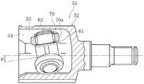
As shown in fig. 7a and 7b, the tripod type constant velocity universal joint 51 includes: an outer joint member 52 having three track grooves 53 extending in an axial direction at trisectional positions in a circumferential direction, and having roller guide surfaces 54 formed on opposing side walls of the track grooves 53; a tripod member 60 having trunnion journals 62 radially projecting from trisectional positions in the circumferential direction of a trunnion body portion 61; and a roller 70 rotatably attached around each trunnion journal 62 via a plurality of needle rollers 72, the roller 70 being accommodated in the track groove 53 of the outer joint member 52. The roller 70 has a spherical outer diameter surface 70a, and the spherical outer diameter surface 70a is guided by roller guide surfaces 54 formed on both side walls of the raceway groove 53 (see patent document 1).
Prior art documents
Patent document
Patent document 1: japanese patent No. 3947342
Disclosure of Invention
Problems to be solved by the invention
When the tripod type constant velocity universal joint 51 transmits a rotational force in a state where the joint has an operating angle θ as shown in fig. 8a, the rollers 70 and the roller guide surfaces 54 are in a mutually oblique relationship as shown in fig. 8 b. Since the roller guide surfaces 54 of the track grooves 53 are part of the cylindrical surfaces of the outer joint member 52 parallel to the axis, the rollers 70 move while being constrained by the roller guide surfaces 54 of the track grooves 53. As a result, sliding occurs between the roller guide surface 54 and the roller 70. The roller guide surface 54 is worn by this sliding, and if the wear is too large, vibration and noise of the vehicle body are caused. In order to reduce the wear, the spherical outer diameter surface 70a of the roller 70 is ground and then barreled.
Therefore, the roller 70 has a simple shape but is completed through a plurality of processing steps as shown in fig. 9a to 9 e. Specifically, in fig. 9a, the ring shape is formed by forging, and in fig. 9b, the inner and outer diameter surfaces and the chamfer are formed by turning. Thereafter, in fig. 9c, quenching and tempering are performed by heat treatment. After the heat treatment, the outer and inner diameter surfaces are finished by grinding in fig. 9d, and finally, barrel finished in fig. 9 e. Thus, the large number of machining processes increases the manufacturing cost and the time required for manufacturing. The present invention addresses this problem.
In view of the above-described problems, an object of the present invention is to provide a tripod constant velocity universal joint and a method of manufacturing the same, which can reduce manufacturing costs and improve productivity while maintaining the same function as a roller formed by a conventional machining method.
Means for solving the problems
In order to achieve the above object, the present invention has been made in an earnest study and verification focusing on various items shown below, and as a result, has a new concept of simplifying the machining process while maintaining the same function as that of a roller formed by a conventional machining method, and has completed the present invention.
(1) Possibility for analysis and simplification of the working process
(2) Combined action of turning and roller burnishing
(3) Influence degree of heat treatment deformation on function of coupler
As a technical means for achieving the above object, the present invention relates to a tripod type constant velocity universal joint including: an outer joint member having track grooves formed at trisectional positions in a circumferential direction and extending in an axial direction; a tripod member having a foot shaft radially protruding from a trisection position in a circumferential direction; and a roller rotatably mounted on the leg shaft, the roller being accommodated in the raceway groove,
the outer diameter surface of the roller is formed by a surface which is not subjected to grinding or cutting after heat treatment.
The present invention relating to a manufacturing method also relates to a method of manufacturing a tripod constant velocity universal joint, the tripod constant velocity universal joint including: an outer joint member having track grooves formed at trisectional positions in a circumferential direction and extending in an axial direction; a tripod member having a foot shaft radially protruding from a trisection position in a circumferential direction; and a roller rotatably attached to the leg shaft, the roller being accommodated in the raceway groove, wherein the roller manufacturing process does not include a process of grinding an outer diameter surface of the roller after heat treatment of the roller, and the roller manufacturing process includes: a step of turning the outer diameter surface of the roller by a formed turning tool; a step of heat-treating the roller after the turning; and performing a barrel burnishing process on the roller after the heat treatment.
According to the above configuration, it is possible to realize a tripod constant velocity universal joint and a method of manufacturing the same, which can reduce manufacturing cost and improve productivity while maintaining the same function as that of rollers formed by a conventional machining method. In the present specification and claims, the grinding process is a processing method in which a surface of an object is slightly removed by using a grindstone, and does not include a tumbling process, a barrel polishing process, or the like in which the object and a medium, a mixture, or the like are put in a container and the container is subjected to rotation and vibration to perform polishing. The cutting process is a processing method of cutting an object by using a cutting tool having a cutting edge such as a turning tool or a milling tool.
Specifically, in the former stage of the heat treatment, the outer diameter surface of the roller is a turning surface having no guide mark, and the spherical outer diameter surface of the finished product finished by the barrel finishing after the heat treatment has a surface roughness similar to that of the conventional product subjected to the grinding.
The roundness of the outer diameter surface of the roller is preferably 10 μm or more and 40 μm or less, and more preferably 10 μm or more and 30 μm or less. This enables the roller to maintain the same function as a roller formed by a conventional machining method. If the roundness of the outer diameter surface of the roller is larger than 40 μm, the sliding between the outer diameter surface of the roller and the roller guide surface adversely affects the life and durability. On the other hand, in order to suppress the circularity to less than 10 μm, the heat treatment cost is increased, which is not preferable.
The tripod type constant velocity universal joint is preferably a single-row roller type in which rollers are rotatably attached to the periphery of a cylindrical outer peripheral surface of a trunnion journal, which is a leg shaft of a tripod member, via a plurality of needle rollers. Thus, a tripod type constant velocity universal joint of lower cost can be realized.
Preferably, a step of performing a barrel burnishing process on the roller is provided after the step of performing the heat treatment on the roller. This makes it possible to remove scales generated by heat treatment while keeping the surface roughness of the outer diameter surface of the roller the same as that of conventional products.
Preferably, the step of heat-treating the roller includes a step of grinding an inner diameter surface of the roller. This eliminates the deformation caused by the heat treatment, thereby improving the rolling life.
Effects of the invention
According to the tripod constant velocity universal joint and the method of manufacturing the same of the present invention, it is possible to realize a tripod constant velocity universal joint and a method of manufacturing the same, which maintain the same function as that of the rollers formed by the conventional machining method, and which achieve a reduction in manufacturing cost and an improvement in productivity.
Drawings
Fig. 1a is a cross-sectional view showing a tripod-type constant velocity universal joint according to an embodiment of the present invention.
Fig. 1b is a longitudinal sectional view showing a tripod type constant velocity universal joint according to an embodiment of the present invention.
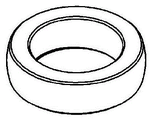
Fig. 2a is a schematic diagram showing a manufacturing process of the roller of the tripod constant velocity universal joint shown in fig. 1a and 1b, and shows a forging process.
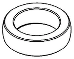
Fig. 2b is a schematic diagram showing a manufacturing process of the roller of the tripod constant velocity universal joint shown in fig. 1a and 1b, and shows a turning process.
Fig. 2c is a schematic diagram showing a manufacturing process of the rollers of the tripod constant velocity universal joint shown in fig. 1a and 1b, and showing a heat treatment.
Fig. 2d is a schematic diagram showing a manufacturing process of the roller of the tripod type constant velocity universal joint shown in fig. 1a and 1b, and shows a barrel burnishing process.
Fig. 3a is a side view schematically showing a state in which a spherical outer diameter surface of the roller of fig. 2b is turned.
Fig. 3b is a schematic plan view showing a state in which the spherical outer diameter surface of the roller of fig. 2b is turned.
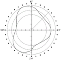
Fig. 4a is a schematic plan view showing a state where the roundness of the spherical outer surface of the roller is measured.
Fig. 4b is a side view schematically showing a state where the roundness of the spherical outer diameter surface of the roller is measured.
Fig. 5a shows the case of the triangular heat treatment distortion using the roundness measurement result obtained by the measurement method of fig. 4a and 4 b.
Fig. 5b shows the heat treatment distortion of the bag shape, using the roundness measurement results obtained by the measurement methods shown in fig. 4a and 4 b.
Fig. 6a is a schematic view for explaining an operating state of the roller, and shows the roller of the present embodiment.
Fig. 6b is a schematic view for explaining an operating state of a roller, and shows a roller formed by a conventional machining method.
Fig. 7a is a cross-sectional view showing a conventional tripod-type constant velocity universal joint.
Fig. 7b is a longitudinal sectional view showing a conventional tripod type constant velocity universal joint.
Fig. 8a is a partial longitudinal sectional view showing a state where the tripod type constant velocity universal joint of fig. 7a and 7b has an operating angle.
Fig. 8b is a perspective view showing a state of the roller and the roller guide surface of fig. 8 a.
Fig. 9a is a schematic diagram showing a manufacturing process of a roller of a conventional tripod constant velocity universal joint, and shows a forging process.
Fig. 9b is a schematic diagram showing a manufacturing process of a roller of a conventional tripod constant velocity universal joint, and shows a turning process.
Fig. 9c is a schematic diagram showing a manufacturing process of rollers of a conventional tripod constant velocity universal joint, and shows a heat treatment.
Fig. 9d is a schematic diagram showing a manufacturing process of a roller of a conventional tripod type constant velocity universal joint, and shows grinding.
Fig. 9e is a schematic diagram showing a manufacturing process of a roller of a conventional tripod type constant velocity universal joint, and shows a barrel burnishing process.
Detailed Description
An embodiment of a tripod constant velocity universal joint according to the present invention and an embodiment of a method of manufacturing the tripod constant velocity universal joint will be described with reference to fig. 1 to 6.
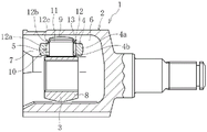
Fig. 1a is a cross-sectional view of a tripod type constant velocity universal joint according to an embodiment of the present invention, and fig. 1b is a longitudinal sectional view. As shown in the drawings, the tripod type constant velocity universal joint 1 of the present embodiment mainly includes: an outer joint member 2, a tripod member 3 as an inner joint member, spherical rollers 4, and needle rollers 5 as rolling elements. The outer joint member 2 has a hollow cup shape having three track grooves 6 extending in the axial direction at trisectional positions in the circumferential direction of the inner periphery thereof. A roller guide surface 7 is formed on the opposing side wall of each track groove 6. The roller guide surface 7 is formed by a part of the cylindrical surface, that is, a partial cylindrical surface. The spherical outer diameter surface 4a of the spherical roller 4 is guided by the roller pattern inner surface 7 of this shape.
The tripod member 3 is composed of a trunnion trunk 8 and trunnion journals 9 as leg shafts, and three trunnion journals 9 are formed so as to project radially from trisectional positions in the circumferential direction of the trunnion trunk 8. Each trunnion journal 9 includes a cylindrical outer peripheral surface 10 and an annular retainer groove 11 formed near the shaft end. The ball roller 4 is rotatably attached around a cylindrical outer peripheral surface 10 of the trunnion journal 9 via a plurality of needle rollers 5. The cylindrical outer peripheral surface 10 of the trunnion journal 9 forms an inner raceway surface of the needle roller 5. The inner circumferential surface 4b of the spherical roller 4 has a cylindrical shape and forms an outer raceway surface of the needle roller 5.
A retainer ring 13 is mounted via an outer washer 12 in a retainer ring groove 11 formed near the shaft end of the trunnion journal 9. The needle roller 5 is restricted from moving in the axial direction of the trunnion journal 9 by the root step of the trunnion journal 9 and the outer washer 12. The outer washer 12 is composed of a disk portion 12a extending in the radial direction of the trunnion journal 9 and a cylindrical portion 12b extending in the axial direction of the trunnion journal 9. The cylindrical portion 12b of the outer washer 12 has an outer diameter smaller than the inner circumferential surface 4b of the ball roller 4, and an outer end portion 12c of the cylindrical portion 12b is formed to have a diameter larger than the inner circumferential surface 4b of the ball roller 4 when viewed in the radial direction of the tripod member 3. Therefore, the ball roller 4 can move in the axial direction of the trunnion journal 9, and is prevented from falling off by the end portion 12 c.
The spherical rollers 4 rotatably attached to the trunnion journals 9 of the trunnion members 3 are rotatably guided by the roller guide surfaces 7 of the track grooves 6 of the outer joint member 2. With this configuration, relative axial displacement and angular displacement between the outer joint member 2 and the tripod member 3 are absorbed, and rotation is transmitted at a constant speed.
When the rotational force is transmitted in the state where the joint has the operating angle, the spherical roller 4 and the roller guide surface 7 are in a mutually oblique relationship, as in the case of fig. 8b described above. Further, since the roller guide surfaces 7 of the track grooves 6 are part of the cylindrical surface of the outer joint member 2 parallel to the axis, the spherical rollers 4 move while being constrained by the roller guide surfaces 7 of the track grooves 6. As a result, sliding occurs between the roller guide surface 7 and the roller 4.
The contact form between the spherical roller 4 and the roller guide surface 7 is generally two types, that is, angular contact and circular arc contact. Angular contact has a contact angle, contacting at two points. The circular arc contacts at one point.
The tripod type constant velocity universal joint according to the present embodiment is characterized in that the spherical outer diameter surface 4a of the spherical roller 4 is formed by a surface which has not been subjected to grinding or cutting after heat treatment. In addition, the characteristic structure of the embodiment of the method for manufacturing the tripod type constant velocity universal joint is that the roller manufacturing process does not include a step of grinding the spherical outer diameter surface 4a of the spherical roller 4, but includes a step of turning by a formed turning tool and a step of performing barrel burnishing.
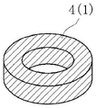
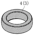
The manufacturing process of the spherical roller 4 will be described with reference to fig. 2a to 2 d. In fig. 2a, an annular blank 4(1) is formed by forging, and in fig. 2b, an inner and outer diameter surface, an end surface, and a chamfer are formed by turning to form a turned workpiece 4 (2). Thereafter, in fig. 2c, quenching and tempering are performed by heat treatment to form a heat treatment finished piece 4 (3). After the heat treatment, finish machining by grinding, which is used in a conventional machining method, is not performed, and as shown in fig. 2d, barrel finishing is performed to form a finished product 4.
The material of the ball rollers 4 is generally high carbon chromium bearing steel. The heat treatment of FIG. 2c is carried out by bulk quenching, and the hardness is about HRC 58-61.
In general, the barrel polishing is performed to remove burrs, scales, and the like, and is a polishing method in which an object and a mixture are put in a container, and the container is rotated to polish the object by a cutting action between the objects. By the barrel burnishing, scale formed by the heat treatment can be removed while the surface roughness of the outer diameter surface of the spherical roller 4 is made the same as that of the conventional one.
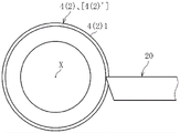
The turning process of fig. 2b is supplemented. From the forged annular blank 4(1) shown in fig. 2a, a spherical outer diameter surface 4(2)1, an inner diameter surface 4(2)2, an end surface 4(2)3, and chamfers 4(2)4, 4(2)5 shown in fig. 2b are turned. The spherical outer diameter surface 4(2)1 is turned by forming a turning tool.
Fig. 3a and 3b show turning of the spherical outer diameter surface 4(2)1 by a formed turning tool. Fig. 3a is a side view and fig. 3b is a top view. The inner and outer diameter surfaces, end surfaces, and the like of the blank 4(1) of the spherical roller shown in fig. 2a are turned, a cylindrical semi-finished product 4(2 ') (not shown) is clamped, and a turning tool 20 is fed in a direction perpendicular to the axis X of the semi-finished product 4 (2'), thereby turning the spherical outer diameter surface 4(2) 1. By the turning by the formed lathe tool 20, the spherical outer diameter surface 4(2)1 forms a turning surface free from a guide mark. Since the spherical rollers 4 of the tripod type constant velocity universal joint 1 of the present embodiment are not ground after the heat treatment, the size of the lathe-cut surface of the spherical outer diameter surface 4(2)1 is a finished product size in which the grinding removal amount is not provided.
The turning of the spherical outer diameter surface 4(2)1 by the formed turning tool 20 described above has the following unexpected advantages. The turned work piece 4(2) is subjected to the tumbling process of fig. 2d after the heat treatment of fig. 2 c. It is known that the surface roughness of the spherical outer diameter surface 4a of the finished product 4 finished by the barrel finishing can be made to be equivalent to that of a conventional product subjected to the grinding. As described above, it is verified that the surface roughness of the spherical outer surface 4a is improved by the combined action of the turning of the spherical outer surface 4(2)1 by the formed lathe tool 20 and the finish-machining of the barrel finishing, which is a key for enabling the analysis and simplification of the machining process.
The verification result of the surface roughness of the spherical outer diameter surface 4a is an attempt to verify the influence of the heat treatment distortion on the coupling function as a step below. The spherical roller 4 applied in the present embodiment is not ground after the heat treatment, and thus deformation due to the heat treatment remains. Therefore, the roundness of the spherical outer diameter surface 4a of the spherical roller 4 as a finished product was verified.
A method for measuring the roundness of the spherical outer diameter surface 4a of the spherical roller 4 applied to the present embodiment and the results thereof will be described with reference to fig. 4a, 4b, 5a, and 5 b. FIGS. 4a and 4b show a method for measuring roundnessFig. 4a is a plan view and fig. 4b is a side view. The roundness measuring machine used was TALYROND 265 manufactured by Tayloshon corporation, and the rotation speed of the main shaft was 6min-1The measurement is performed in the case of (1). As shown in fig. 4b, the measurement terminal 21 is brought into contact with the center of the spherical outer diameter surface 4a of the spherical roller 4 to perform measurement.
Fig. 5a and 5b show typical examples of the measurement results. Fig. 5a shows the case of the heat treatment deformation of the triangular shape, and fig. 5b shows the case of the heat treatment deformation of the bag shape having convex portions at two locations. The circularities of both were 20 μm.
[ example 1]
The spherical rollers 4 of the example, which were not ground after the heat treatment, were assembled to the tripod type constant velocity universal joint 1, and the joint characteristics were evaluated. As an example, spherical rollers 4 having various circularities such as a triangular shape (see fig. 5a) or a bag shape (see fig. 5b) with a circularity within a range of 10 to 30 μm in which heat treatment deformation remains are prepared. The conventional article is a spherical roller having a roundness of less than 5 μm after grinding.
[ characteristic evaluation test ]
In the characteristic evaluation test described below, a tripod type constant velocity universal joint of size ETJ75, referred to as NTN, was used as a test specimen.
< high load durability test >
Bench tests were performed as accelerated evaluation of the coupling life. The load torque is set to a high load condition matching the coupling size, and the working angle is set to the maximum common angle used in a three-ball-and-pin-series coupling. The number of samples n was 4, and all of them were evaluated to achieve the target. From this result, the possibility that the life is excellent is high, which is determined from the deviation from the life of the conventional article.
< induced thrust measurement >
(test conditions)
Torque: 300Nm
Number of revolutions: 300min-1
The working angle: 0 degree to 15 degree
It was confirmed through bench tests that the induced thrust is of such a degree that it does not affect the vibration during acceleration of the vehicle. As in the prior art.
< static excitation sliding resistance >
(test conditions)
Torque: 150Nm
Amplitude: plus or minus 0.02mm
The static excitation sliding resistance was confirmed by bench tests to such an extent that it did not affect the idling vibration. As in the prior art.
The evaluation results are shown in table 1. The evaluation results of the coupling characteristics in table 1 are shown below. The various spherical rollers 4 described above in table 1 all gave the same results and are therefore collectively described.
Very good: excellent,. smallcircle: has no problem in practical use
[ TABLE 1]

From the evaluation results in table 1, it was confirmed that the tripod-type constant velocity universal joint 1 incorporating the spherical rollers 4 of the example had no problem in actual use in terms of rolling characteristics and sliding characteristics. Further, unexpected effects more excellent than those of conventional products can be confirmed with respect to the lubrication characteristics and the life characteristics.
The reason why the above-described evaluation results are obtained is discussed. Next, description will be given with reference to fig. 6a and 6 b. Fig. 6a is a schematic view showing an operating state of a ball roller to which the present embodiment is applied, and fig. 6b is a schematic view showing an operating state of a conventional ball roller. The spherical roller of fig. 6a illustrates a case of heat treatment deformation in a triangular shape, and the amount of deformation is exaggeratedly shown for easy understanding.
(1) Spherical roller with uniform roundness and uniform dispersion of contact area
The roundness of the spherical outer surface 70a of the conventional spherical roller 70 subjected to grinding shown in fig. 6b is 4 μm or less, and the variation in the outer diameter due to the phase is small. Therefore, when the swing motion indicated by the hollow arrow is performed, the ball roller 70 is continuously subjected to a load within a certain range of the spherical outer diameter surface 70a, and therefore, damage is likely to progress, which is disadvantageous in terms of life. The above-mentioned swinging movement is supplemented. When the tripod type constant velocity universal joint rotates at the operating angle θ, the movement such as wiper that inclines from the inclined state of the trunnion journal 62 shown in fig. 8a to the opposite side is repeated every rotation. This motion is referred to as a wobbling motion. The same applies to the following embodiments.
In contrast to the conventional material described above, the spherical outer diameter surface 4a of the spherical roller 4 applied to the present embodiment shown in fig. 6a, which is not ground after the heat treatment, has a large roundness of 10 to 30 μm, and a difference in outer diameter occurs due to the phase. Due to the difference in the outer diameter caused by the phase, the spherical roller 4 of the present embodiment varies the rolling resistance between the spherical roller 4 and the roller guide surface 7 due to the phase, and the movement changes during the swing movement (outlined arrow), and the spherical roller 4 moves with the entire outer circumference using the spherical outer diameter surface 4a, and the dispersion and the balance of the contact area are achieved, which is advantageous in terms of the life.
Further, in the case of the spherical roller 4 of the present embodiment in which the grinding process is not performed after the heat treatment when the direction of the load of the driving torque is switched and the spherical roller 4 is in contact with the opposite roller guide surface 7, the roller shape in contact with the roller guide surface 7 is not constant and is unstable, and therefore, when the spherical roller 4 is in contact with the opposite roller guide surface 7, the spherical roller 4 is easily rotated to form a movement using the entire outer circumference of the spherical outer diameter surface 4a, thereby achieving a distributed balance of the contact area and being advantageous in terms of life.
(2) Roundness and rolling resistance of spherical roller
In the case of the spherical roller 4 of the present embodiment, which is not ground after the heat treatment, the outer periphery of the roller is longer than the conventional grinding-processed roller 70. Therefore, the spherical roller 4 of the present embodiment has a small rotation angle of the roller with respect to the same sliding amount. When the rotation angle is small, the amount of rolling of the needle rollers 5 on the trunnion journals 9 decreases, and rolling resistance decreases, which is advantageous in terms of life.
(3) Turning surface without guide mark
In addition, since the turning surface without a guide mark and the barrel finishing are combined to obtain the same surface roughness as the conventional spherical roller 70 subjected to the grinding process, the spherical roller 4 of the present embodiment can maintain the wear resistance and the durability.
From the above discussion and the evaluation results of table 1 for examples having a circularity of 10 to 30 μm, it was concluded that there was no problem in actual use until the upper limit of the circularity of 40 μm was reached, taking into account several influences in terms of lubrication and life. In order to suppress the circularity to less than 10 μm, the heat treatment cost is increased, which is not preferable.
As described above, the tripod type constant velocity universal joint according to the present embodiment is characterized in that the spherical outer diameter surface 4a of the spherical roller 4 is formed by a surface which has not been subjected to grinding or cutting after heat treatment. In addition, the characteristic structure of the embodiment of the method of manufacturing the tripod type constant velocity universal joint is that the roller manufacturing process does not include a process of grinding the spherical outer diameter surface 4a of the spherical roller 4, but includes a process of turning by a formed turning tool and a process of performing barrel burnishing. Thus, it is possible to realize a tripod type constant velocity universal joint and a method of manufacturing the same, which can reduce manufacturing cost and improve productivity while maintaining the same function as that of a roller formed by a conventional machining method.
The tripod type constant velocity universal joint according to the present embodiment is exemplified by a single-row roller type constant velocity universal joint in which rollers are rotatably attached via a plurality of needle rollers to the periphery of the cylindrical outer peripheral surface of the trunnion as the tripod member, but the present invention is not limited thereto, and can also be applied to a double-row roller type constant velocity universal joint in which roller cartridges each including an inner race, a needle roller, and a roller are attached to the trunnion of the tripod member.
The present invention is not limited to the above-described embodiments, and it is needless to say that the present invention can be implemented in various forms without departing from the gist of the present invention, and the scope of the present invention is indicated by the scope of the claims, and includes all modifications equivalent to the meaning described in the scope of the claims and the scope thereof.
Description of the reference numerals
1 tripod constant velocity universal joint
2 outer coupling member
3 three ball pin component
4 ball roller
4a spherical outside diameter surface
5 needle roller
6 raceway groove
7 roller guide surface
8 trunnion trunk part
9 trunnion journal
10 cylindrical outer peripheral surface
20-shaped turning tool
Claims (4)
1. A tripod type constant velocity universal joint comprising:
an outer joint member having track grooves formed at trisection positions in a circumferential direction and extending in an axial direction;
a tripod member having a leg shaft radially protruding from a trisection position in a circumferential direction; and
a roller rotatably mounted on the leg shaft,
the roller is accommodated in the raceway groove,
the tripod-type constant velocity universal joint is characterized in that,
the rollers are subjected to a quenching and tempering heat treatment,
at the stage before the heat treatment, the outer diameter surface of the roller is formed by a turning surface turned by a forming turning tool,
the outer diameter surface of the roller is formed by a surface subjected to the barrel burnishing without performing the grinding or cutting after the heat treatment,
the roundness of the outer diameter surface of the roller is 10 [ mu ] m or more and 40 [ mu ] m or less.
2. A tripod constant velocity universal joint according to claim 1,
the roller is rotatably attached to the periphery of a cylindrical outer peripheral surface of a trunnion journal as the leg shaft via a plurality of needle rollers.
3. A method of manufacturing a tripod constant velocity universal joint, the tripod constant velocity universal joint comprising:
an outer joint member having track grooves formed at trisection positions in a circumferential direction and extending in an axial direction;
a tripod member having a leg shaft radially protruding from a trisection position in a circumferential direction; and
a roller rotatably mounted on the leg shaft,
the roller is accommodated in the raceway groove,
the method of manufacturing a tripod-type constant velocity universal joint is characterized in that,
the roller manufacturing process does not include a step of grinding the outer diameter surface of the roller after the heat treatment of the roller,
the manufacturing process of the roller comprises the following steps:
a step of turning the outer diameter surface of the roller by a formed turning tool;
a step of performing quenching and tempering heat treatment on the roller after the turning; and
a step of performing barrel burnishing on the roller after the heat treatment,
the roundness of the outer diameter surface of the roller is 10 [ mu ] m or more and 40 [ mu ] m or less.
4. A method of manufacturing a tripod-type constant velocity universal joint according to claim 3,
the method includes a step of grinding an inner diameter surface of the roller after the step of heat-treating the roller.
Applications Claiming Priority (3)
| Application Number | Priority Date | Filing Date | Title |
|---|---|---|---|
| JP2014154978A JP6382014B2 (en) | 2014-07-30 | 2014-07-30 | Tripod type constant velocity universal joint and manufacturing method thereof |
| JP2014-154978 | 2014-07-30 | ||
| PCT/JP2015/068807 WO2016017345A1 (en) | 2014-07-30 | 2015-06-30 | Tripod constant velocity universal joint and method for manufacturing same |
Publications (2)
| Publication Number | Publication Date |
|---|---|
| CN106536955A CN106536955A (en) | 2017-03-22 |
| CN106536955B true CN106536955B (en) | 2022-07-22 |
Family
ID=55217249
Family Applications (1)
| Application Number | Title | Priority Date | Filing Date |
|---|---|---|---|
| CN201580038588.2A Active CN106536955B (en) | 2014-07-30 | 2015-06-30 | Tripod type constant velocity universal joint and method for manufacturing the same |
Country Status (5)
| Country | Link |
|---|---|
| US (1) | US10655677B2 (en) |
| EP (1) | EP3176453B1 (en) |
| JP (1) | JP6382014B2 (en) |
| CN (1) | CN106536955B (en) |
| WO (1) | WO2016017345A1 (en) |
Families Citing this family (1)
| Publication number | Priority date | Publication date | Assignee | Title |
|---|---|---|---|---|
| JP2021055794A (en) * | 2019-10-01 | 2021-04-08 | Ntn株式会社 | Machined product |
Citations (4)
| Publication number | Priority date | Publication date | Assignee | Title |
|---|---|---|---|---|
| JP2000081050A (en) * | 1998-09-08 | 2000-03-21 | Nippon Seiko Kk | Cylindrical roller for tripod type constant velocity joint and manufacture thereof |
| JP2002235753A (en) * | 2001-02-09 | 2002-08-23 | Ntn Corp | Shell-type roller bearing |
| CN1837631A (en) * | 2005-03-24 | 2006-09-27 | Ntn株式会社 | Tripod constant velocity universal joint |
| JP2007040503A (en) * | 2005-08-05 | 2007-02-15 | Ntn Corp | Collared roller bearing |
Family Cites Families (19)
| Publication number | Priority date | Publication date | Assignee | Title |
|---|---|---|---|---|
| JPS5333084U (en) * | 1976-08-28 | 1978-03-23 | ||
| JPS5333084A (en) | 1976-09-09 | 1978-03-28 | Agency Of Ind Science & Technol | Silicon solar battery |
| JP2635083B2 (en) * | 1988-03-02 | 1997-07-30 | 新日本工機株式会社 | Lathe and lathe processing method |
| JPH06249317A (en) * | 1993-02-26 | 1994-09-06 | Ntn Corp | Thread groove forming method for ball screw |
| CN1178571A (en) * | 1996-02-05 | 1998-04-08 | 株式会社Ntn | Tri-pot constant velocity universal joint |
| US6390924B1 (en) * | 1999-01-12 | 2002-05-21 | Ntn Corporation | Power transmission shaft and constant velocity joint |
| JP2000256694A (en) * | 1999-03-11 | 2000-09-19 | Ntn Corp | Tripod-type constant-velocity universal joint and grease for this joint |
| JP4230063B2 (en) * | 1999-08-18 | 2009-02-25 | 株式会社リコー | Rotating body molding method and molding die |
| JP2001300675A (en) * | 2000-02-18 | 2001-10-30 | Nsk Ltd | Screw form rolling die, and manufacturing method thereof |
| JP3947342B2 (en) | 2000-05-22 | 2007-07-18 | Ntn株式会社 | Tripod type constant velocity universal joint |
| JP2002213477A (en) * | 2001-01-16 | 2002-07-31 | Ntn Corp | Tripod constant velocity universal joint |
| US6708544B2 (en) | 2001-02-16 | 2004-03-23 | Nsk Ltd. | Thread rolling die and process for the production thereof |
| JP2004100754A (en) * | 2002-09-06 | 2004-04-02 | Nsk Ltd | Finishing method for smooth surface of outer ring inner surface of bearing device and bearing device finished by the same method |
| JP2004360830A (en) * | 2003-06-05 | 2004-12-24 | Ntn Corp | Constant velocity universal joint and its manufacturing method |
| JP4361351B2 (en) * | 2003-11-14 | 2009-11-11 | Ntn株式会社 | Tripod type constant velocity universal joint |
| WO2007148487A1 (en) * | 2006-06-23 | 2007-12-27 | Ntn Corporation | Constant velocity universal joint, and drive shaft and drive wheel bearing using the same |
| JP2008275095A (en) * | 2007-05-01 | 2008-11-13 | Ntn Corp | Ball screw and manufacturing method thereof |
| KR101405191B1 (en) * | 2012-11-15 | 2014-06-10 | 기아자동차 주식회사 | Continuous velocity joint |
| CN103331456A (en) * | 2013-06-26 | 2013-10-02 | 上海斐赛轴承科技有限公司 | Machining method of rolling bearing formed by whole and precise hard turning and molding of sleeve ring |
-
2014
- 2014-07-30 JP JP2014154978A patent/JP6382014B2/en active Active
-
2015
- 2015-06-30 WO PCT/JP2015/068807 patent/WO2016017345A1/en active Application Filing
- 2015-06-30 US US15/326,704 patent/US10655677B2/en active Active
- 2015-06-30 EP EP15827592.5A patent/EP3176453B1/en active Active
- 2015-06-30 CN CN201580038588.2A patent/CN106536955B/en active Active
Patent Citations (4)
| Publication number | Priority date | Publication date | Assignee | Title |
|---|---|---|---|---|
| JP2000081050A (en) * | 1998-09-08 | 2000-03-21 | Nippon Seiko Kk | Cylindrical roller for tripod type constant velocity joint and manufacture thereof |
| JP2002235753A (en) * | 2001-02-09 | 2002-08-23 | Ntn Corp | Shell-type roller bearing |
| CN1837631A (en) * | 2005-03-24 | 2006-09-27 | Ntn株式会社 | Tripod constant velocity universal joint |
| JP2007040503A (en) * | 2005-08-05 | 2007-02-15 | Ntn Corp | Collared roller bearing |
Also Published As
| Publication number | Publication date |
|---|---|
| EP3176453B1 (en) | 2019-09-04 |
| US10655677B2 (en) | 2020-05-19 |
| EP3176453A4 (en) | 2018-04-25 |
| JP6382014B2 (en) | 2018-08-29 |
| WO2016017345A1 (en) | 2016-02-04 |
| JP2016031132A (en) | 2016-03-07 |
| US20180335076A1 (en) | 2018-11-22 |
| EP3176453A1 (en) | 2017-06-07 |
| CN106536955A (en) | 2017-03-22 |
Similar Documents
| Publication | Publication Date | Title |
|---|---|---|
| KR101551316B1 (en) | Bearing roller, bearing, and bearing roller processing method | |
| JP2018202578A (en) | Superfinishing method for groove and manufacturing method for bearing | |
| CN107466341B (en) | Tripod type constant velocity universal joint | |
| CN106536955B (en) | Tripod type constant velocity universal joint and method for manufacturing the same | |
| CN113195915A (en) | Tripod type constant velocity universal joint | |
| CN102859219A (en) | Tripod constant velocity universal joint | |
| CN105899831B (en) | Improved torque transmitting joint and joint member, method of manufacture and method of inspection | |
| JP2008240825A (en) | Machining method, trunnion and tripod type constant velocity universal joint | |
| KR102034484B1 (en) | Manufacturing method for tapered roller, and tapered roller bearing | |
| JP5747723B2 (en) | Trunnion of toroidal type continuously variable transmission and processing method thereof | |
| US11401973B2 (en) | Thrust roller bearing | |
| JP2000145794A (en) | Ultra-high speed, high rigidity rolling bearing | |
| KR20170138485A (en) | Manufacturing method of rotating body for rolling bearings | |
| US20110118036A1 (en) | Inner joint member for constant velocity universal joint, manufacturing method therefor, and constant velocity universal joint | |
| JP2018200109A (en) | Tripod-type constant velocity universal joint | |
| JP6843786B2 (en) | Manufacturing method of bearing parts, rolling bearings, and bearing parts | |
| CN111373168B (en) | Rolling member, bearing, and method for manufacturing same | |
| JP2010261559A (en) | Trunnion for tripod type constant velocity universal coupling, and tripod type constant velocity universal coupling | |
| JP5779118B2 (en) | Rolling contact parts, rolling bearings, universal joints, and manufacturing methods thereof | |
| JPH01257502A (en) | Center hole machining device for crankshaft | |
| JP2002168256A (en) | Rolling bearing and manufacturing method therefor | |
| JP2007100835A (en) | Trunnion for tripod type constant velocity universal joint and its manufacturing method | |
| JP2009002388A (en) | Tripod constant velocity universal joint | |
| JP2021055794A (en) | Machined product | |
| CN117836530A (en) | Tripod constant velocity universal joint |
Legal Events
| Date | Code | Title | Description |
|---|---|---|---|
| C06 | Publication | ||
| PB01 | Publication | ||
| SE01 | Entry into force of request for substantive examination | ||
| SE01 | Entry into force of request for substantive examination | ||
| GR01 | Patent grant | ||
| GR01 | Patent grant |