CN1064659C - Enhanced oxidation of organic chemicals - Google Patents
Enhanced oxidation of organic chemicals Download PDFInfo
- Publication number
- CN1064659C CN1064659C CN95105721A CN95105721A CN1064659C CN 1064659 C CN1064659 C CN 1064659C CN 95105721 A CN95105721 A CN 95105721A CN 95105721 A CN95105721 A CN 95105721A CN 1064659 C CN1064659 C CN 1064659C
- Authority
- CN
- China
- Prior art keywords
- oxygen
- liquid
- impeller
- drainage tube
- flow
- Prior art date
- Legal status (The legal status is an assumption and is not a legal conclusion. Google has not performed a legal analysis and makes no representation as to the accuracy of the status listed.)
- Expired - Fee Related
Links
Images


Classifications
-
- B—PERFORMING OPERATIONS; TRANSPORTING
- B01—PHYSICAL OR CHEMICAL PROCESSES OR APPARATUS IN GENERAL
- B01J—CHEMICAL OR PHYSICAL PROCESSES, e.g. CATALYSIS OR COLLOID CHEMISTRY; THEIR RELEVANT APPARATUS
- B01J19/00—Chemical, physical or physico-chemical processes in general; Their relevant apparatus
-
- C—CHEMISTRY; METALLURGY
- C07—ORGANIC CHEMISTRY
- C07B—GENERAL METHODS OF ORGANIC CHEMISTRY; APPARATUS THEREFOR
- C07B33/00—Oxidation in general
-
- B—PERFORMING OPERATIONS; TRANSPORTING
- B01—PHYSICAL OR CHEMICAL PROCESSES OR APPARATUS IN GENERAL
- B01F—MIXING, e.g. DISSOLVING, EMULSIFYING OR DISPERSING
- B01F23/00—Mixing according to the phases to be mixed, e.g. dispersing or emulsifying
- B01F23/20—Mixing gases with liquids
-
- B—PERFORMING OPERATIONS; TRANSPORTING
- B01—PHYSICAL OR CHEMICAL PROCESSES OR APPARATUS IN GENERAL
- B01F—MIXING, e.g. DISSOLVING, EMULSIFYING OR DISPERSING
- B01F23/00—Mixing according to the phases to be mixed, e.g. dispersing or emulsifying
- B01F23/20—Mixing gases with liquids
- B01F23/23—Mixing gases with liquids by introducing gases into liquid media, e.g. for producing aerated liquids
- B01F23/233—Mixing gases with liquids by introducing gases into liquid media, e.g. for producing aerated liquids using driven stirrers with completely immersed stirring elements
- B01F23/2334—Mixing gases with liquids by introducing gases into liquid media, e.g. for producing aerated liquids using driven stirrers with completely immersed stirring elements provided with stationary guiding means surrounding at least partially the stirrer
- B01F23/23341—Mixing gases with liquids by introducing gases into liquid media, e.g. for producing aerated liquids using driven stirrers with completely immersed stirring elements provided with stationary guiding means surrounding at least partially the stirrer with tubes surrounding the stirrer
-
- B—PERFORMING OPERATIONS; TRANSPORTING
- B01—PHYSICAL OR CHEMICAL PROCESSES OR APPARATUS IN GENERAL
- B01F—MIXING, e.g. DISSOLVING, EMULSIFYING OR DISPERSING
- B01F23/00—Mixing according to the phases to be mixed, e.g. dispersing or emulsifying
- B01F23/20—Mixing gases with liquids
- B01F23/23—Mixing gases with liquids by introducing gases into liquid media, e.g. for producing aerated liquids
- B01F23/233—Mixing gases with liquids by introducing gases into liquid media, e.g. for producing aerated liquids using driven stirrers with completely immersed stirring elements
- B01F23/2336—Mixing gases with liquids by introducing gases into liquid media, e.g. for producing aerated liquids using driven stirrers with completely immersed stirring elements characterised by the location of the place of introduction of the gas relative to the stirrer
- B01F23/23362—Mixing gases with liquids by introducing gases into liquid media, e.g. for producing aerated liquids using driven stirrers with completely immersed stirring elements characterised by the location of the place of introduction of the gas relative to the stirrer the gas being introduced under the stirrer
-
- B—PERFORMING OPERATIONS; TRANSPORTING
- B01—PHYSICAL OR CHEMICAL PROCESSES OR APPARATUS IN GENERAL
- B01F—MIXING, e.g. DISSOLVING, EMULSIFYING OR DISPERSING
- B01F23/00—Mixing according to the phases to be mixed, e.g. dispersing or emulsifying
- B01F23/20—Mixing gases with liquids
- B01F23/23—Mixing gases with liquids by introducing gases into liquid media, e.g. for producing aerated liquids
- B01F23/2366—Parts; Accessories
- B01F23/2368—Mixing receptacles, e.g. tanks, vessels or reactors, being completely closed, e.g. hermetically closed
-
- B—PERFORMING OPERATIONS; TRANSPORTING
- B01—PHYSICAL OR CHEMICAL PROCESSES OR APPARATUS IN GENERAL
- B01F—MIXING, e.g. DISSOLVING, EMULSIFYING OR DISPERSING
- B01F27/00—Mixers with rotary stirring devices in fixed receptacles; Kneaders
- B01F27/80—Mixers with rotary stirring devices in fixed receptacles; Kneaders with stirrers rotating about a substantially vertical axis
- B01F27/92—Mixers with rotary stirring devices in fixed receptacles; Kneaders with stirrers rotating about a substantially vertical axis with helices or screws
- B01F27/921—Mixers with rotary stirring devices in fixed receptacles; Kneaders with stirrers rotating about a substantially vertical axis with helices or screws with helices centrally mounted in the receptacle
- B01F27/9211—Mixers with rotary stirring devices in fixed receptacles; Kneaders with stirrers rotating about a substantially vertical axis with helices or screws with helices centrally mounted in the receptacle the helices being surrounded by a guiding tube
-
- B—PERFORMING OPERATIONS; TRANSPORTING
- B01—PHYSICAL OR CHEMICAL PROCESSES OR APPARATUS IN GENERAL
- B01J—CHEMICAL OR PHYSICAL PROCESSES, e.g. CATALYSIS OR COLLOID CHEMISTRY; THEIR RELEVANT APPARATUS
- B01J19/00—Chemical, physical or physico-chemical processes in general; Their relevant apparatus
- B01J19/18—Stationary reactors having moving elements inside
- B01J19/1868—Stationary reactors having moving elements inside resulting in a loop-type movement
- B01J19/1875—Stationary reactors having moving elements inside resulting in a loop-type movement internally, i.e. the mixture circulating inside the vessel such that the upwards stream is separated physically from the downwards stream(s)
-
- B—PERFORMING OPERATIONS; TRANSPORTING
- B01—PHYSICAL OR CHEMICAL PROCESSES OR APPARATUS IN GENERAL
- B01J—CHEMICAL OR PHYSICAL PROCESSES, e.g. CATALYSIS OR COLLOID CHEMISTRY; THEIR RELEVANT APPARATUS
- B01J19/00—Chemical, physical or physico-chemical processes in general; Their relevant apparatus
- B01J19/18—Stationary reactors having moving elements inside
- B01J19/20—Stationary reactors having moving elements inside in the form of helices, e.g. screw reactors
-
- B—PERFORMING OPERATIONS; TRANSPORTING
- B01—PHYSICAL OR CHEMICAL PROCESSES OR APPARATUS IN GENERAL
- B01J—CHEMICAL OR PHYSICAL PROCESSES, e.g. CATALYSIS OR COLLOID CHEMISTRY; THEIR RELEVANT APPARATUS
- B01J31/00—Catalysts comprising hydrides, coordination complexes or organic compounds
- B01J31/02—Catalysts comprising hydrides, coordination complexes or organic compounds containing organic compounds or metal hydrides
- B01J31/12—Catalysts comprising hydrides, coordination complexes or organic compounds containing organic compounds or metal hydrides containing organo-metallic compounds or metal hydrides
-
- C—CHEMISTRY; METALLURGY
- C07—ORGANIC CHEMISTRY
- C07C—ACYCLIC OR CARBOCYCLIC COMPOUNDS
- C07C51/00—Preparation of carboxylic acids or their salts, halides or anhydrides
- C07C51/16—Preparation of carboxylic acids or their salts, halides or anhydrides by oxidation
- C07C51/21—Preparation of carboxylic acids or their salts, halides or anhydrides by oxidation with molecular oxygen
- C07C51/255—Preparation of carboxylic acids or their salts, halides or anhydrides by oxidation with molecular oxygen of compounds containing six-membered aromatic rings without ring-splitting
- C07C51/265—Preparation of carboxylic acids or their salts, halides or anhydrides by oxidation with molecular oxygen of compounds containing six-membered aromatic rings without ring-splitting having alkyl side chains which are oxidised to carboxyl groups
-
- C—CHEMISTRY; METALLURGY
- C07—ORGANIC CHEMISTRY
- C07C—ACYCLIC OR CARBOCYCLIC COMPOUNDS
- C07C63/00—Compounds having carboxyl groups bound to a carbon atoms of six-membered aromatic rings
- C07C63/14—Monocyclic dicarboxylic acids
- C07C63/15—Monocyclic dicarboxylic acids all carboxyl groups bound to carbon atoms of the six-membered aromatic ring
- C07C63/26—1,4 - Benzenedicarboxylic acid
-
- B—PERFORMING OPERATIONS; TRANSPORTING
- B01—PHYSICAL OR CHEMICAL PROCESSES OR APPARATUS IN GENERAL
- B01F—MIXING, e.g. DISSOLVING, EMULSIFYING OR DISPERSING
- B01F23/00—Mixing according to the phases to be mixed, e.g. dispersing or emulsifying
- B01F23/20—Mixing gases with liquids
- B01F23/23—Mixing gases with liquids by introducing gases into liquid media, e.g. for producing aerated liquids
- B01F23/233—Mixing gases with liquids by introducing gases into liquid media, e.g. for producing aerated liquids using driven stirrers with completely immersed stirring elements
- B01F23/2336—Mixing gases with liquids by introducing gases into liquid media, e.g. for producing aerated liquids using driven stirrers with completely immersed stirring elements characterised by the location of the place of introduction of the gas relative to the stirrer
- B01F23/23364—Mixing gases with liquids by introducing gases into liquid media, e.g. for producing aerated liquids using driven stirrers with completely immersed stirring elements characterised by the location of the place of introduction of the gas relative to the stirrer the gas being introduced between the stirrer elements
-
- B—PERFORMING OPERATIONS; TRANSPORTING
- B01—PHYSICAL OR CHEMICAL PROCESSES OR APPARATUS IN GENERAL
- B01F—MIXING, e.g. DISSOLVING, EMULSIFYING OR DISPERSING
- B01F23/00—Mixing according to the phases to be mixed, e.g. dispersing or emulsifying
- B01F23/20—Mixing gases with liquids
- B01F23/23—Mixing gases with liquids by introducing gases into liquid media, e.g. for producing aerated liquids
- B01F23/237—Mixing gases with liquids by introducing gases into liquid media, e.g. for producing aerated liquids characterised by the physical or chemical properties of gases or vapours introduced in the liquid media
- B01F23/2376—Mixing gases with liquids by introducing gases into liquid media, e.g. for producing aerated liquids characterised by the physical or chemical properties of gases or vapours introduced in the liquid media characterised by the gas being introduced
- B01F23/23761—Aerating, i.e. introducing oxygen containing gas in liquids
- B01F23/237612—Oxygen
-
- B—PERFORMING OPERATIONS; TRANSPORTING
- B01—PHYSICAL OR CHEMICAL PROCESSES OR APPARATUS IN GENERAL
- B01F—MIXING, e.g. DISSOLVING, EMULSIFYING OR DISPERSING
- B01F27/00—Mixers with rotary stirring devices in fixed receptacles; Kneaders
- B01F27/05—Stirrers
- B01F27/11—Stirrers characterised by the configuration of the stirrers
- B01F27/114—Helically shaped stirrers, i.e. stirrers comprising a helically shaped band or helically shaped band sections
- B01F27/1144—Helically shaped stirrers, i.e. stirrers comprising a helically shaped band or helically shaped band sections with a plurality of blades following a helical path on a shaft or a blade support
-
- B—PERFORMING OPERATIONS; TRANSPORTING
- B01—PHYSICAL OR CHEMICAL PROCESSES OR APPARATUS IN GENERAL
- B01F—MIXING, e.g. DISSOLVING, EMULSIFYING OR DISPERSING
- B01F27/00—Mixers with rotary stirring devices in fixed receptacles; Kneaders
- B01F27/05—Stirrers
- B01F27/11—Stirrers characterised by the configuration of the stirrers
- B01F27/19—Stirrers with two or more mixing elements mounted in sequence on the same axis
- B01F27/192—Stirrers with two or more mixing elements mounted in sequence on the same axis with dissimilar elements
Abstract
Organic chemical oxidation reactions are carried out using pure or nearly pure oxygen and evaporative cooling. Advantageous operating results are achieved thereby, and the oxidation of organic chemicals resulting in the production of solid products or byproducts is facilitated by obviating the need for direct contact heat exchange surfaces that become coated with solid products or byproducts.
Description
The present invention relates to the mixing of gas and liquid.More particularly, the present invention relates to pure or approaching pure oxygen oxidation of organic compounds.
Oxidation products or by product with the solid matter form in reactor in the sedimentary oxidation of organic compounds reaction, it is very convenient to use direct contact cooling (for example using spiral coil cooling tube) to remove reaction heat.But the some parts in reaction mixture is in the three-phase system of sedimentary solid phase, and the precipitation of solid on heating surface can reduce this surperficial heat-transfer capability rapidly.In addition, in the oxidation of organic compounds reaction of height heat release, for the surface-area of removing the required heating surface of reaction heat may be quite big with respect to reactor volume.
Most of industrial organic compound liquid-phase oxidations are carried out as oxygen source easily with air.In this method for oxidation, the inert nitrogen component in the feeding air has removed a part of volatile constituent in the reaction mixture.This because evaporative removal the cooling effect that causes of latent heat, balance the heat that discharges of oxidizing reaction.For the excess air of giving determined number, perhaps flow through the inert gas of oxidation reactor, there is certain relation between the working pressure when the temperature of oxidation reactor and oxidizing reaction are carried out.This relation between temperature of reaction and the pressure depends on the composition of reaction mixture and the volume of used excess air.Transpiration cooling based on air generally all needs higher relatively pressure and temperature condition for any specified oxidation of organic compounds.
Fed feeding air in the reactor before being blown in the reactor, must be compressed to the working pressure of a little higher than reactor of pressure earlier through pipe or other submergent entry nozzle.When air filled cavity is disperseed and passes the liquid phase circulation time, the oxygen concn of bubble reduces owing to the oxygen dissolving with organic compound reaction in the liquid phase.Air filled cavity disengages from liquid phase and accumulates in reactor head, forms the successive gas phase.This top gas phase has constituted waste gas, and it must be drained so that for fresh feeding air provides the space, will keep enough gaseous storage amount to promote desirable oxygen by shifting in containing the organic compound liquid phase in the feeding air simultaneously.
Be the possibility of avoiding catching fire and exploding, the oxygen concentration in the reactor head gas space must keep below flammability limit.For this reason, oxygen concn must keep below 8-9% (volume).Be more typically, the oxygen concn in the gas space keeps below 5% (volume) so that the safe clearance that is lower than flammability limit to be provided.So in a well-beaten tank reactor, the mean concns of undissolved oxygen must be lower than 5% in the recirculated air bubble, be nonflammable so that guarantee to accumulate in the mean concns of the interior oxygen of gas in the reactor head space.
Oxygen concn in the gas space and feeding air enter the speed of reactor and the oxygen in the feeding air owing to the speed that consumes with oxidized organic compound reaction is relevant.For most of liquid phase oxidation reactions, the speed that the wastage in bulk or weight speed of oxygen is transferred in the liquid phase by the oxygen of (being in the bubble) in the gas phase determines.Because oxygen is divided into direct ratio in the transport velocity of oxygen and the gas phase, and dividing potential drop is proportional to the volume fraction of oxygen in gas phase, so the restriction of 5% oxygen has limited the mass transfer speed of oxygen widely in the gas phase above-mentioned, therefore also limited total oxidation rate of organic compound.
When air filled cavity during at the reactor internal recycle, solvent, water, volatile organic compounds (VOC) and byproduct gas are (as CO
2And CO) accumulate in the successive top gas space, and by emitting in the reactor.The total amount of leaving the volatile species of reactor with inertia discharging gas is directly proportional with total gas throughput, and the latter is proportional to air feed speed again.
In the U.S., federation, state and the geographic air quality standard that is applicable to specific production facility determined must therefrom remove the degree of these volatile species before discharging gas is discharged into the atmosphere.Solvent material is the useful component of oxidation style normally, so often with its condensation and be recycled in the reactor.Remaining organic compound usually from inertia discharging gas stripping come out, thereby form the waste liquid stream of stripper bottom.Some discharging gas processing system comprises also that in case of necessity the system of eliminating COx is to meet air quality standard.Because the material total amount that must remove the gas from discharging is directly proportional with the speed of air admission reactor, so discharge the size of gas disposal equipment and the quantity of the refuse that produces is directly proportional with air feed speed too in oxidising process.
Pure or approaching pure oxygen has a lot of potential advantages in these oxidation of organic compounds reactions.But, in oxidation system, add pure oxygen safely and effectively and need take special preventive measures, because the possibility of catching fire or exploding is arranged.The United States Patent (USP) U.S.P4 of Litz etc., 800,480 disclose a kind of extremely ideal liquid oxidation reactor (LOR) that is used for replacing popular response device system, popular response device system be improper for air with oxo during as raw material or efficient not high.This LOR system can go out bubble with a part from the top gas spatial isolation organic liquid composition recirculation flow so that improve the utilising efficiency of oxygen, avoids a large amount of gas loss to the top gas space simultaneously.Along with the recirculation and the oxygen of bubble shifts in liquid phase, the concentration of oxygen reduces in the bubble.The advantage of using the mass transfer aspect that pure oxygen provided also thereby reduce.
Carry out the oxidation of very fast organic compound for reaction, the utilising efficiency of oxygen is very high naturally.So, having consumed the oxygen of high percentage composition during the impeller unit that in first by the LOR system, uses, the superiority subsequently by impeller unit the time aspect the mass transfer reduces greatly.For this type systematic, do not wish alveolate recirculation.In addition, because the impeller of this downward pumping of using in the LOR system that Litz etc. are introduced and the essence of drainage tube on every side (draft tube), the gas of the significant volume in the drainage tube can make mixer apparatus cavitation erosion (cavitate) occur.If produce this cavitation erosion, impeller no longer can pumping liquid or oxygen is pulverized or be dispersed into the intravital tiny bubble form round-robin organic compound liquid recirculation master.If wish to replace the usual direct contact cooling device that uses, then need in the reactor than more volatile matter of direct contact cooling method or steam existence with transpiration cooling.But,, then produce undesired cavitation effect possibly and upset pure oxygen charging and the ideal mixing of wanting the liquid of oxidation if a large amount of steam is recycled in the drainage tube.Because aspect the problem that transpiration cooling runs into superiority is arranged when getting rid of use direct contact heat exchange surface, so need improvement LOR impeller/drainage tube system so that reduce the quantity of the gas of recirculation in the reactor, thereby improve the overall performance that the LOR system uses in the transpiration-cooled method for oxidation.
Therefore, one of purpose of the present invention provides a kind of method and system that is used for oxidation of organic compounds, and it utilizes the transpiration cooling of reaction mixture to get rid of the problem that runs into when using the direct contact heat exchange surface.
Another object of the present invention provides a kind of transpiration cooling and LOR method and system pure or that approaching pure oxygen comes the oxidation organic liquid of adopting.
Consider these purposes and other purpose to be described in detail the present invention below, will specifically note novelty of the present invention in the appended claims.
The LOR system has been done improvement,, thereby do not wished the cavitation effect that takes place in the anti-locking system so that reduce bubble by drainage tube recirculation.Transpiration cooling requires many than in the direct contact cooling method of the quantity of steam that exists in the reactor, and a part of product or by product are the use pure oxygen of solid phase or near the oxidizing reaction of the organic compound of pure oxygen in therefore can being advantageously used in reacting.
Narrate the present invention with reference to the accompanying drawings, wherein:
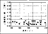
Fig. 1 is that the combustion case of acetate in transpiration-cooled LOR method of the present invention varies with temperature figure;
Fig. 2 is the side direction vertical cut-away schematic view of the LOR mixing tank of an embodiment of expression the present invention; With
Fig. 3 is the side direction vertical cut-away schematic view of popular response device structure, and this reactor can be used in oxo to come in the transpiration cooling operation of oxidizing hydrocarbons for air.
The objective of the invention is by with pure or transpiration-cooled using near pure oxygen Mode carries out that desired oxidation of organic compounds reacts to realize, particularly just makes easily Carry out this oxidation with the LOR method and system. For wherein some oxidation product or pair Product is in the reaction of solid phase, and the present invention has avoided using heat exchange surface to because in cooling Solids of sedimentation on the coil pipe heat transfer surface and the practical operation problem that causes. As a result, safety and have Utilize to effect pure oxygen or come the oxidation of organic compounds can be easily with evaporative cooling near pure oxygen Mode carry out, in order to desirably remove the reaction heat that during oxidation reaction, produces. This Working of an invention is so that described method and system can be anti-in condition and the oxidation of essentially no excess oxygen Answer the boiling point operation of mixture.
LOR method and system with this paper explanation and the improvement that claims are come oxidation of organic Compound can be strengthened the mass transport process of oxygen from gas phase to liquid phase greatly, thereby makes the general speed of reaction Ratio increases when using feeding air as oxygen source. The LOR system that adopts for the present invention has reduced gas Bubble is by the recirculation of drainage tube, and this is just desirable, because a large amount of consumption of oxygen led to first Cross the downward pumping that is positioned at reactor and rolling cited below district (roll cell) In screw impeller/drainage tube assembly. In order to make the present invention cost-effective, the consumption speed of oxygen The degree (that is, transfer to liquid phase and with the organic compound reaction of wanting oxidation) must be very high.
An important advantage of LOR method of the present invention is and since the gas liquid reaction mixture be from Drainage tube to be pumping at a high speed, carrying the jet of the peripheral liquid of drainage tube secretly and hits thereby form one Hit on the end of reactor, formed the rolling district in the bottom of reactor. These rolling districts are basic On captured the gas phase of disperseing, until it is become the bubble of cut off diameter by full consumption or aggegation, There is enough buoyancy to pass liquid rising and escape. The hydrodynamics of this pattern has produced very High coefficient of oxygen utilization.
In the LOR of improvement of the present invention system, carry out the process conditions one of oxidation of organic compounds As be industrial take air as the basis the scope that method was adopted in. The most obvious difference exists In, for reactant mixture and the operating temperature of appointment, the operating pressure of reactor take oxygen as To be lower than in the method on basis take the method for air as the basis.
But be noted that optimum process condition (for example for some special oxidizing process Operating temperature and catalyst concn) take oxygen as the basis reaction in can with accordingly with air Reaction difference for the basis. For typical oxidation reaction, take the warp of air as the method on basis The Ji benefit is the product selection during with the rising operating temperature to the benefit of reaction speed and conversion ratio by high temperature The property and the relative size of the loss of productive rate determine. Optionally this loss shows as the damage of solvent Lose increase and/or reactant and become useless accessory substance, for example carbon dioxide or carbon monoxide. Catalyst concn is to reaction speed and selectively similar impact can be arranged. Utilization resembles the present invention That adopts is this transpiration-cooled take the method for oxygen as the basis, product yield and reaction speed with Operating temperature raises and increases, but it is relevant with reaction temperature not observe solvent loss.
Referring to Fig. 1, in transpiration cooling of the present invention, be oxidized to terephthalic acid at p-Xylol as the solvent acid ignition quality of the function of temperature.Those skilled in the art can understand, and it is unfavorable that acetic acid solvent reacts, and find in type reaction temperature range (about 180 ℃-200 ℃) it with compare based on the method for air lower all the time.The data that marked are taken from improved 3.3 liters of LOR reactors according to the present invention.The internal diameter of this reactor is 5 inches, and the impeller of one 2 inches impeller and 3 inches is positioned at drainage tube and uses down at 1000 rev/mins, and this drainage tube is positioned at reactor described herein and that claim.Incoming mixture is 11% p-Xylol normally.Used catalysts is the acetate of cobalt and magnesium, and concentration range is respectively 200-2000ppm and 500-3000ppm.The bromine that uses the bromide form is as initiator, and its concentration in incoming mixture is 400-3000ppm.
Fig. 2 represents that a kind of mode of adopting the transpiration cooling reaction mixture according to the present invention of being applicable to is with pure oxygen or near the LOR system of the improvement of pure oxygen oxidation organic liquid.In this embodiment, organic liquid main body 2 and liquid-gas interface 3 and top gas phase 4 are housed in the reactor 1.Product liquid takes out in by reactor 1 through managing 5.The same with the LOR system of Litz etc., hollow drainage tube 6 is usually located at the central authorities of reactor 1, and opening 7 and 8 are respectively arranged at top and bottom.Impeller unit 9 is positioned at the drainage tube 6 of hollow.The screw impeller device that this impeller unit 9 is downward pumpings, be fit to promote liquid by the main body of liquid 2 in the hollow drainage tube 6 with flow downward at a high speed and promote turbulent flow rolling air chamber B form and the sidewall of reactor of the B top, district of rolling and hollow drainage tube 6 between liquid in the annular space upwards mobile.Impeller unit 9 generally includes radial-flow impellers device 10, if necessary, comprises that also under shield 11 realizes desired circulating to promote liquid in reactor 1.Link with suitable drive mechanism 13 so that impeller unit 9 runnings by reactor 1 upwardly extending suitable transmission shaft 12.
In Fig. 2 of the patent of Litz etc., can see that the ventilating chamber 29 of hollow preferably has a conical hopper shape part 30a in the top, flow into ventilating chamber as down going channel to promote the bubble liquid mixture.In the LOR of improvement of the present invention system, a conical hopper shape part is arranged equally in the upper end of hollow drainage tube 6, but its configuration and Litz's etc. is different fully, and it is to be used for opposite purpose, that is, reduce the number of bubbles that flows into hollow drainage tube 6 downwards.So the vertically extending conical hopper shape part 6a of hollow drainage tube 6 extends upward on the base section 6b of Cylinder normally, impeller unit then is positioned among the 6b.The increase of conical hopper shape part 6a top diameter plays a part to reduce liquid stream A and passes the speed that these hollow drainage tube 6 tops flow downward, and rises outside hollow drainage tube 6 in the reactor and is inhaled into that part of bubble in the impeller unit 9 with the reactant liquid stream of downward inflow hollow drainage tube 6 thereby reduced significantly.For this reason, the distance that the first half 6a of vertically extending conical hopper shape extends in vertical direction be equivalent to this hollow drainage tube lower part b length about 0% to about 200%, preferred about 100% to about 150%, lower part b is the Cylinder configuration of non-taper usually, and impeller unit 9 is positioned at wherein.The top diameter of this drainage tube (be upper part 6a top place enlarged diameter) size suitably is reduced to for example about 1.5 feet per seconds in certain embodiments so that liquid is passed the speed that drainage tube flows downward.The size of the first half 6a of drainage tube 6 can become with the total environment of specified purposes, but the gap between first half 6a and the reactor wall is general all in about 0.5-4 of drainage tube diameter scope doubly.In some cases, the enlarged diameter of first half 6a is 1.5 to 3.0 times of bottom 6b diameter.In specific embodiment, the enlarged diameter at the top of first half 6a is about 40%-80% of reactor inside diameter or width, preferably about 50%-60%.For specific purposes, the geometrical shape of impeller unit and rotating speed are the factors of the size of decision drainage tube 6 and first half 6a thereof.Through the high velocity liquid stream of the downward pumping of impeller unit, its speed generally arrives more than about 8 feet per seconds 5 or 6, so that form the district of rolling of high turbulence, captures undissolved oxygen and improves desired oxygen solubility.Among the above-mentioned conical hopper shape part 6a of hollow drainage tube 6, retaining device 6 ' are housed also preferably, to promote that liquid flows in the impeller unit 9 downwards.
Since charging oxygen when injecting hollow drainage tube 6 rapid consumption and pass the liquid that drainage tube top flows downward and reduce, the LOR impeller/drainage tube molectron of improvement of the present invention has reduced the quantity of the recycle gas that flows downward in the drainage tube effectively.The mobile bubble that makes progress outside lower part 6b of hollow drainage tube in reactor mainly comprises volatile organic compound (VOC), reactant solvents, water vapor and by product (as CO and CO
2), wherein only there is a small amount of undissolved oxygen, the evaporation of volatile organic matter provides to removing the required transpiration cooling effect of reaction heat of desired oxidation of organic compounds operation.As can be seen, in reactor 1, particularly near the top of upper part 6a of hollow drainage tube 6 and on drainage tube in the zone of liquid-vapo(u)r interface 3 bubble of rising only contain seldom oxygen, so the oxygen concn in the top gas phase 4 remains within the described limit easily to guarantee to eliminate the possibility of catching fire or exploding.Main body of liquid 2 near the zone of hollow drainage tube 6 upper part 6a and be higher than 6a that part ofly in fact constituted a relative immobilized zone that turbulent flow is less, similar to the LOR method and system formation of the patent of Litz etc.Should be understood that during oxidizing reaction gas emits from top gas phase 4 via discharge equipment 14.For the present invention, be also pointed out that, the non-funnel shaped part 6b in the bottom of hollow drainage tube 6 preferably is positioned at the Lower Half of reactor as shown in Figure 2, preferably, impact so that between the bottom surface of the bubble-liquid mixture of discharging and this reactor, form from the bottom of reactor 1 near the bottom of reactor.
Be the diverse gas flow pattern of narrating in the patent of promote to form implementing of the presently claimed invention and Litz etc. of solution-air married operation, in enforcement of the present invention, do not adopt to be used for bubble-liquid mixture is guided to the deflector device 34 corresponding retaining devices of hollow ventilating chamber 29 in the system with Litz etc.But the present invention adopts a kind of little horizontal baffle device, that is, garden dish 15, it be arranged in transmission shaft 12 on hollow drainage tube 6 impeller units around.This retaining device plays and prevents top gas phase 4 because the effect that the whirlpool effect is inhaled into along transmission shaft 12.
As mentioned above, the present invention's (particularly LOR method and system of its improvement) adopts pure or comes oxidation of organic compounds near pure oxygen, and uses vapor cooling system to remove the heat that oxidizing reaction produces.For this reason, strengthened oxygen greatly, so that total reaction rate is increased than the oxidizing reaction based on air by the mass transfer of gas phase in liquid phase.Enforcement of the present invention makes and might reach keto consumpting speed fast, thereby as described hereinly directly injecting pure oxygen for the first time or during near pure oxygen, just reach very high coefficient of oxygen utilization in hollow drainage tube 6, that is, at least 75%, preferred more than 90%.Such pure oxygen utilization ratio adds the configuration of above-mentioned hollow drainage tube 6, reduced the recirculation of bubble by drainage tube 6, thereby can advantageously utilize the transpiration cooling effect, and prevented that bad cavitation effect in the impeller unit 9, this cavitation effect from can stop or hinder the ideal cycle of liquid reactants and oxygen to burst apart and be dispersed into bubble rapidly in liquid reactants.
For evaporating and cooling method of the present invention, pure or add reactor 1 by the high turbulent flow position in the hollow drainage tube 6 or a little less than this position near pure oxygen feeding, rather than by other position of organic liquid body 2.Though can in the high turbulent area of above-mentioned hollow drainage tube 6, add oxygen in any position easily, for example directly send into the drainage tube lower part 6b that abuts against impeller unit 9 tops via injection tube 16, but the most desirable and most convenient is to implant oxygen into via injection tube 17 to be lower than screw impeller device 9 and radial-flow impellers device 10 among lower part 6b (if you are using, flat blade turbine for example) position perhaps is injected into the position between the screw impeller device 9 and radial impeller device 10 among lower part 6b (if with).Should know that these are high-shear positions.Be noted that injecting the oxygen charging is important at so high turbulent flow or high-shear position for the rapid consumption of desirable oxygen.The initial high density of oxygen plays a part to improve oxygen and enters mass transfer velocity in this regional liquid reactants in the decanting point place gas phase, otherwise the oxygen in the liquid phase can exhaust owing to oxidizing reaction speed fast.
When implementing Fig. 2 embodiment of the present invention, can feed nitrogen or other inert purge gas to top gas phase 4 via pipe 18, be lower than flammable limit safely to keep the oxygen concn in the top gas phase 14.Should be noted that in this respect, the configuration of drainage tube is a good pump, it has formed above-mentioned rolling air chamber, these air chambers capture undissolved oxygen, thereby can reach high oxygen efficiency, simultaneously compare and limited the quantity of needed nitrogen in the gas phase of top or other inert purge gas with following Fig. 3 embodiment.
Be noted that in less-than-ideal embodiment, replace air with oxygen and come oxidation of organic compounds (for example hydrocarbon) in the reactor of routine, to carry out, so that remove the oxidizing reaction liberated heat with vapor cooling system.In Fig. 3, reactor 20 comprises liquid reactants 21 bodies, liquid-vapo(u)r interface 22 and top gas phase 23, and oxygen injects wherein through managing 24.The whipping appts 25 that use is driven by transmission shaft 26 and CD-ROM drive motor 27 is dispersed into the form of the bubble 28 in liquid reactants 21 bodies with oxygen, and oxygen preferably is injected into the below of whipping appts 25.Nitrogen or other inertia discharging gas are incorporated in the top gas phase 23 via pipe 29, and discharging gas is then extracted out by pipe 30.
Boiling point in reaction mixture in reactor 20 carries out oxidizing reaction (promptly not having superfluous gaseous oxygen), and the reaction heat of oxidizing reaction is removed from reaction mixture by transpiration cooling.Under such condition, can realize using based on the viewed lot of advantages of the method for oxygen, that is, speed of response increases, and the exhaust jet stream amount reduces, and the formation of by product reduces.But, the safety problem that dangerous oxygen concn causes in the top gas phase 23 in the operation of this reactor must feed a large amount of nitrogen or other inertia discharging gas to prevent the safety problem that has generation owing to excess of oxygen in this gas phase in top gas phase 23.The ancillary cost of these nitrogen and other gas may be enough to make this embodiment to it seems that from the actually operating viewpoint becoming uneconomical calculates.Real economically feasible for the method that makes described embodiment, used here impeller must be dispersed into charging oxygen in very little bubble and make bubble that long mean residence time be arranged in liquid phase, so that realize the transfer of oxygen effectively.
Should be understood that, can make variations and modifications for details of the present invention as herein described and do not depart from the scope of claims.Method and system of the present invention is suitable for the exothermic oxidation of any organic compound.Because above-mentioned reason, desired product or by product were the oxidation of those organic compound of solid when the present invention was particularly suitable for oxidation.All many Alkylaromatics, for example p-Xylol all is to adopt transpiration cooling of the present invention to carry out the example of the particularly advantageous organic compound of oxidation.Except making terephthalic acid, any other dicarboxylic acid (for example m-phthalic acid), trimellitic acid and 2, the manufacturing of 6-naphthalene dicarboxylic acids all is the illustrative example that essential industry of the present invention is used.
By in the illustrated embodiment as seen, pure oxygen or oxygen rich gas are by directly being injected in the recycling part of fluid bulk near one or more notes oxygen points of impeller unit.For the present invention, the position of close impeller unit is the point in the field of turbulent flow that impeller unit produces, the suction that comprises impeller and discharging flow field.Should be pointed out that the district of rolling (that is, the rolling district B among Fig. 2) that forms below hollow drainage tube in the reactor lower part zone and the impeller unit, constituted the very part and parcel of the field of turbulent flow that produces by this impeller unit.
In implementing an illustrative embodiment of the present invention, produce terephthalic acid by the oxidation in Fig. 2 embodiment reactor 1 of the present invention of liquid p-Xylol.As solvent, use cobalt/Mn catalyst of 500-3000ppm with acetate, as initiator, bromine is 0.3: 1 with the ratio of catalyzer total amount with the bromine of hydrogen bromide form.Under the pressure of 115-180 pound/square inch, adopt about 200 ℃ temperature of reaction.Impeller unit 9 and radially the very high position of the shearing between the mixing tank 10 via pipe 17a pure basically oxygen is injected in the drainage tube.As a result, oxygen is very fast with the very form dispersion of small bubbles.Consume rapidly when therefore, oxygen is in transferring to liquid phase.Part reaction mixture evaporates under used reaction conditions, has removed reaction heat by the transpiration cooling effect.Because the position of the drainage tube shown in the figure and configuration are inhaled into the intravital trend of the liquid that flows downward again to the gas that rises and reduce to minimum at the top of hollow drainage tube 6 conical hopper shape first half 6a.Thereby reduce or avoided the possibility of cavitation effect greatly.Avoided equally, also not wishing that the reactant oxygen that takes place is diluted in drainage tube 6 Lower Halves.As a result, used oxygen is used effectively, and has successfully utilized the transpiration cooling effect, and compares with the prior art based on the manufacturing terephthalic acid of air, and the loss of solvent significantly reduces.
Preferably use pure basically oxygen in a preferred embodiment of the invention, but also can be with implementing the present invention near pure oxygen.For the present invention, this is the oxygen level oxygen-rich air more much higher than air near pure oxygen, for example oxygen level be at least 50%, preferably at least about 90% oxygen-rich air.
The present invention has made major progress in the oxidation of organic compounds field.The effective LOR of this height system can use under no cavitation effect through improvement ideally, makes this ideal LOR gas-liquid mixed method and system to use in transpiration-cooled mode.Enforcement of the present invention not only makes the LOR method and system expand to effectively and forms the oxidizing reaction of solid product or by product, and use pure in the embodiment of this invention or near pure oxygen make might adopt various reaction conditionss with the formation that reduces bad by product, reduce the solvent consumption in the reactive system and the generation of gas throughput and waste gas.Transpiration cooling characteristics of the present invention are providing unexpected significant benefit aspect the consumption that further reduces liquid reactants and solvent.All these benefits have all improved and carried out the technical of oxidation of organic compounds reaction and feasibility economically in various actual industrial operations.
Claims (18)
1. one kind is used for oxidation of organic compounds that the main body of liquid in the reactor is existed, and don't can make a large amount of oxygen be lost to method in the gas phase of top, and this method comprises:
(a) utilize the impeller that is arranged in the liquid phase main body to make the liquid phase main body keep the pattern that circulates, contain the organic compound for the treatment of oxidation that is present in the organic solvent in this liquid phase main body, liquid phase main body and top gas phase have a liquid-vapo(u)r interface;
(b) with pure oxygen or oxygen rich gas near impeller so that the one or more oxygen decanting points that are in the field of turbulent flow that produces by impeller directly be injected in the main body of liquid of recycling part, so that oxygen promptly is dispersed into small bubbles in liquid, very fast consumption when being convenient in being injected into liquid, transpiration cooling effect when volatile organic matter that the reaction heat that produces owing to the oxidation of organic compound is existed in the main body of liquid and water evaporation is removed, the organism of evaporation and bubble and only a spot of oxygen of water vapor rise in the aforesaid liquid main body together, pass a relative immobilized on reactor top, essentially no turbulent zone does not contain the mechanical refrigerating unit of direct contact in the reactor in rising to liquid-vapo(u)r interface and top gas phase; With
(c) emit the organism and the water vapor bubble of evaporation from the gas phase of top, make oxygen by this and treat that the organic compound of oxidation mixes under the condition that promotes the evaporation of rapid consumption of oxygen and organism and water, simultaneously minimum oxidation burble is in the gas phase of top.
2. also comprise in the gas phase of top and feed indifferent gas by the process of claim 1 wherein, so that the minor amounts of oxygen that flows in the gas phase of top is lost activity.
3. press the method for claim 1, wherein keep the recycled fluid flow problem in main body of liquid by an impeller that is arranged in the downward pumping of axial flow of reactor Lower Half, the decanting point of pure oxygen or oxygen rich air is in the field of turbulent flow that is produced by impeller, this impeller has a upwardly extending transmission shaft and position retaining device thereon, to prevent that gas is by being drawn in the liquid that flows through impeller along transmission shaft in the gas phase of top, the liquid that is downward through the impeller of described downward pumping flows downward with high speed, thereby produce the high turbulent district of rolling, it captures undissolved oxygen and has improved the solubleness of oxygen.
4. press the method for claim 3, wherein the impeller of axial flow, pumping downwards is positioned at a bottom of the hollow drainage tube of placing placed in the middle basically, this drainage tube respectively has opening so that liquid is circulated downwards at its top and bottom in the hollow drainage tube, then upwards flow in its outside, this hollow drainage tube has the conical hopper shape first half of an expansion, the vertical range that it extends downwards is about 0% to 200% of lower length, this upper part has the upper diameter of an expansion, and it has reduced liquid and has passed the speed that hollow drainage tube top flows downward.
5. by the method for claim 4, wherein the decanting point of oxygen be positioned at the axial flow of hollow drainage tube, downward pumping impeller below.
6. by the method for claim 5, wherein radial-flow impellers is positioned at the below of the impeller of the axial flow of hollow drainage tube, downward pumping, and the oxygen decanting point is between the impeller and radial-flow impellers of above-mentioned axial flow, pumping downwards.
7. by the method for claim 5, wherein radial-flow impellers is arranged in the below of the impeller of hollow drainage tube pumping downwards, and the decanting point of oxygen is below radial-flow impellers.
8. by the method for claim 4, wherein the decanting point of oxygen is below the hollow drainage tube.
9. by the method for claim 2, wherein main body of liquid remains on the boiling point of reaction mixture, and the gaseous oxygen of a small amount of surplus is wherein arranged.
10. by the method for claim 4, wherein the upwardly extending length of the conical hopper shape first half of the expansion of hollow drainage tube is about 100% to 150% of drainage tube Lower Half length.
11. one kind is used for the oxidation of organic compounds that will exist in main body of liquid and don't can makes a large amount of oxygen be lost to system in the gas phase of top, comprising:
(a) load onto the reactor of stating main body of liquid for one, contain the organic compound for the treatment of oxidation that exists in this liquid in organic solvent, main body of liquid and top gas phase have a liquid-vapo(u)r interface, do not contain the mechanical refrigerating unit of direct contact in the reactor;
(b) be used for keeping the impeller of liquid circulation flow model formula in the reactor;
(c) be used for pure oxygen or oxygen rich gas directly are injected into injection device in the main body of liquid, inject the close impeller in position so that be in the field of turbulent flow that produces by impeller, thereby oxygen promptly is dispersed into small bubbles in liquid so that very fast consumption in being injected into liquid the time, oxidation of organic compounds produce and reaction heat remove by the organism and the evaporation of water that exist in the main body of liquid, the organism that evaporates and the bubble of water vapour rise in main body of liquid with a spot of oxygen only, pass the essentially no turbulent of a relative immobilized zone in the reactor top, arrive liquid-vapo(u)r interface and top gas phase; With
(d) be used for from the gas phase of top, removing the discharge equipment of the bubble of the organism that evaporates and water vapor,
Can make oxygen and treat that the organic compound of oxidation mixes, and has only minimum oxygen bubbles to flow in the gas phase of top under the condition that promotes the evaporation of quick consumption of oxygen and organism and water with this system.
12. by the system of claim 11, comprising being used for indifferent gas is fed the conduit means of top gas phase.
13. system by claim 11, wherein impeller comprises that one is positioned at the axial flow of reactor, the impeller of pumping downwards, comprise that also a upwardly extending transmission shaft and position are used for thereon preventing that gas in the gas phase of top from crossing the retaining device in the liquid of impeller along this transmission shaft suction current, the impeller of pumping downwards can be with pumping liquid downwards at a high speed, thereby produces the turbulent flow that can capture undissolved oxygen and the improve oxygen solubility district of rolling.
14. system by claim 13, wherein also comprise a hollow drainage tube that is located substantially on central authorities, the impeller of axial flow, pumping downwards wherein is housed, this hollow drainage tube respectively has opening at its top and bottom, so that liquid is flowed downward in the hollow drainage tube, on the pipe extroversion, flow, this hollow drainage tube has the conical hopper shape first half of an expansion, its upwardly extending vertical range is about 0% to 200% of its Lower Half length, and this upper part has the upper diameter of an expansion to pass the downward flow velocity in hollow drainage tube top to reduce liquid.
15. by the system of claim 14, wherein the injection phase of oxygen is below the impeller of axial flow, pumping downwards in the hollow drainage tube.
16. by the system of claim 15, wherein also comprise the radial-flow impellers of the impeller below that is positioned at hollow drainage tube axial flow, pumping downwards, the oxygen injection phase is between the impeller and radial-flow impellers of axial flow, pumping downwards.
17. by the system of claim 15, wherein also comprise the radial-flow impellers of the impeller below that is positioned at the pumping downwards of hollow drainage tube, the oxygen injection phase is positioned at the below of radial-flow impellers.
18. by the system of claim 14, wherein the conical hopper shape first half of the expansion of hollow drainage tube extends upward about 100% to about 150% of Lower Half length.
Applications Claiming Priority (2)
| Application Number | Priority Date | Filing Date | Title |
|---|---|---|---|
| US24144494A | 1994-05-11 | 1994-05-11 | |
| US241,444 | 1994-05-11 |
Publications (2)
| Publication Number | Publication Date |
|---|---|
| CN1112910A CN1112910A (en) | 1995-12-06 |
| CN1064659C true CN1064659C (en) | 2001-04-18 |
Family
ID=22910728
Family Applications (1)
| Application Number | Title | Priority Date | Filing Date |
|---|---|---|---|
| CN95105721A Expired - Fee Related CN1064659C (en) | 1994-05-11 | 1995-05-10 | Enhanced oxidation of organic chemicals |
Country Status (11)
| Country | Link |
|---|---|
| US (1) | US5536875A (en) |
| EP (1) | EP0682000B1 (en) |
| JP (2) | JP3725202B2 (en) |
| KR (1) | KR100238501B1 (en) |
| CN (1) | CN1064659C (en) |
| BR (1) | BR9501991A (en) |
| CA (1) | CA2149058C (en) |
| DE (1) | DE69522365T2 (en) |
| ES (1) | ES2159584T3 (en) |
| PT (1) | PT682000E (en) |
| RU (1) | RU2140898C1 (en) |
Families Citing this family (60)
| Publication number | Priority date | Publication date | Assignee | Title |
|---|---|---|---|---|
| US5696285A (en) * | 1995-12-29 | 1997-12-09 | Praxair Technology, Inc. | Production of terephthalic acid with excellent optical properties through the use of pure or nearly pure oxygen as the oxidant in p-xylene oxidation |
| ID16017A (en) * | 1996-02-27 | 1997-08-28 | Praxair Technology Inc | PROCESS USED TO PRODUCE ORGANIC ACID |
| MX9702157A (en) * | 1996-03-22 | 1998-04-30 | Praxair Technology Inc | Optimization of water content in the oxygen-based oxidation of p-xylene. |
| ID19133A (en) * | 1996-12-12 | 1998-06-18 | Praxair Technology Inc | FILLING OXYGEN DIRECTLY INTO THE BULLET ROOM REACTORS |
| US7128278B2 (en) | 1997-10-24 | 2006-10-31 | Microdiffusion, Inc. | System and method for irritating with aerated water |
| US7654728B2 (en) | 1997-10-24 | 2010-02-02 | Revalesio Corporation | System and method for therapeutic application of dissolved oxygen |
| US6386751B1 (en) | 1997-10-24 | 2002-05-14 | Diffusion Dynamics, Inc. | Diffuser/emulsifier |
| US6702949B2 (en) | 1997-10-24 | 2004-03-09 | Microdiffusion, Inc. | Diffuser/emulsifier for aquaculture applications |
| US6362367B2 (en) | 1998-04-21 | 2002-03-26 | Union Carbide Chemicals & Plastics Technology Corp. | Preparation of organic acids |
| FR2791667B1 (en) * | 1999-03-30 | 2002-05-24 | Rhone Poulenc Fibres | PROCESS FOR THE OXIDATION OF HYDROCARBONS, ALCOHOLS AND / OR KETONES |
| FI109456B (en) * | 1999-08-12 | 2002-08-15 | Outokumpu Oy | Leaching of solid matter, e.g. metal concentrate, from sludge, uses reactor having double-action mixer in the vicinity of central pipe's lower edge |
| AU1935601A (en) * | 1999-12-10 | 2001-06-18 | Inca International S.P.A. | Impeller draft tube agitation system for gas-liquid mixing in a stirred tank reactor |
| DE10010771C1 (en) * | 2000-03-04 | 2001-05-03 | Celanese Chem Europe Gmbh | Production of aliphatic carboxylic acid, e.g. n-butyric, 2-methylbutyric, n-heptanoic or isononanoic acid, by oxidizing corresponding aldehyde uses group 5-11 metal or compound as catalyst |
| DE10049327A1 (en) * | 2000-10-05 | 2002-04-18 | Honeywell Specialty Chemicals | Method and device for producing nickel sulfamate |
| WO2002092549A1 (en) * | 2001-05-15 | 2002-11-21 | Inca International S.P.A. | Agitation system for alkylbenzene oxidation reactors |
| US6649773B2 (en) | 2002-03-22 | 2003-11-18 | General Electric Company | Method for the manufacture of halophthalic acids and anhydrides |
| US6657068B2 (en) | 2002-03-22 | 2003-12-02 | General Electric Company | Liquid phase oxidation of halogenated ortho-xylenes |
| US6657067B2 (en) | 2002-03-22 | 2003-12-02 | General Electric Company | Method for the manufacture of chlorophthalic anhydride |
| US7153480B2 (en) * | 2003-05-22 | 2006-12-26 | David Robert Bickham | Apparatus for and method of producing aromatic carboxylic acids |
| US7273950B2 (en) * | 2003-06-13 | 2007-09-25 | Tereftalatos Mexicanos, S.A. De C.V. | Process and apparatus for the efficient oxidation of alkyl aromatic compounds |
| CA2570936C (en) * | 2004-06-21 | 2011-08-16 | Blair H. Hills | Apparatus and method for diffused aeration |
| US7541489B2 (en) | 2004-06-30 | 2009-06-02 | Sabic Innovative Plastics Ip B.V. | Method of making halophthalic acids and halophthalic anhydrides |
| US20060205974A1 (en) * | 2005-03-08 | 2006-09-14 | Lavoie Gino G | Processes for producing aromatic dicarboxylic acids |
| US7550627B2 (en) * | 2005-03-08 | 2009-06-23 | Eastman Chemical Company | Processes for producing aromatic dicarboxylic acids |
| WO2007054323A1 (en) * | 2005-11-10 | 2007-05-18 | Vortex-Nanofluid Gmbh | Device comprising a spray device, and method for spraying nanodispersions |
| US8784897B2 (en) | 2006-10-25 | 2014-07-22 | Revalesio Corporation | Methods of therapeutic treatment of eyes |
| WO2008052145A2 (en) | 2006-10-25 | 2008-05-02 | Revalesio Corporation | Methods of therapeutic treatment of eyes and other human tissues using an oxygen-enriched solution |
| JP5306214B2 (en) | 2006-10-25 | 2013-10-02 | リバルシオ コーポレイション | Mixing equipment |
| US8784898B2 (en) | 2006-10-25 | 2014-07-22 | Revalesio Corporation | Methods of wound care and treatment |
| WO2008115290A2 (en) | 2006-10-25 | 2008-09-25 | Revalesio Corporation | Methods of wound care and treatment |
| US8445546B2 (en) | 2006-10-25 | 2013-05-21 | Revalesio Corporation | Electrokinetically-altered fluids comprising charge-stabilized gas-containing nanostructures |
| US8609148B2 (en) | 2006-10-25 | 2013-12-17 | Revalesio Corporation | Methods of therapeutic treatment of eyes |
| US7748891B2 (en) * | 2007-02-27 | 2010-07-06 | Chicago Bridge & Iron Company | Liquid storage tank with draft tube mixing system |
| US7722292B2 (en) | 2007-03-08 | 2010-05-25 | Golder Associates Ltd | Soil decontamination by mechanically activated oxidation |
| KR100734094B1 (en) | 2007-03-20 | 2007-06-29 | 도원환경기계(주) | Mixer |
| US9205388B2 (en) | 2007-06-27 | 2015-12-08 | H R D Corporation | High shear system and method for the production of acids |
| US8080685B2 (en) * | 2007-06-27 | 2011-12-20 | H R D Corporation | System and process for production of benzoic acids and phthalic acids |
| US9523090B2 (en) | 2007-10-25 | 2016-12-20 | Revalesio Corporation | Compositions and methods for treating inflammation |
| US10125359B2 (en) | 2007-10-25 | 2018-11-13 | Revalesio Corporation | Compositions and methods for treating inflammation |
| US9745567B2 (en) | 2008-04-28 | 2017-08-29 | Revalesio Corporation | Compositions and methods for treating multiple sclerosis |
| US8541623B2 (en) | 2011-01-04 | 2013-09-24 | Linde Aktiengesellschaft | Oxidation method and reactor |
| KR100988684B1 (en) | 2008-04-16 | 2010-10-18 | 삼남석유화학 주식회사 | Oxidation reactor for manufacturing of crude terephtalic acid |
| AU2009243045B2 (en) | 2008-05-01 | 2015-01-29 | Revalesio Corporation | Compositions and methods for treating digestive disorders |
| EP2140932A1 (en) * | 2008-07-04 | 2010-01-06 | Ammonia Casale S.A. | A process and a reactor for oxidation of a hydrocarbon |
| EP2406005A2 (en) * | 2009-03-13 | 2012-01-18 | University of Utah Research Foundation | Fluid-sparged helical channel reactor and associated methods |
| US8815292B2 (en) | 2009-04-27 | 2014-08-26 | Revalesio Corporation | Compositions and methods for treating insulin resistance and diabetes mellitus |
| IT1396221B1 (en) * | 2009-11-09 | 2012-11-16 | Polimeri Europa Spa | PROCEDURE FOR THE PREPARATION OF PHENOL FROM CUMENE. |
| BR112012028540A2 (en) | 2010-05-07 | 2016-07-26 | Revalesio Corp | compositions and methods for improving physiological performance and recovery time |
| DE102010023832A1 (en) * | 2010-06-10 | 2011-12-15 | Sig Technology Ag | Device and method for storing products |
| JP2013533320A (en) | 2010-08-12 | 2013-08-22 | レバレジオ コーポレイション | Compositions and methods for treating tauopathy |
| RU2604628C2 (en) * | 2012-09-17 | 2016-12-10 | НОВ КОНДОР ЭлЭлСи | Method and design of mixer |
| JP6521595B2 (en) * | 2014-09-10 | 2019-05-29 | ジヤトコ株式会社 | Liquid stirrer |
| CN109331746B (en) * | 2018-09-28 | 2021-11-19 | 大连理工大学 | Novel solid particle thermochemical reaction device and method |
| KR102212197B1 (en) * | 2018-11-05 | 2021-02-04 | 재단법인 포항산업과학연구원 | Kneader |
| CN111217671A (en) * | 2018-11-23 | 2020-06-02 | 南京延长反应技术研究院有限公司 | Methyl aromatic hydrocarbon oxidation reaction system and use method thereof |
| CN109718689B (en) * | 2019-01-25 | 2021-07-27 | 江苏师范大学 | Be used for mechanical rotation type bubble generator, environmental protection equipment |
| CN110917945B (en) * | 2019-12-12 | 2021-08-03 | 浙江科技学院 | Production is with upset reinforcing agitating unit |
| CN113070000B (en) * | 2021-04-08 | 2022-08-05 | 武汉理工大学 | Thermal cracking reaction method of self-adaptive reaction furnace with variable inner chamber shape |
| CN114653258A (en) * | 2022-05-06 | 2022-06-24 | 重庆医药高等专科学校 | A raw materials proportioning device for chemical production |
| CN115561058B (en) * | 2022-12-06 | 2023-03-03 | 坛墨质检科技股份有限公司 | Digestion device and digestion method for food metal content detection |
Citations (3)
| Publication number | Priority date | Publication date | Assignee | Title |
|---|---|---|---|---|
| US4722785A (en) * | 1977-11-04 | 1988-02-02 | Reid John H | Partial or non-barriered oxidation ditch having momentum conservation and increased oxygen transfer efficiency |
| EP0341813A1 (en) * | 1988-03-17 | 1989-11-15 | Amoco Corporation | Reactor and Process for the oxidation of alkyl aromatic compounds to aromatic carboxylic acids. |
| EP0439013A1 (en) * | 1990-01-04 | 1991-07-31 | Praxair Technology, Inc. | Enhanced gas-liquid reactions |
Family Cites Families (6)
| Publication number | Priority date | Publication date | Assignee | Title |
|---|---|---|---|---|
| US4900480A (en) * | 1986-10-21 | 1990-02-13 | Union Carbide Corporation | Gas-liquid mixing |
| JPS63178833A (en) * | 1986-10-21 | 1988-07-22 | ユニオン・カーバイド・コーポレーション | Method and apparatus for introducing gas into liquid |
| US4919849A (en) * | 1988-12-23 | 1990-04-24 | Union Carbide Industrial Gases Technology Corporation | Gas-liquid mixing process and apparatus |
| US5009816A (en) * | 1990-04-26 | 1991-04-23 | Union Carbide Industrial Gases Technology Corporation | Broad liquid level gas-liquid mixing operations |
| US5108662A (en) * | 1991-05-01 | 1992-04-28 | Union Carbide Industrial Gases Technology Corporation | Gas-liquid mixing process and apparatus |
| US5371283A (en) * | 1993-12-22 | 1994-12-06 | Praxair Technology, Inc. | Terephthalic acid production |
-
1995
- 1995-05-10 JP JP13576795A patent/JP3725202B2/en not_active Expired - Fee Related
- 1995-05-10 ES ES95107045T patent/ES2159584T3/en not_active Expired - Lifetime
- 1995-05-10 PT PT95107045T patent/PT682000E/en unknown
- 1995-05-10 DE DE69522365T patent/DE69522365T2/en not_active Expired - Fee Related
- 1995-05-10 RU RU95107151A patent/RU2140898C1/en not_active IP Right Cessation
- 1995-05-10 CN CN95105721A patent/CN1064659C/en not_active Expired - Fee Related
- 1995-05-10 CA CA002149058A patent/CA2149058C/en not_active Expired - Fee Related
- 1995-05-10 BR BR9501991A patent/BR9501991A/en not_active IP Right Cessation
- 1995-05-10 KR KR1019950011370A patent/KR100238501B1/en not_active IP Right Cessation
- 1995-05-10 EP EP95107045A patent/EP0682000B1/en not_active Expired - Lifetime
- 1995-05-22 US US08/447,327 patent/US5536875A/en not_active Expired - Lifetime
-
2005
- 2005-01-13 JP JP2005006411A patent/JP2005161313A/en not_active Withdrawn
Patent Citations (3)
| Publication number | Priority date | Publication date | Assignee | Title |
|---|---|---|---|---|
| US4722785A (en) * | 1977-11-04 | 1988-02-02 | Reid John H | Partial or non-barriered oxidation ditch having momentum conservation and increased oxygen transfer efficiency |
| EP0341813A1 (en) * | 1988-03-17 | 1989-11-15 | Amoco Corporation | Reactor and Process for the oxidation of alkyl aromatic compounds to aromatic carboxylic acids. |
| EP0439013A1 (en) * | 1990-01-04 | 1991-07-31 | Praxair Technology, Inc. | Enhanced gas-liquid reactions |
Also Published As
| Publication number | Publication date |
|---|---|
| US5536875A (en) | 1996-07-16 |
| RU2140898C1 (en) | 1999-11-10 |
| JP3725202B2 (en) | 2005-12-07 |
| PT682000E (en) | 2002-02-28 |
| BR9501991A (en) | 1996-02-27 |
| ES2159584T3 (en) | 2001-10-16 |
| JPH0859546A (en) | 1996-03-05 |
| EP0682000A1 (en) | 1995-11-15 |
| CA2149058C (en) | 1998-07-28 |
| RU95107151A (en) | 1997-02-10 |
| KR950031895A (en) | 1995-12-20 |
| EP0682000B1 (en) | 2001-08-29 |
| DE69522365D1 (en) | 2001-10-04 |
| KR100238501B1 (en) | 2000-01-15 |
| CN1112910A (en) | 1995-12-06 |
| CA2149058A1 (en) | 1995-11-12 |
| DE69522365T2 (en) | 2002-05-23 |
| JP2005161313A (en) | 2005-06-23 |
Similar Documents
| Publication | Publication Date | Title |
|---|---|---|
| CN1064659C (en) | Enhanced oxidation of organic chemicals | |
| JP3100309B2 (en) | Terephthalic acid production using evaporative cooling | |
| CN1078878C (en) | Production of terephthalic acid with excellent optical properties through use of pure or nearly pure oxygen as oxidant in P-xylene oxidation | |
| US4908471A (en) | Method for the production of benzene carboxylic acids and benzene dicarboxylic acid esters | |
| US6838061B1 (en) | Reactor for carrying out gas-liquid, liquid, liquid-liquid or gas-liquid-solid chemical reactions | |
| JP5015447B2 (en) | Improved method for chemical reactions related to cyanohydrins | |
| CN1253424C (en) | Process for production of aromatic carboxylic acids with improved water removal technique | |
| KR100327717B1 (en) | Improved reactor system | |
| WO1999054274A1 (en) | Preparation of organic acids | |
| JPH10330292A (en) | Direct oxygen injection to bubble column reactor | |
| KR20030068171A (en) | Low cost polyester process using a pipe reactor | |
| CN1109047A (en) | Terephthalic acid production | |
| JPH029839A (en) | Method and apparatus for manufacturing an aromatic carboxylic acid | |
| CN1031523A (en) | The treatment process that contains the method for quenching and the quench liquid of methylacrylic acid reactant gas | |
| MXPA00011275A (en) | Batch reactor with on-demand supply of reactive gas. | |
| JPH10316614A (en) | Production of aromatic polycarboxylic acid | |
| MXPA99006839A (en) | Best reactor system |
Legal Events
| Date | Code | Title | Description |
|---|---|---|---|
| C06 | Publication | ||
| PB01 | Publication | ||
| C10 | Entry into substantive examination | ||
| SE01 | Entry into force of request for substantive examination | ||
| C14 | Grant of patent or utility model | ||
| GR01 | Patent grant | ||
| C56 | Change in the name or address of the patentee |
Owner name: PLEX TECHNOLOGIES CORP. Free format text: FORMER NAME OR ADDRESS: PLACER TECHNOLOGY CO., LTD. |
|
| CP01 | Change in the name or title of a patent holder |
Patentee after: Praxair Technology, Inc. Patentee before: Praxair Technology Inc. |
|
| C19 | Lapse of patent right due to non-payment of the annual fee | ||
| CF01 | Termination of patent right due to non-payment of annual fee |