CN106464475B - Method, device and computer readable medium for transmitting beacon signal by channel - Google Patents
Method, device and computer readable medium for transmitting beacon signal by channel Download PDFInfo
- Publication number
- CN106464475B CN106464475B CN201580030587.3A CN201580030587A CN106464475B CN 106464475 B CN106464475 B CN 106464475B CN 201580030587 A CN201580030587 A CN 201580030587A CN 106464475 B CN106464475 B CN 106464475B
- Authority
- CN
- China
- Prior art keywords
- cubs
- transmission
- scheduled uplink
- uplink transmission
- radio frequency
- Prior art date
- Legal status (The legal status is an assumption and is not a legal conclusion. Google has not performed a legal analysis and makes no representation as to the accuracy of the status listed.)
- Active
Links
Images


Classifications
-
- H—ELECTRICITY
- H04—ELECTRIC COMMUNICATION TECHNIQUE
- H04W—WIRELESS COMMUNICATION NETWORKS
- H04W74/00—Wireless channel access, e.g. scheduled or random access
- H04W74/08—Non-scheduled or contention based access, e.g. random access, ALOHA, CSMA [Carrier Sense Multiple Access]
- H04W74/0808—Non-scheduled or contention based access, e.g. random access, ALOHA, CSMA [Carrier Sense Multiple Access] using carrier sensing, e.g. as in CSMA
-
- H—ELECTRICITY
- H04—ELECTRIC COMMUNICATION TECHNIQUE
- H04W—WIRELESS COMMUNICATION NETWORKS
- H04W16/00—Network planning, e.g. coverage or traffic planning tools; Network deployment, e.g. resource partitioning or cells structures
- H04W16/14—Spectrum sharing arrangements between different networks
-
- H—ELECTRICITY
- H04—ELECTRIC COMMUNICATION TECHNIQUE
- H04L—TRANSMISSION OF DIGITAL INFORMATION, e.g. TELEGRAPHIC COMMUNICATION
- H04L5/00—Arrangements affording multiple use of the transmission path
- H04L5/003—Arrangements for allocating sub-channels of the transmission path
- H04L5/0032—Distributed allocation, i.e. involving a plurality of allocating devices, each making partial allocation
-
- H—ELECTRICITY
- H04—ELECTRIC COMMUNICATION TECHNIQUE
- H04L—TRANSMISSION OF DIGITAL INFORMATION, e.g. TELEGRAPHIC COMMUNICATION
- H04L27/00—Modulated-carrier systems
- H04L27/0006—Assessment of spectral gaps suitable for allocating digitally modulated signals, e.g. for carrier allocation in cognitive radio
-
- H—ELECTRICITY
- H04—ELECTRIC COMMUNICATION TECHNIQUE
- H04L—TRANSMISSION OF DIGITAL INFORMATION, e.g. TELEGRAPHIC COMMUNICATION
- H04L5/00—Arrangements affording multiple use of the transmission path
- H04L5/003—Arrangements for allocating sub-channels of the transmission path
- H04L5/0048—Allocation of pilot signals, i.e. of signals known to the receiver
-
- H—ELECTRICITY
- H04—ELECTRIC COMMUNICATION TECHNIQUE
- H04L—TRANSMISSION OF DIGITAL INFORMATION, e.g. TELEGRAPHIC COMMUNICATION
- H04L5/00—Arrangements affording multiple use of the transmission path
- H04L5/003—Arrangements for allocating sub-channels of the transmission path
- H04L5/0053—Allocation of signaling, i.e. of overhead other than pilot signals
-
- H—ELECTRICITY
- H04—ELECTRIC COMMUNICATION TECHNIQUE
- H04W—WIRELESS COMMUNICATION NETWORKS
- H04W72/00—Local resource management
- H04W72/12—Wireless traffic scheduling
- H04W72/1263—Mapping of traffic onto schedule, e.g. scheduled allocation or multiplexing of flows
- H04W72/1268—Mapping of traffic onto schedule, e.g. scheduled allocation or multiplexing of flows of uplink data flows
-
- H—ELECTRICITY
- H04—ELECTRIC COMMUNICATION TECHNIQUE
- H04W—WIRELESS COMMUNICATION NETWORKS
- H04W72/00—Local resource management
- H04W72/20—Control channels or signalling for resource management
- H04W72/21—Control channels or signalling for resource management in the uplink direction of a wireless link, i.e. towards the network
-
- H—ELECTRICITY
- H04—ELECTRIC COMMUNICATION TECHNIQUE
- H04W—WIRELESS COMMUNICATION NETWORKS
- H04W74/00—Wireless channel access, e.g. scheduled or random access
- H04W74/08—Non-scheduled or contention based access, e.g. random access, ALOHA, CSMA [Carrier Sense Multiple Access]
- H04W74/0808—Non-scheduled or contention based access, e.g. random access, ALOHA, CSMA [Carrier Sense Multiple Access] using carrier sensing, e.g. as in CSMA
- H04W74/0816—Non-scheduled or contention based access, e.g. random access, ALOHA, CSMA [Carrier Sense Multiple Access] using carrier sensing, e.g. as in CSMA carrier sensing with collision avoidance
-
- H—ELECTRICITY
- H04—ELECTRIC COMMUNICATION TECHNIQUE
- H04L—TRANSMISSION OF DIGITAL INFORMATION, e.g. TELEGRAPHIC COMMUNICATION
- H04L27/00—Modulated-carrier systems
- H04L27/26—Systems using multi-frequency codes
- H04L27/2601—Multicarrier modulation systems
- H04L27/2602—Signal structure
-
- H—ELECTRICITY
- H04—ELECTRIC COMMUNICATION TECHNIQUE
- H04L—TRANSMISSION OF DIGITAL INFORMATION, e.g. TELEGRAPHIC COMMUNICATION
- H04L5/00—Arrangements affording multiple use of the transmission path
- H04L5/0001—Arrangements for dividing the transmission path
- H04L5/0003—Two-dimensional division
- H04L5/0005—Time-frequency
- H04L5/0007—Time-frequency the frequencies being orthogonal, e.g. OFDM(A), DMT
- H04L5/001—Time-frequency the frequencies being orthogonal, e.g. OFDM(A), DMT the frequencies being arranged in component carriers
-
- H—ELECTRICITY
- H04—ELECTRIC COMMUNICATION TECHNIQUE
- H04L—TRANSMISSION OF DIGITAL INFORMATION, e.g. TELEGRAPHIC COMMUNICATION
- H04L5/00—Arrangements affording multiple use of the transmission path
- H04L5/0001—Arrangements for dividing the transmission path
- H04L5/0014—Three-dimensional division
- H04L5/0023—Time-frequency-space
Abstract
Techniques for wireless communication are described. A method includes generating, at a wireless device, a Channel Usage Beacon Signal (CUBS), wherein a waveform of the CUBS is based at least in part on a scheduled uplink transmission by the wireless device; and transmitting, by the wireless device, the CUBS over the unlicensed radio frequency spectrum band to occupy the unlicensed radio frequency spectrum band prior to the scheduled uplink transmission.
Description
Cross-referencing
This patent application claims priority from U.S. patent application No.14/685,327 entitled "Channel use Beacon Signal transmission Based on Uplink Transmissions on the Unlicensed Radio Spectrum band" filed by Wei et al on 13/4/2015 and U.S. provisional patent application No.62/010,366 entitled "Channel use Beacon Signal transmission Based on Uplink Transmissions on the Unlicensed Radio Spectrum band" filed by Wei et al on 10/2014, and U.S. provisional patent application No.62/010,366 filed by Wei et al on 10/2014, entitled "Channel use Beacon Signal transmission Based on Uplink Transmissions on the Unlicensed Radio Spectrum band"; each of which is assigned to the assignee of the present application.
FIELD OF THE DISCLOSURE
The following relates generally to wireless communications, and more particularly to Channel Usage Beacon Signal (CUBS) transmissions based on uplink transmissions over an unlicensed radio frequency spectrum band.
Background
Wireless communication systems are widely deployed to provide various types of communication content such as voice, video, packet data, messaging, broadcast, and so on. These systems may be multiple-access systems capable of supporting communication with multiple users by sharing the available system resources (e.g., time, frequency, and power). Examples of such multiple-access systems include Code Division Multiple Access (CDMA) systems, Time Division Multiple Access (TDMA) systems, Frequency Division Multiple Access (FDMA) systems, and Orthogonal Frequency Division Multiple Access (OFDMA) systems.
As an example, a wireless multiple-access communication system may include several base stations, each supporting communication for multiple wireless devices (e.g., mobile phones and/or tablet computers) simultaneously. A base station may communicate with wireless devices on downlink channels (e.g., for transmissions from the base station to the wireless devices) and uplink channels (e.g., for transmissions from the wireless devices to the base station).
Some communication modes may enable communication with wireless devices over different radio frequency spectrum bands (e.g., licensed radio frequency spectrum bands and/or unlicensed radio frequency spectrum bands) of a cellular network. As data traffic in cellular networks using licensed radio frequency spectrum bands continues to increase, offloading at least some data traffic to unlicensed radio frequency spectrum bands may provide cellular operators with opportunities to enhance data transmission capacity. Prior to obtaining access to and communicating over the unlicensed radio frequency spectrum band, in some examples, a transmitting apparatus may perform a Listen Before Talk (LBT) procedure to contend for access to the unlicensed radio frequency spectrum band. The LBT procedure may include performing a Clear Channel Assessment (CCA) to determine whether a channel of the unlicensed radio frequency spectrum band is available. When it is determined that the channel of the unlicensed radio frequency spectrum band is not available (e.g., because another device is already using the channel of the unlicensed radio frequency spectrum band), a CCA may be performed on the channel again at a later time. Upon determining that a channel of the unlicensed radio frequency spectrum band is available or clear, a Channel Usage Beacon Signal (CUBS) or preamble may be transmitted on the channel to reserve the channel until a downlink transmission and/or an uplink transmission may be made on the channel.
SUMMARY
The present disclosure relates generally to one or more improved techniques for generating and transmitting a CUBS prior to an uplink transmission in an unlicensed radio frequency spectrum band. More specifically, the techniques rely on scheduled uplink transmissions by: e.g., matching the bandwidth of the CUBS with the bandwidth of the scheduled uplink transmission; matching a transmit power of the CUBS with a transmit power of the scheduled uplink transmission; and/or replicating a portion of the scheduled uplink transmission in a CUBS to generate the CUBS.
In a first set of illustrative examples, a method for wireless communication is described. In one example, the method may include: generating, at a wireless device, a Channel Usage Beacon Signal (CUBS), wherein a waveform of the CUBS is based at least in part on an uplink transmission scheduled by the wireless device; and transmitting, by the wireless device, the CUBS over the unlicensed radio frequency spectrum band to occupy the unlicensed radio frequency spectrum band prior to the scheduled uplink transmission.
In some examples of the method, generating the CUBS may include matching a transmit power of the CUBS to a transmit power of the scheduled uplink transmission. In some examples of the method, generating the CUBS may include matching a bandwidth of the CUBS to a bandwidth of the scheduled uplink transmission.
In some examples of the method, matching the bandwidth of the CUBS to the bandwidth of the scheduled uplink transmission may include matching the bandwidth of the CUBS to a set of tones allocated to the scheduled uplink transmission in some examples. In some examples, the method may include replicating at least a portion of the scheduled uplink transmission in a CUBS. In some examples, the method may include receiving, from a base station, an indication of a set of tones allocated to a scheduled uplink transmission. In some examples, the method may include determining a set of tones allocated to the scheduled uplink transmission based at least in part on a static or semi-static schedule associated with the scheduled uplink transmission.
In some examples of the method, matching the bandwidth of the CUBS to the bandwidth of the scheduled uplink transmission may include matching a number of resource block interlaces associated with the CUBS to a number of resource block interlaces associated with the scheduled uplink transmission. In some examples of the method, matching the bandwidth of the CUBS to the bandwidth of the scheduled uplink transmission may include matching a total number of resource blocks used to transmit the CUBS to a total number of resource blocks associated with the scheduled uplink transmission.
In some examples of the method, the scheduled uplink transmission may comprise a transmission selected from the group consisting of: physical Uplink Shared Channel (PUSCH) transmission, Physical Uplink Control Channel (PUCCH) transmission, and Sounding Reference Signal (SRS) transmission.
In some examples of the method, the scheduled uplink transmission may include both: SRS transmission and at least one of PUSCH transmission or PUCCH transmission. In these examples, the method may include: matching a bandwidth of the CUBS with a set of tones allocated to at least one of a PUSCH transmission or a PUCCH transmission; and transmitting the SRS transmission as a last symbol of the scheduled uplink transmission. In some of these examples, the method may further comprise: matching a total transmit power of the SRS transmissions to a total transmit power of at least one of the PUSCH transmissions or the PUCCH transmissions; and/or match a power spectral density of the SRS transmission to a power spectral density of at least one of the PUSCH transmission or the PUCCH transmission.
In some examples of the method, the scheduled uplink transmission may include a multiplexed transmission including an SRS transmission multiplexed with at least one of a PUSCH transmission or a PUCCH transmission. In these examples, the CUBS may transmit on the set of tones allocated to the multiplexed transmission.
In some examples of the method, the waveform of the CUBS may be further generated based at least in part on an identity of the wireless device. In some examples of the method, the waveform of the CUBS may be further generated based at least in part on an identity of a transmission period in which the scheduled uplink transmission is initially scheduled. In some examples of the method, the scheduled uplink transmission may be scheduled during a transmission period selected from the group consisting of: listen Before Talk (LBT) frames, base station synchronization frames, or subframes.
In some examples of the method, the wireless device may comprise a first wireless device, and the scheduled uplink transmission may comprise a first scheduled uplink transmission of a plurality of scheduled uplink transmissions transmitted to the base station during a transmission period. The plurality of scheduled uplink transmissions may also include a second scheduled uplink transmission of the second wireless device. The first scheduled uplink transmission may be different from the second scheduled uplink transmission.
In some examples of the method, the scheduled uplink transmission may comprise a first scheduled uplink transmission and the CUBS may comprise a first CUBS. In these examples, the method may further comprise: generating, at the wireless device, a second CUBS, wherein a waveform of the second CUBS may be based at least in part on a second scheduled uplink transmission of the wireless device; and transmitting, by the wireless device, the second CUBS over the unlicensed radio frequency spectrum band to occupy the unlicensed radio frequency spectrum band prior to the second scheduled uplink transmission.
In a second set of illustrative examples, an apparatus for wireless communication is described. In one configuration, the apparatus may include: means for generating a CUBS at a wireless device, wherein a waveform of the CUBS is based at least in part on an uplink transmission scheduled by the wireless device; and means for transmitting, by the wireless device, the CUBS over the unlicensed radio frequency spectrum band to occupy the unlicensed radio frequency spectrum band prior to the scheduled uplink transmission. In some examples, the apparatus may further include means for implementing one or more aspects of the method for wireless communication described above with respect to the first set of illustrative examples.
In a third set of illustrative examples, another apparatus for wireless communication is described. In one configuration, the apparatus may include a processor, a memory in electronic communication with the processor, and instructions stored in the memory. The instructions are executable by the processor to: generating, at a wireless device, a CUBS, wherein a waveform of the CUBS is based at least in part on an uplink transmission scheduled by the wireless device; and transmitting, by the wireless device, the CUBS over the unlicensed radio frequency spectrum band to occupy the unlicensed radio frequency spectrum band prior to the scheduled uplink transmission. In some examples, the instructions may also be executable by the processor to implement one or more aspects of the method for wireless communication described above with respect to the first set of illustrative examples.
In a fourth set of illustrative examples, a non-transitory computer-readable medium storing code for wireless communication is described. The code may include instructions executable by a processor to: generating, at a wireless device, a CUBS, wherein a waveform of the CUBS is based at least in part on an uplink transmission scheduled by the wireless device; and transmitting, by the wireless device, the CUBS over the unlicensed radio frequency spectrum band to occupy the unlicensed radio frequency spectrum band prior to the scheduled uplink transmission. In some examples, the instructions are also executable by the processor to cause the wireless communication apparatus to implement one or more aspects of the method for wireless communication described above with respect to the first set of illustrative examples.
The foregoing has outlined rather broadly the features and technical advantages of an example in accordance with the present disclosure in order that the detailed description that follows may be better understood. Additional features and advantages will be described hereinafter. The conception and specific examples disclosed may be readily utilized as a basis for modifying or designing other structures for carrying out the same purposes of the present disclosure. Such equivalent constructions do not depart from the spirit and scope of the appended claims. The features which are believed to be characteristic of the concepts disclosed herein, both as to their organization and method of operation, together with the associated advantages will be better understood from the following description when considered in connection with the accompanying figures. Each of the figures is provided for the purpose of illustration and description only and does not define the limits of the claims.
A further understanding of the nature and advantages of the present invention may be realized by reference to the following drawings. In the drawings, similar components or features may have the same reference numerals. Further, various components of the same type may be distinguished by following the reference label by a dash and a second label that distinguishes among the similar components. If only the first reference label is used in the specification, the description is applicable to any one of the similar components having the same first reference label irrespective of the second reference label.
Brief Description of Drawings
A further understanding of the nature and advantages of the present disclosure may be realized by reference to the following drawings. In the drawings, similar components or features may have the same reference numerals. Further, various components of the same type may be distinguished by following the reference label by a dash and a second label that distinguishes among the similar components. If only the first reference label is used in the specification, the description is applicable to any one of the similar components having the same first reference label irrespective of the second reference label.
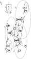
Fig. 1 illustrates a block diagram of a wireless communication system in accordance with various aspects of the present disclosure;
fig. 2 illustrates a wireless communication system in which LTE/LTE-a is deployed under different scenarios using an unlicensed radio frequency spectrum band, in accordance with aspects of the present disclosure;
fig. 3 illustrates an example of a gating interval (or LBT radio frame) for a cellular downlink in an unlicensed radio frequency spectrum band, in accordance with aspects of the present disclosure;
fig. 4 illustrates an example of wireless communication over an unlicensed radio frequency spectrum band, in accordance with various aspects of the present disclosure;
fig. 5 illustrates an example of wireless communication over an unlicensed radio frequency spectrum band, in accordance with various aspects of the present disclosure;
fig. 6 illustrates a message flow between a base station (e.g., a base station forming part or all of an eNB) and a wireless device in accordance with various aspects of the disclosure;
fig. 7 illustrates an example transmission of CUBS and PUSCH over an unlicensed radio frequency spectrum band, in accordance with various aspects of the present disclosure;
fig. 8 illustrates an example transmission of a CUBS and a PUCCH over an unlicensed radio frequency spectrum band, in accordance with various aspects of the present disclosure;
fig. 9 illustrates an example transmission of a CUBS and SRS over an unlicensed radio frequency spectrum band, in accordance with various aspects of the present disclosure;
fig. 10 illustrates a block diagram of an apparatus for use in wireless communications in accordance with various aspects of the disclosure;
fig. 11 illustrates a block diagram of an apparatus for use in wireless communications, in accordance with various aspects of the present disclosure;
fig. 12 shows a block diagram of a CUBS generation module, according to aspects of the present disclosure.
Fig. 13 illustrates a block diagram of a wireless device (e.g., a UE capable of communicating with one or more base stations) for use in wireless communications, in accordance with various aspects of the disclosure;
fig. 14 illustrates a block diagram of a base station (e.g., a base station forming part or all of an eNB) for use in wireless communications, in accordance with various aspects of the present disclosure;
fig. 15 is a flow diagram illustrating an example of a wireless communication method in accordance with various aspects of the present disclosure;
fig. 16 is a flow diagram illustrating an example of a wireless communication method in accordance with various aspects of the present disclosure; and
fig. 17 is a flow diagram illustrating an example of a method of wireless communication in accordance with various aspects of the present disclosure.
Detailed Description
Techniques are described in which CUBS transmissions are based on uplink transmissions over an unlicensed radio frequency spectrum band. As used in this description, a CUBS may be any signal that, in at least some aspects, serves as a preamble prior to data transmission. In some examples, the unlicensed radio frequency spectrum band may be used for cellular communications (e.g., Long Term Evolution (LTE) communications and/or LTE-advanced (LTE-a) communications). In some examples, the unlicensed radio frequency spectrum band may be a radio frequency spectrum band to which devices may need to contend for access because the radio frequency spectrum band is at least partially available for unlicensed use, such as Wi-Fi use.
With the increase of data traffic in cellular networks using licensed radio frequency spectrum bands, offloading at least some data traffic to unlicensed radio frequency spectrum bands may provide cellular operators (e.g., Public Land Mobile Networks (PLMNs) and/or operators defining a coordinated set of base stations of a cellular network, such as an LTE/LTE-a network) with opportunities for enhanced data transmission capacity. Prior to obtaining access to and communicating over the unlicensed radio frequency spectrum band, in some examples, a transmitting apparatus may perform an LBT procedure to obtain access to the unlicensed radio frequency spectrum band. Such LBT procedures may include performing a CCA (including, in some examples, an extended CCA) to determine whether a channel of an unlicensed radio frequency spectrum band is available. If it is determined that the channel is not available, a CCA may be performed again for the channel at a later time. Upon determining that a channel of the unlicensed radio frequency spectrum band is available or clear, a CUBS may be transmitted on the channel to reserve the channel until a downlink transmission and/or an uplink transmission may be made on the channel.
The disclosed techniques are based on scheduled uplink transmissions by: e.g., matching the bandwidth of the CUBS with the bandwidth of the scheduled uplink transmission; matching a transmit power of the CUBS with a transmit power of the scheduled uplink transmission; and/or replicating a portion of the scheduled uplink transmission in a CUBS to generate the CUBS.
The techniques described herein may be used for various wireless communication systems such as CDMA, TDMA, FDMA, OFDMA, SC-FDMA and other systems. The terms "system" and "network" are often used interchangeably. A CDMA system may implement a radio technology such as CDMA2000, Universal Terrestrial Radio Access (UTRA), and so on. CDMA2000 covers IS-2000, IS-95 and IS-856 standards. IS-2000 releases 0 and A are often referred to as CDMA 20001X, 1X, etc. IS-856(TIA-856) IS often referred to as CDMA 20001 xEV-DO, High Rate Packet Data (HRPD), etc. UTRA includes wideband CDMA (wcdma) and other CDMA variants. TDMA systems may implement radio technologies such as global system for mobile communications (GSM). OFDMA systems may implement methods such as Ultra Mobile Broadband (UMB), evolved UTRA (E-UTRA), IEEE 802.11(WiFi), IEEE 802.16(WiMAX), IEEE 802.20, Flash-OFDMTMAnd so on. UTRA and E-UTRA are Universal Mobile Telecommunications systems (UMT)S). 3GPP Long Term Evolution (LTE) and LTE-advanced (LTE-A) are new UMTS releases that use E-UTRA. UTRA, E-UTRA, UMTS, LTE-A, and GSM are described in literature from an organization named "third Generation partnership project" (3 GPP). CDMA2000 and UMB are described in documents from an organization named "third generation partnership project 2" (3GPP 2). The techniques described herein may be used for both the above-mentioned systems and radio technologies, as well as for other systems and radio technologies. However, the following description describes an LTE system for purposes of example, and LTE terminology is used in much of the description below, although the techniques may also be applied to applications other than LTE applications.
The following description provides examples and does not limit the scope, applicability, or examples set forth in the claims. Changes may be made in the function and arrangement of elements discussed without departing from the spirit and scope of the disclosure. Various examples may omit, substitute, or add various procedures or components as appropriate. For example, the described methods may be performed in an order different than described, and various steps may be added, omitted, or combined. Additionally, features described with reference to some examples may be combined in other examples.
Fig. 1 illustrates a block diagram of a wireless communication system 100 in accordance with various aspects of the disclosure. The wireless communication system 100 may include a plurality of base stations 105 (e.g., base stations forming part or all of one or more enbs), a number of wireless devices 115 (e.g., User Equipment (UE)), and a core network 130. Some base stations 105 may communicate with the wireless device 115 under the control of a base station controller (not shown), which may be part of the core network 130 or some of the base stations 105 in various examples. Some base stations 105 may communicate control information and/or user data with the core network 130 over a backhaul 132. In some examples, some of the base stations 105 may communicate with each other directly or indirectly through backhaul links 134, which backhaul links 134 may be wired or wireless communication links. The wireless communication system 100 may support operation on multiple carriers (waveform signals of different frequencies). A multi-carrier transmitter can transmit modulated signals on the multiple carriers simultaneously. For example, each communication link 125 may be a multi-carrier signal modulated according to various radio technologies. Each modulated signal may be transmitted on a different carrier and may carry control information (e.g., reference signals, control channels, etc.), overhead information, data, and so on.
The base station 105 may communicate wirelessly with the wireless device 115 via one or more base station antennas. Each base station 105 may provide communication coverage for a respective coverage area 110. In some examples, base station 105 may be referred to as an access point, a Base Transceiver Station (BTS), a radio base station, a radio transceiver, a Basic Service Set (BSS), an Extended Service Set (ESS), a node B, an evolved node B (eNB), a home node B, a home evolved node B, a Wireless Local Area Network (WLAN) access point, a WiFi node, or some other suitable terminology. The coverage area 110 of a base station 105 may be divided into sectors that form only a portion of the coverage area. The wireless communication system 100 may include different types of base stations 105 (e.g., macro, micro, and/or pico base stations). The base station 105 may also utilize different radio technologies, such as cellular and/or WLAN radio access technologies. The base stations 105 may be associated with the same or different access networks or operator deployments (e.g., collectively referred to herein as "operators"). The coverage areas of different base stations 105 (including coverage areas of base stations 105 of the same or different types, coverage areas utilizing the same or different radio technologies, and/or coverage areas belonging to the same or different access networks) may overlap.
In some examples, the wireless communication system 100 may include an LTE/LTE-a communication system (or network) that may support one or more operating or deployment modes of an unlicensed radio frequency spectrum band (e.g., a radio frequency spectrum band to which devices do not contend for access because the radio frequency spectrum band is licensed to particular users for particular uses, such as a licensed radio frequency spectrum band that may be used for LTE/LTE-a communications) and/or an unlicensed radio frequency spectrum band (e.g., a radio frequency spectrum band to which devices need to contend for access because the radio frequency band may be available for unlicensed uses, such as Wi-Fi uses). In other examples, the wireless communication system 100 may support wireless communication using one or more access technologies other than LTE/LTE-a. In an LTE/LTE-a communication system, the term evolved node B or eNB may be used, for example, to describe multiple or groups of base stations 105.
The wireless communication system 100 may be or include a heterogeneous LTE/LTE-a network in which different types of base stations 105 provide coverage for various geographic regions. For example, each base station 105 may provide communication coverage for a macrocell, picocell, femtocell, and/or other type of cell. Small cells, such as picocells, femtocells, and/or other types of cells, may include low power nodes or LPNs. A macro cell, for example, covers a relatively large geographic area (e.g., an area with a radius of several kilometers) and may allow unrestricted access by UEs with service subscriptions with the network provider. Picocells, for example, will cover a relatively small geographic area and may allow unrestricted access by UEs with service subscriptions with the network provider. A femtocell will also cover a relatively small geographic area (e.g., a home), for example, and may be provided with access, constrained in addition to unrestricted access, by UEs associated with the femtocell (e.g., UEs in a Closed Subscriber Group (CSG), UEs of users in the home, and the like). The eNB for a macro cell may be referred to as a macro eNB. An eNB for a picocell may be referred to as a pico eNB. Also, an eNB for a femtocell may be referred to as a femto eNB or a home eNB. An eNB may support one or more (e.g., two, three, four, etc.) cells.
The core network 130 may communicate with the base stations 105 via a backhaul 132 (e.g., S1 application protocol, etc.). The base stations 105 may also communicate with each other, e.g., directly or indirectly via backhaul links 134 (e.g., X2 application protocol, etc.) and/or via backhaul 132 (e.g., through core network 130). The wireless communication system 100 may support synchronous or asynchronous operation. For synchronous operation, each eNB may have similar frame and/or gating timing, and transmissions from different enbs may be approximately aligned in time. For asynchronous operation, each eNB may have different frame and/or gating timing, and transmissions from different enbs may not be aligned in time.
The wireless devices 115 may be dispersed throughout the wireless communication system 100. Wireless device 115 may also be referred to by those skilled in the art as a UE, a mobile device, a mobile station, a subscriber station, a mobile unit, a subscriber unit, a wireless unit, a remote unit, a wireless communication device, a remote device, a mobile subscriber station, an access terminal, a mobile terminal, a wireless terminal, a remote terminal, a handset, a user agent, a mobile client, a client, or some other suitable terminology. The wireless device 115 may be a cellular telephone, a Personal Digital Assistant (PDA), a wireless modem, a wireless communication device, a handheld device, a tablet computer, a laptop computer, a cordless telephone, a wearable item (such as a watch or glasses), a Wireless Local Loop (WLL) station, and so forth. Wireless device 115 may be capable of communicating with macro enbs, pico enbs, femto enbs, relays, and/or the like. The wireless device 115 may also be capable of communicating over different types of access networks, such as cellular or other WWAN access networks, or WLAN access networks. In some modes of communication with the wireless device 115, communication may be conducted over multiple communication links 125 or multiple channels (i.e., component carriers), where each channel uses a component carrier between the wireless device 115 and one of several cells (e.g., serving cells, which may be operated by the same or different base stations 105 in some cases).
Each component carrier may be provided over an licensed radio frequency spectrum band or an unlicensed radio frequency spectrum band, and the set of component carriers used in a particular communication mode may all be received over the licensed radio frequency spectrum band (e.g., at the wireless device 115), all be received over the unlicensed radio frequency spectrum band (e.g., at the wireless device 115), or a combination of the licensed radio frequency spectrum band and the unlicensed radio frequency spectrum band (e.g., at the wireless device 115).
The communication links 125 shown in the wireless communication system 100 may include uplink channels (using component carriers) for carrying Uplink (UL) communications (e.g., transmissions from the wireless device 115 to the base station 105) and/or downlink channels (using component carriers) for carrying Downlink (DL) communications (e.g., transmissions from the base station 105 to the wireless device 115). UL communications or transmissions may also be referred to as reverse link communications or transmissions, while DL communications or transmissions may also be referred to as forward link communications or transmissions. Downlink communications and/or uplink communications may be conducted using the licensed radio frequency spectrum band, the unlicensed radio frequency spectrum band, or both.
In some examples of the wireless communication system 100, LTE/LTE-a may be deployed in different scenarios using unlicensed radio frequency spectrum bands. The deployment scenario may include a supplemental downlink mode in which LTE/LTE-a downlink communications in the licensed radio frequency spectrum band may be offloaded to the unlicensed radio frequency spectrum band, a carrier aggregation mode in which both LTE/LTE-a downlink and uplink communications may be offloaded from the licensed radio frequency spectrum band to the unlicensed radio frequency spectrum band, and/or a standalone mode in which LTE/LTE-a downlink and uplink communications between the base station 105 and the wireless device 115 may be conducted in the unlicensed radio frequency spectrum band. In some examples, the base station 105 and the wireless device 115 may support one or more of these or similar modes of operation. OFDMA waveforms may be used in the communication link 125 for LTE/LTE-a downlink communications in the licensed radio frequency spectrum band and/or the unlicensed radio frequency spectrum band, while OFDMA, SC-FDMA and/or resource block interleaved FDMA waveforms may be used in the communication link 125 for LTE/LTE-a uplink communications in the licensed radio frequency spectrum band and/or the unlicensed radio frequency spectrum band.
Fig. 2 illustrates a wireless communication system 200 in which LTE/LTE-a is deployed under different scenarios using an unlicensed radio frequency spectrum band in accordance with various aspects of the present disclosure. More specifically, fig. 2 illustrates examples of a supplemental downlink mode, a carrier aggregation mode, and a standalone mode in which LTE/LTE-a is deployed using an unlicensed radio frequency spectrum band. The wireless communication system 200 may be an example of portions of the wireless communication system 100 described with reference to fig. 1. Further, the first base station 205 and the second base station 205-a may be examples of aspects of one or more of the base stations 105 described with reference to fig. 1, while the first wireless device 215, the second wireless device 215-a, the third wireless device 215-b, and the fourth wireless device 215-c may be examples of aspects of one or more of the wireless devices 115 described with reference to fig. 1.
In an example of a supplemental downlink mode in the wireless communication system 200, the first base station 205 may transmit an OFDMA waveform to the first wireless device 215 using the downlink channel 220. The downlink channel 220 may be associated with a frequency F1 in the unlicensed radio frequency spectrum band. The first base station 205 may transmit OFDMA waveforms to the first wireless device 215 using the first bidirectional link 225 and may receive SC-FDMA waveforms from the first wireless device 215 using the first bidirectional link 225. The first bidirectional link 225 may be associated with a frequency F4 in the licensed radio frequency spectrum band. The downlink channel 220 in the unlicensed radio frequency spectrum band and the first bidirectional link 225 in the licensed radio frequency spectrum band may operate concurrently. The downlink channel 220 may provide downlink capacity offload for the first base station 205. In some examples, the downlink channel 220 may be used for unicast services (e.g., addressed to one wireless device) or for multicast services (e.g., addressed to several wireless devices). This scenario may occur for any service provider, such as a Mobile Network Operator (MNO), that uses a licensed radio frequency spectrum and needs to alleviate certain traffic and/or signaling congestion.
In one example of a carrier aggregation mode in the wireless communication system 200, the first base station 205 may transmit an OFDMA waveform to the second wireless device 215-a using the second bidirectional link 230 and may receive the OFDMA waveform, an SC-FDMA waveform, and/or a resource block interleaved FDMA waveform from the second wireless device 215-a using the second bidirectional link 230. The second bidirectional link 230 may be associated with a frequency F1 in the unlicensed radio frequency spectrum band. The first base station 205 may also transmit OFDMA waveforms to the second wireless device 215-a using the third bidirectional link 235 and may receive SC-FDMA waveforms from the second wireless device 215-a using the third bidirectional link 235. The third bidirectional link 235 may be associated with a frequency F2 in the licensed radio frequency spectrum band. The second bidirectional link 230 may provide downlink and uplink capacity offloading for the first base station 205. Similar to the supplemental downlink described above, this scenario may occur with any service provider (e.g., MNO) that uses a licensed radio frequency spectrum band and needs to alleviate some traffic and/or signaling congestion.
In another example of a carrier aggregation mode in the wireless communication system 200, the first base station 205 may transmit an OFDMA waveform to the third wireless device 215-b using the fourth bidirectional link 240 and may receive the OFDMA waveform, an SC-FDMA waveform, and/or a resource block interleaved waveform from the third wireless device 215-b using the fourth bidirectional link 240. The fourth bidirectional link 240 may be associated with a frequency F3 in the unlicensed radio frequency spectrum band. The first base station 205 may also transmit an OFDMA waveform to the third wireless device 215-b using a fifth bidirectional link 245 and may receive an SC-FDMA waveform from the third wireless device 215-b using the fifth bidirectional link 245. The fifth bidirectional link 245 may be associated with a frequency F2 in the licensed radio frequency spectrum band. The fourth bidirectional link 240 may provide downlink and uplink capacity offload for the first base station 205. This example, as well as those provided above, are given for illustration purposes, and there may be other similar operating modes or deployment scenarios that combine LTE/LTE-a in licensed radio frequency spectrum band and unlicensed access radio frequency spectrum for capacity offloading.
As described above, one type of service provider that may benefit from capacity offloading provided by using LTE/LTE-a in unlicensed access radio frequency spectrum is a legacy MNO that has access to the LTE/LTE-a licensed radio frequency spectrum band. For these service providers, an example of operation may include a steering mode (e.g., supplemental downlink, carrier aggregation) using an LTE/LTE-a Primary Component Carrier (PCC) over a licensed radio frequency spectrum band and at least one Secondary Component Carrier (SCC) over an unlicensed radio frequency spectrum band.
In the carrier aggregation mode, data and control may be communicated, for example, in the licensed radio frequency spectrum band (e.g., via the first bidirectional link 225, the third bidirectional link 235, and the fifth bidirectional link 245), while data may be communicated, for example, in the unlicensed radio frequency spectrum band (e.g., via the second bidirectional link 230 and the fourth bidirectional link 240). The carrier aggregation mechanisms supported when using unlicensed access radio spectrum may fall into hybrid frequency division duplex-time division duplex (FDD-TDD) carrier aggregation or TDD-TDD carrier aggregation with different symmetries across component carriers.
In one example of a standalone mode in the wireless communication system 200, the second base station 205-a may transmit an OFDMA waveform to the fourth wireless device 215-c using the bidirectional link 250, and may receive the OFDMA waveform, an SC-FDMA waveform, and/or a resource block interleaved FDMA waveform from the fourth wireless device 215-c using the bidirectional link 250. The bidirectional link 250 may be associated with a frequency F3 in the unlicensed radio frequency spectrum band. The standalone mode may be used in non-legacy wireless access scenarios, such as intra-stadium access (e.g., unicast, multicast). Examples of service provider types for this mode of operation may be a stadium owner, a cable company, an event host, a hotel, an enterprise, or a large company that does not have access to licensed radio frequency spectrum bands.
In some examples, a transmitting apparatus (such as one of the base stations 105, 205, and/or 205-a described with reference to fig. 1 and/or 2 and/or one of the wireless devices 115, 215-a, 215-b, and/or 215-c described with reference to fig. 1 and/or 2) may use a gating interval to gain access to a channel of the unlicensed radio frequency spectrum band (e.g., a physical channel of the unlicensed radio frequency spectrum band). The gating interval may define an application to a contention-based protocol, such as an LBT protocol based at least in part on the LBT protocol specified in the European Telecommunications Standards Institute (ETSI) (EN 301893). When using a gating interval that defines the application of the LBT protocol, the gating interval may indicate when the transmitting apparatus needs to perform a contention procedure, such as a Clear Channel Assessment (CCA). The result of the CCA may indicate to the transmitting device whether a channel of the unlicensed radio frequency spectrum band is available or in use for the gating interval (also referred to as an LBT radio frame or a CCA frame). When the CCA indicates that the channel is available for a corresponding LBT radio frame (e.g., "clear" for use), the transmitting apparatus may reserve and/or use the channel of the unlicensed radio frequency spectrum band during part or all of the LBT radio frame. When the CCA indicates that the channel is not available (e.g., the channel is in use or reserved by another apparatus), the transmitting apparatus may be prevented from using the channel during the LBT radio frame.
In some cases, it may be useful for the transmitting device to generate the gating interval on a periodic basis and synchronize at least one boundary of the gating interval with at least one boundary of the periodic interval. For example, it may be useful to generate a periodic gating interval for a cellular downlink in an unlicensed radio frequency spectrum band and synchronize at least one boundary of the periodic gating interval with at least one boundary of a periodic interval associated with the cellular downlink (e.g., a periodic LTE/LTE-a radio interval). An example of such synchronization is shown in fig. 3.
Fig. 3 illustrates an example 300 of a gating interval (or LBT radio frame) for a cellular downlink in an unlicensed radio frequency spectrum band, in accordance with aspects of the present disclosure. The first gating interval 305, the second gating interval 315, and/or the third gating interval 325 may be used as a periodic gating interval by an eNB or wireless device that supports transmissions over an unlicensed radio frequency spectrum band. Examples of such enbs may include base stations 105, 205, and/or 205-a described with reference to fig. 1 and/or 2, and examples of such wireless devices may include wireless devices 115, 215-a, 215-b, and/or 215-c described with reference to fig. 1 and/or 2. In some examples, the first gating interval 305, the second gating interval 315, and/or the third gating interval 325 may be used with the wireless communication systems 100 and/or 200 described with reference to fig. 1 and/or 2.
As an example, the duration of the first gating interval 305 is shown as being equal to (or approximately equal to) the duration of the LTE/LTE-a radio frame 310 of the periodicity interval associated with the cellular downlink. In some examples, "about equal to" means that the duration of the first gating interval 305 is within a Cyclic Prefix (CP) duration of the periodic interval.
At least one boundary of the first gating interval 305 may be synchronized with at least one boundary of a periodic interval comprising LTE/LTE-a radio frames N-1 to N + 1. In some cases, the first gating interval 305 may have a boundary that aligns with a frame boundary of the periodic interval. In other cases, the first gating interval 305 may have a boundary that is synchronized with, but offset from, the frame boundary of the periodic interval. For example, the boundaries of the first gating interval 305 may be aligned with the subframe boundaries of the periodic interval or with the subframe midpoint boundaries of the periodic interval (e.g., the midpoint of a particular subframe).
In some cases, the periodic intervals may include LTE/LTE-A radio frames N-1 to N + 1. Each LTE/LTE-a radio frame 310 may have, for example, a 10 millisecond duration, while the first gating interval 305 may also have a 10 millisecond duration. In these cases, the boundary of the first gating interval 305 may be synchronized with a boundary (e.g., a frame boundary, a subframe boundary, or a subframe midpoint boundary) of one of the LTE/LTE-a radio frames (e.g., LTE/LTE-a radio frame (N)).
As an example, the durations of the second gating interval 315 and the third gating interval 325 are shown as a submultiple (or approximate submultiple) of the duration of the periodic interval associated with the cellular downlink. In some examples, "approximately submultiple" means that the duration of the second gating interval 315 and/or the third gating interval 325 is within a Cyclic Prefix (CP) duration of a submultiple (e.g., one-half or one-fifth) of the duration of the periodic interval. For example, the second gating interval 315 may have a duration of 5 milliseconds, while the third gating interval 325 may have a duration of two milliseconds. The second gating interval 315 or the third gating interval 325 may be preferred over the first gating interval 305 because their shorter duration may facilitate more frequent sharing of the unlicensed radio frequency spectrum band.
Fig. 4 illustrates an example 400 of wireless communications 410 over an unlicensed radio frequency spectrum band in accordance with various aspects of the present disclosure. An LBT radio frame 415, which may correspond to a gating interval (such as the first gating interval 305 described with reference to fig. 3), may have a duration of 10 milliseconds and include a number of downlink subframes 420, a number of uplink subframes 425, and two types of special subframes (S subframes 430 and S' subframes 435). The S subframe 430 may provide a transition between the downlink subframe 420 and the uplink subframe 425, while the S' subframe 535 may provide a transition between the uplink subframe 425 and the downlink subframe 420. During the S' subframe 435, a Downlink Clear Channel Assessment (DCCA) procedure 440 may be performed by one or more base stations (such as one or more of the base stations 105, 205, and/or 205-a described with reference to fig. 1 and/or 2) to reserve a channel over which the wireless communication 410 occurs for a period of time. After a successful DCCA 440 is performed by a base station, the base station may transmit a Channel Usage Beacon Signal (CUBS)445 to provide an indication to other base stations and/or devices (e.g., wireless devices, Wi-Fi access points, etc.) that the base station has reserved the channel. The CUBS 445 may reserve this channel for transmission not only by the base station, but also for uplink transmission by its UEs. The CUBS 445 may also provide signals for Automatic Gain Control (AGC) and tracking loop updates for the wireless device before the base station transmits data to the wireless device. In some examples, the CUBS 445 may be transmitted using multiple interleaved resource blocks. Transmitting the CUBS 445 in this manner may enable the CUBS 445 to occupy at least a particular percentage of the available frequency bandwidth in the unlicensed radio frequency spectrum band and satisfy one or more regulatory requirements (e.g., a requirement that the CUBS 445 occupy at least 80% of the available frequency bandwidth). In some examples, the CUBS 445 may take forms similar to LTE/LTE-a cell-specific reference signals (CRSs), LTE/LTE-a preambles, and/or channel state information reference signals (CSI-RSs). The CUBS 445 is not transmitted when the DCCA 440 fails.
The S' subframe 435 may include 14 OFDM symbols, numbered 0 through 13 in fig. 4. The first portion of the S' subframe 435 (symbols 0 through 5 in this example) may be used by the base station as a silent DL period, which may be required for compatibility with the LTE/LTE-a communication standard. Thus, the base station may not transmit data during the silent DL period, but the wireless device may transmit a certain amount of uplink data during the silent DL period. The second portion of the S' subframe 435 may be used for DCCA 440. In the example 400, the S' subframe 435 includes 7 DCCA slots, which are included in symbols 6 through 12. The use of DCCA timeslots by different network operators may be coordinated to provide more efficient system operation. In some examples, to determine which of the 7 possible DCCA slots to use to perform DCCA 440, the base station 105 may evaluate a mapping function of the form:
FU(GroupID,t)∈{1,2,3,4,5,6,7}
where GroupID (group ID) is the "deployment group ID" assigned to the base station 105, and t is the LBT radio frame number corresponding to the gating interval or frame for performing the DCCA 440.
Fig. 5 illustrates an example 500 of wireless communications 510 over an unlicensed radio frequency spectrum band in accordance with various aspects of the present disclosure. LBT radio frame 515, which may correspond to a gating interval (such as first gating interval 305 described with reference to fig. 3) and/or LBT radio frame 415 described with reference to fig. 4, may have a duration of 10 milliseconds and include a number of downlink subframes 520, a number of uplink subframes 525, and two types of special subframes (e.g., S subframes 530 and S' subframes 535). The S subframe 530 may provide a transition between the downlink subframe 520 and the uplink subframe 525, while the S' subframe 535 may provide a transition between the uplink subframe 525 and the downlink subframe 520. During the S subframe 530, an uplink cca (ucca) procedure 540 may be performed by one or more wireless devices, such as one or more of the wireless devices 115, 215-a, 215-b, and/or 215-c described with reference to fig. 1 and/or 2, to reserve a channel on which the wireless communication 510 occurs for a period of time. After successful UCCA 540 is performed by the wireless device, the wireless device may transmit CUBS 545 to provide an indication to other wireless devices and/or apparatuses (e.g., base stations, Wi-Fi access points, etc.) that the wireless device has reserved the channel. In some examples, the CUBS 545 may be transmitted using multiple interleaved resource blocks. Transmitting the CUBS 545 in this manner may enable the CUBS 545 to occupy at least a certain percentage of the available frequency bandwidth in the unlicensed radio frequency spectrum band and meet one or more regulatory requirements (e.g., a requirement that the CUBS 545 occupy at least 80% of the available frequency bandwidth). In some examples, the CUBS 545 may take a form similar to LTE/LTE-a cell-specific reference signals (CRS) and/or channel state information reference signals (CSI-RS). Upon UCCA 540 failure, CUBS 545 is not transmitted.
The S subframe 530 may include 14 OFDM symbols, numbered 0 through 13 in fig. 5. A first portion of the S subframe 530 (symbols 0 through 3 in this example) may be used as a downlink pilot time slot (DwPTS)550, and a second portion of the S subframe 530 may be used as a Guard Period (GP) 555. A third portion of S subframe 530 may be used for UCCA 540. In example 500, S subframe 530 includes 7 UCCA slots, which are included in symbols 6 through 12. The use of UCCA slots by different wireless devices may be coordinated to provide more efficient system operation. In some examples, to determine which of the 7 possible UCCA slots to use to perform UCCA 540, the wireless device may evaluate a mapping function of the form:
FU(GroupID,t)∈{1,2,3,4,5,6,7}
where GroupID is the "deployment group id" assigned to the wireless device, and t is the LBT radio frame number corresponding to the frame for which UCCA 540 is performed.
The mapping function for DCCA 440 and/or UCCA 540 may be constructed based at least in part on different criteria, depending on whether the mapping function will have orthogonal or non-orthogonal properties. In examples with orthogonal LBT access, the mapping function may have orthogonal properties according to:
FD/U(x,t)≠FD/U(y,t)
GroupID x,y∈{1,2,3,4,5,6,7}
for all times t, every time x ≠ y denotes a different group id. In this case, base stations and/or wireless devices with different group ids may perform CCA (e.g., DCCA 440 and/or UCCA 540) during non-overlapping CCA slots. Without interference, a base station or wireless device with a group id mapped to an earlier CCA slot may protect the channel for a period of time. According to various deployments, at mapping { FD/UThe mapping function is fair in the sense that (x, t), t 1, 2, 3. } varies across different time indices t such that different group ids have equal probability of mapping to earlier CCA slots over a reasonably long time interval (and thus protect the channel in the absence of other interference).
All base stations and wireless devices deployed by the same network operator/service provider may be assigned the same group-id so that they do not preempt each other in the contention process. This allows full frequency reuse between identically deployed base stations and wireless devices, resulting in enhanced system throughput. Different deployed base stations and/or wireless devices may be assigned different group ids such that access to the channel is mutually exclusive with orthogonal CCA slot mapping.
In the example of non-orthogonal or overlapping CCA slot access, the mapping function may allow more than seven group ids. For example, in some cases it may be useful to support more than 7 deployment group-ids, in which case it is not possible to maintain the orthogonal nature of the CCA slot mapping function. In such a scenario, it may be desirable to reduce the frequency of collisions between any two cluster ids. In some examples, non-orthogonal CCA slot mapping sequences may also be used to provide fair channel access between deployments without tight coordination of LBT opportunities. An example of a non-orthogonal CCA slot mapping sequence is given by:
FD/U(x,t)=R1,7(x,t)
GroupID x=∈{1,2,...216}
wherein R is1,7(x, t) is a pseudo-random number generator chosen independently for GroupIDx between 1 and 7. In this case, there may be potential collisions between base stations and/or wireless devices of different group IDs in the same LBT radio frame t.
Thus, CCA slots may be selected according to the mentioned mapping function and used for DCCA 440 and/or UCCA 540.
In some examples, power control may be provided for downlink transmissions and/or uplink transmissions of a wireless communication system. In some examples, power control may be provided for transmissions over an unlicensed radio frequency spectrum band. For power control of LTE/LTE-a downlink transmissions, including LTE/LTE-a downlink transmissions over the unlicensed radio frequency spectrum band, the total transmission power of the downlink transmissions of the cell may be broadcast in system information block one (SIB 1). This may help the wireless device perform path loss measurements. In some examples, Common Reference Signals (CRS) in downlink transmissions may be power boosted. Although power control for control/data downlink transmissions may be largely unspecified and left to be implemented, there may be certain practical limitations to power control for control/data downlink transmissions. For example, the power boost for control/data downlink transmissions may be limited to not exceed a threshold (e.g., 6 dB). In some examples, the traffic-to-pilot power ratio (TPR) is fixed for high modulation orders (16 quadrature amplitude modulation (16QAM) and above) of CRS-based Physical Downlink Shared Channel (PDSCH). The TPR may also be fixed for the PDSCH based on the demodulation reference signal (DM-RS).
For power control of LTE/LTE-a uplink transmissions (including LTE/LTE-a uplink transmissions over the unlicensed radio frequency spectrum band), both open-loop and closed-loop power control may be supported. In some examples, an accumulated power control mode and/or an absolute power control mode may be supported for Physical Uplink Shared Channel (PUSCH) power control and/or Sounding Reference Signal (SRS) power control. The wireless device may be related at a higher layer to which power control mode (cumulative and/or absolute) the wireless device is to use for PUSCH power control and/or SRS power control configuration. In some examples, a configurable power offset may be provided between SRS power control and PUSCH power control. A bandwidth difference between SRS power control and PUSCH power control may also be provided. In some examples, only the accumulated power mode may be supported for Physical Uplink Control Channel (PUCCH) power control.
In LTE/LTE-a networks, power control for downlink transmissions and/or uplink transmissions may be provided on a per-subframe basis.
Fig. 6 illustrates a message flow 600 between a base station 605 (e.g., a base station forming part or all of an eNB) and a wireless device 615 in accordance with various aspects of the disclosure. In some examples, the base station 605 may be an example of aspects of one or more of the base stations 105, 205, and/or 205-a described with reference to fig. 1 and/or 2, and the wireless device 615 may be an example of aspects of one or more of the wireless devices 115, 215-a, 215-b, and/or 215-c described with reference to fig. 1 and/or 2. In some examples, the base station 605 and the wireless device 615 may be configured to communicate in a supplemental downlink mode, a carrier aggregation mode, and/or an independent mode over an unlicensed radio frequency spectrum band (e.g., a radio frequency spectrum band to which apparatuses may need to contend for access due to the radio frequency spectrum band being available for, at least in part, unlicensed use, such as Wi-Fi use).
In some examples, the message flow 600 may begin with transmitting scheduling information 620 from the base station 605 to the wireless device 615 for uplink transmission by the wireless device 615. In some examples, the received scheduling information 620 may include an indication of a set of tones allocated to the scheduled uplink transmission. In some examples, tone sets may be indicated in terms of resource blocks or resource block interlaces. A resource block interlace may include multiple resource blocks separated by other resource blocks in the frequency domain. In some examples, scheduling information 620 for uplink transmissions may also or alternatively be received from a base station other than base station 605. In some examples, scheduling information 620 for uplink transmissions may be based at least in part on static or semi-static scheduling, and may be used to schedule more than one uplink transmission. In some examples, the scheduling information 620 may be transmitted over an unlicensed radio frequency spectrum band. In some examples, the scheduling information 620 may be transmitted over a licensed radio frequency spectrum band.
At block 625, the wireless device 615 may contend for access to the unlicensed radio frequency spectrum band. Contending for access to the unlicensed radio frequency spectrum band may include performing UCCA. At block 630, the wireless device 615 may determine whether UCCA was successful (e.g., the wireless device 615 may determine whether the unlicensed radio frequency spectrum band or its channel is clear for access).
Upon successful contention for access to the unlicensed radio frequency spectrum band by the wireless device 615, the wireless device 615 may generate a CUBS at block 635. The waveform of the CUBS may be based at least in part on the scheduled uplink transmission 645 of the wireless device 615. In some examples, the scheduled uplink transmission on which the CUBS is based may include a PUSCH transmission, a PUCCH transmission, and/or an SRS transmission. In some examples, the scheduled uplink transmission on which the CUBS is based may include an SRS transmission multiplexed with at least one of a PUSCH transmission or a PUCCH transmission.
In some examples, the waveform of the CUBS generated at block 635 may also or alternatively be generated based at least in part on an identity of the wireless device 615 and/or an identity of a transmission period in which the scheduled uplink transmission was originally scheduled. In some examples, the transmission period in which the scheduled uplink transmission is initially scheduled may be an LBT frame, a base station synchronization frame, or a subframe, and the identity of the transmission period in which the scheduled uplink transmission is initially scheduled may be a current or previous LBT frame, a base station synchronization frame, or a subframe. The identified transmission period may be, for example, a previous transmission period when the wireless device was unable to successfully contend for access to the unlicensed radio frequency spectrum band for the transmission period in which the scheduled uplink transmission was originally scheduled.
In some examples, generating the CUBS may include matching a bandwidth of the CUBS to a bandwidth of the scheduled uplink transmission 645. In some examples, matching the bandwidth of the CUBS to the bandwidth of the scheduled uplink transmission 645 may include matching the bandwidth of the CUBS to a set of tones allocated to the scheduled uplink transmission 645. In some examples, matching the bandwidth of the CUBS to the bandwidth of the scheduled uplink transmission 645 may include matching a number of resource block interlaces associated with the CUBS to a number of resource block interlaces associated with the scheduled uplink transmission 645. In some examples, matching the bandwidth of the CUBS to the bandwidth of the scheduled uplink transmission 645 may include matching a total number of resource blocks used to transmit the CUBS to a total number of resource blocks associated with the scheduled uplink transmission 645.
In some examples, generating the CUBS may include matching a transmit power of the CUBS to a transmit power of the scheduled uplink transmission 645.
In some examples, generating the CUBS may include replicating at least a portion of the scheduled uplink transmission 645 (e.g., at least a portion of a payload of the scheduled uplink transmission 645) in the CUBS.
At block 640, the wireless device 615 may transmit a CUBS over the unlicensed radio frequency spectrum band to occupy the unlicensed radio frequency spectrum band prior to the scheduled uplink transmission 645.
In some examples, the wireless device 615 may comprise a first wireless device, and the scheduled uplink transmission may comprise a first scheduled uplink transmission of a plurality of scheduled uplink transmissions transmitted to the base station 605 during a transmission period. The plurality of scheduled uplink transmissions may also include a second scheduled uplink transmission of the second wireless device. In these examples, the first scheduled uplink transmission may be different from the second scheduled uplink transmission, and thus the first CUBS may be different from a second CUBS transmitted over the unlicensed radio frequency spectrum band prior to the second scheduled uplink transmission for occupying the unlicensed radio frequency spectrum band.
In some examples, the scheduled uplink transmission may comprise a first scheduled uplink transmission and the CUBS may comprise a first CUBS. In these examples, the wireless device 615 may further generate a second CUBS. The waveform of the second CUBS may be based at least in part on a second scheduled uplink transmission of the wireless device 615. The wireless device 615 may transmit a second CUBS over the unlicensed radio frequency spectrum band to occupy the unlicensed radio frequency spectrum band prior to the second scheduled uplink transmission.
As an example, the message flow 600 ends with the wireless device 615 transmitting the scheduled uplink transmission 645.
When the wireless device is not successfully contending for access to the unlicensed radio frequency spectrum band, the operations at blocks 635 and 640 may not be performed and the scheduled uplink transmission 645 may not be made. Alternatively, the CUBS may be generated at block 635, but may not be transmitted at block 640, and the scheduled uplink transmission 645 may not be made.
In some examples, base station 605 may provide scheduling information to a plurality of wireless devices, such as wireless device 615. In such an example, the base station 605 can monitor the CUBS from each of the plurality of wireless devices to determine which of the wireless devices successfully contend for access to the unlicensed radio frequency spectrum band. Because different ones of the wireless devices may successfully contend for access to the unlicensed radio frequency spectrum band at different times and sometimes in different LBT radio frames, the base station 605 may monitor the CUBS during the extended period of time. In some examples, the wireless device may indicate in the CUBS whether a subsequent uplink transmission is scheduled to be transmitted during a previous frame or a current frame.
In general, CUBS may be transmitted by a wireless device, such as wireless device 615, to contend for access to the unlicensed radio frequency spectrum band during LBT radio frames, base station (or eNB) synchronization frames, and/or subframes, and thus may be generated as a function of the LBT radio frames, base station (or eNB) synchronization frames, and/or subframes.
Turning now to scheduled uplink transmissions including PUCCH transmissions and/or PUSCH transmissions, conventional LTE/LTE-a PUCCH transmissions and/or PUSCH transmissions may occupy only one resource block in the frequency domain (e.g., occupy only a small subset of contiguous tones within the radio frequency spectrum band). However, there may be a requirement for certain communications in the unlicensed radio frequency spectrum band (e.g., LTE/LTE-a communications in the unlicensed radio frequency spectrum band) to occupy at least a particular percentage of the available frequency bandwidth in the unlicensed radio frequency spectrum band (e.g., at least 80% of the available frequency bandwidth). To meet such requirements, in some examples, PUCCH transmissions and/or PUSCH transmissions may be transmitted on one or more resource block interlaces in the frequency domain, where a resource block interlace includes multiple resource blocks. In some examples, the unlicensed radio frequency spectrum band may be divided into ten resource block interlaces, where each resource block interlace includes ten resource blocks. With such a configuration of resource blocks and resource block interlaces, in some examples, PUCCH transmissions and/or PUSCH transmissions may be scheduled on one or more of the resource block interlaces (e.g., a set of one or more ten spaced apart resource blocks).
Fig. 7 illustrates an example transmission 700 of a CUBS 720 and a PUSCH transmission 705 over an unlicensed radio frequency spectrum band, in accordance with various aspects of the present disclosure. As an example, fig. 7 may show only a subset of resource blocks 710 in the unlicensed radio frequency spectrum band. In some examples, the unlicensed radio frequency spectrum band may include one hundred resource blocks 710. Thirty resource blocks are shown in fig. 7. In other examples, the unlicensed radio frequency spectrum band may include any number of resource blocks. Each resource block may include one or more tones. Also by way of example, fig. 7 shows one OFDM symbol period for CUBS 720 and one subframe for PUSCH transmission 705. In other examples, the CUBS 720 may be transmitted over multiple OFDM symbol periods and/or fractional OFDM symbol periods, and the PUSCH transmission 705 may be transmitted over multiple subframes, OFDM symbol periods, and/or fractional OFDM symbol periods.
In some examples, the PUSCH transmission 705 may be scheduled on one or more resource block interlaces (e.g., a first resource block interlace 715 including a first resource block 715-a, a second resource block 715-b, and a third resource block 715-c; a second resource block interlace 725 including a first resource block 725-a, a second resource block 725-b, and a third resource block 725-c; a third resource block interlace 730 including a first resource block 730-a, a second resource block 730-b, and a third resource block 730-c). Because the PUSCH transmission 705 is scheduled in advance (e.g., 4ms in advance in some examples), the CUBS 720 may be generated based at least in part on the PUSCH transmission 705. For example, the bandwidth of CUBS 720 may be matched to the bandwidth of PUSCH transmission 705. In some examples, matching the bandwidth of the CUBS 720 to the bandwidth of the PUSCH transmission 705 may include matching the bandwidth of the CUBS 720 to a set of tones allocated to the PUSCH transmission 705 (e.g., resource block interlaces 715, 725, and 730).
In some examples, the CUBS 720 may also or alternatively be generated by matching the transmit power of the CUBS 720 to the transmit power of the PUSCH transmission 705.
In some examples, the CUBS 720 may also or alternatively be generated by replicating at least a portion of the PUSCH transmission 705 (e.g., at least a portion of the payload of the PUSCH transmission 705) in the CUBS 720. Replicating the payload of the PUSCH transmission 705 may enable a receiver at the base station to combine the CUBS 720 with the PUSCH transmission 705.
Fig. 8 illustrates an example transmission 800 of a CUBS 820 and a PUCCH transmission 805 over an unlicensed radio frequency spectrum band, in accordance with various aspects of the present disclosure. As an example, fig. 8 may show only a subset of resource blocks 810 in the unlicensed radio frequency spectrum band. In some examples, the unlicensed radio frequency spectrum band may include one hundred resource blocks 810. Thirty resource blocks are shown in fig. 8. In other examples, the unlicensed radio frequency spectrum band may include any number of resource blocks. Each resource block may include one or more tones. Also by way of example, fig. 8 shows one OFDM symbol period for CUBS 820 and one subframe for PUCCH transmission 805. In other examples, the CUBS 820 may be transmitted over multiple OFDM symbol periods and/or fractional OFDM symbol periods, and the PUCCH transmission 805 may be transmitted over multiple subframes, OFDM symbol periods, and/or fractional OFDM symbol periods.
In some examples, PUCCH transmission 805 may have a predetermined resource block allocation. For example, a PUCCH transmission associated with a periodic Channel State Information (CSI) transmission and/or an aperiodic CSI transmission may be configured or triggered in advance of the PUCCH transmission. Similarly, a PUCCH transmission with a scheduled Acknowledgement (ACK) may be configured/triggered in advance of the PUCCH transmission. As shown in fig. 8, a PUCCH transmission 805 may be scheduled on a resource block interlace 815 including multiple resource blocks, such as a first resource block 815-a, a second resource block 815-b, and a third resource block 815-c. Because the PUCCH transmission 805 is configured/triggered in advance, the CUBS 820 may be generated based at least in part on the PUCCH transmission 805. For example, the bandwidth of CUBS 820 may be matched to the bandwidth of PUCCH transmission 805. In some examples, matching the bandwidth of the CUBS 820 to the bandwidth of the PUCCH transmission 805 may include matching the bandwidth of the CUBS 820 to a tone set (e.g., resource block interlace 815) allocated to the PUCCH transmission 805.
In some examples, the CUBS 820 may also or alternatively be generated by matching the transmit power of the CUBS 820 to the transmit power of the PUCCH transmission 805.
In some examples, the CUBS 820 may also or alternatively be generated by replicating at least a portion of the PUCCH transmission 805 (e.g., at least a portion of a payload of the PUCCH transmission 805) in the CUBS 820. Replicating the payload of the PUCCH transmission 805 may enable a receiver at the base station to combine the CUBS 820 with the PUCCH transmission 805.
Fig. 9 illustrates an example transmission 900 of a CUBS 920 and SRS transmission 905 over an unlicensed radio frequency spectrum band, in accordance with various aspects of the present disclosure. As an example, fig. 9 may show only a subset of resource blocks 910 in the unlicensed radio frequency spectrum band. In some examples, the unlicensed radio frequency spectrum band may include one hundred resource blocks 910. Thirty resource blocks are shown in fig. 9. In other examples, the unlicensed radio frequency spectrum band may include any number of resource blocks. Each resource block may include one or more tones. Also by way of example, fig. 9 shows one OFDM symbol period for CUBS 920 and one subframe for SRS transmission 905. In other examples, the CUBS 920 may be transmitted over multiple OFDM symbol periods and/or fractional OFDM symbol periods, and the SRS transmission 905 may be transmitted over multiple subframes, OFDM symbol periods, and/or fractional OFDM symbol periods.
In some examples, SRS transmission 905 may have a predetermined resource block allocation. For example, a periodic SRS transmission or an aperiodic SRS transmission may be configured/triggered in advance of the SRS transmission. As shown in FIG. 9, SRS transmission 905 can be scheduled on each resource block 915, including a first resource block 915-a, a second resource block 915-b, and a third resource block 915-c. Because the SRS transmission 905 is configured/triggered in advance, the CUBS 920 may be generated based at least in part on the SRS transmission 905. For example, the bandwidth of the CUBS 920 may be matched to the bandwidth of the SRS transmission 905. In some examples, matching the bandwidth of the CUBS 920 to the bandwidth of the SRS transmission 905 may include matching the bandwidth of the CUBS 920 to a set of tones allocated to the SRS transmission 905.
In some examples, the CUBS 920 may also or alternatively be generated by matching the transmit power of the CUBS 920 to the transmit power of the SRS transmission 905.
In some examples, the scheduled uplink transmission may include more than one type of uplink transmission. For example, the scheduled uplink transmission may include an SRS transmission and at least one of a PUSCH transmission or a PUCCH transmission. In some examples, at least one of the PUSCH transmission or the PUCCH transmission may be multiplexed with the SRS transmission. In these examples, a waveform of the CUBS may be generated based at least in part on a combined set of tones allocated to the SRS transmission and at least one of the PUSCH transmission or the PUCCH transmission.
In other examples, the SRS transmission may be scheduled for transmission on a different OFDM symbol than at least one of the PUSCH transmission or the PUCCH transmission. In these examples, the waveform of the CUBS may be generated based at least in part on a set of tones allocated to a PUSCH transmission or a PUCCH transmission. Likewise, the power-related parameters of the SRS transmission may be matched to the power-related parameters of at least one of the PUSCH transmission or the PUCCH transmission. In some examples, matching the power-related parameter of the SRS transmission to the power-related parameter of the at least one of the PUSCH transmission or the PUCCH transmission may include matching a total transmit power of the SRS transmission to a total transmit power of the at least one of the PUSCH transmission or the PUCCH transmission. In some examples, matching the power-related parameter of the SRS transmission to the power-related parameter of the at least one of the PUSCH transmission or the PUCCH transmission may include matching a power spectral density of the SRS transmission to a power spectral density of the at least one of the PUSCH transmission or the PUCCH transmission. In some examples, the SRS transmission may be transmitted as the last symbol of the scheduled uplink transmission.
Fig. 10 illustrates a block diagram 1000 of an apparatus 1005 for use in wireless communications, in accordance with various aspects of the present disclosure. In some examples, the apparatus 1005 may be an example of aspects of one or more of the wireless devices 115, 215-a, 215-b, 215-c, and/or 615 described with reference to fig. 1, 2, and/or 6. The apparatus 1005 may also be a processor. The apparatus 1005 may include a receiver module 1010, a wireless communication management module 1020, and/or a transmitter module 1030. Each of these components may be in communication with each other.
The components of apparatus 1005 may be implemented individually or collectively with one or more Application Specific Integrated Circuits (ASICs) adapted to perform some or all of the applicable functions in hardware. Alternatively, the functions may be performed by one or more other processing units (or cores), on one or more integrated circuits. In other examples, other types of integrated circuits (e.g., structured/platform ASICs, Field Programmable Gate Arrays (FPGAs), and other semi-custom ICs) that may be programmed in any manner known in the art may be used. The functions of each unit may also be implemented, in whole or in part, with instructions embodied in a memory, formatted to be executed by one or more general or special purpose processors.
In some examples, the receiver module 1010 may include at least one Radio Frequency (RF) receiver, such as at least one RF receiver operable to receive transmissions over a licensed radio frequency spectrum band (e.g., a radio frequency spectrum band to which apparatuses do not contend for access because the radio frequency spectrum band is licensed to a particular user for a particular use (e.g., a licensed radio frequency spectrum band that can be used for LTE/LTE-a communications)) and/or an unlicensed radio frequency spectrum band (e.g., a radio frequency spectrum band to which apparatuses need to contend for access because the radio frequency spectrum band is at least partially available for unlicensed use (e.g., Wi-Fi use)). In some examples, the licensed radio frequency spectrum band and/or the unlicensed radio frequency spectrum band may be used for LTE/LTE-a communications, as described, for example, with reference to fig. 1, 2, 3, 4, 5, 6, 7, 8, and/or 9. The receiver module 1010 may be used to receive various types of data and/or control signals (i.e., transmissions) over one or more communication links of a wireless communication system, such as one or more communication links of the wireless communication systems 100 and/or 200 described with reference to fig. 1 and/or 2. The communication link may be established over an licensed radio frequency spectrum band and/or an unlicensed radio frequency spectrum band.
In some examples, the transmitter module 1030 may include at least one RF transmitter, such as at least one RF transmitter operable to transmit over an licensed radio frequency spectrum band and/or an unlicensed radio frequency spectrum band. The transmitter module 1030 may be used to transmit various types of data and/or control signals (i.e., transmissions) over one or more communication links of a wireless communication system, such as one or more communication links of the wireless communication system 100 and/or 200 described with reference to fig. 1 and/or 2. The communication link may be established over an licensed radio frequency spectrum band and/or an unlicensed radio frequency spectrum band.
In some examples, wireless communication management module 1020 may be used to manage one or more aspects of wireless communication for apparatus 1005. In some examples, wireless communication management module 1020 may include CUBS generation module 1035 and/or CUBS transmission management module 1040. Each of these components may be in communication with each other.
In some examples, CUBS generation module 1035 may be used to generate CUBS. The CUBS generation module 1035 may generate a waveform for the CUBS based at least in part on the uplink transmission scheduled by the apparatus 1005. In some examples, the scheduled uplink transmission may include a PUSCH transmission, a PUCCH transmission, and/or an SRS transmission. In some examples, the scheduled uplink transmission may include an SRS transmission multiplexed with at least one of a PUSCH transmission or a PUCCH transmission.
In some examples, the waveform of the CUBS generated by CUBS generation module 1035 may also or alternatively be generated based at least in part on an identity of apparatus 1005 and/or an identity of a transmission period in which the scheduled uplink transmission was originally scheduled. In some examples, the transmission period in which the scheduled uplink transmission is initially scheduled may be an LBT frame, a base station synchronization frame, or a subframe, and the identity of the transmission period in which the scheduled uplink transmission is initially scheduled may be a current or previous LBT frame, a base station synchronization frame, or a subframe. The identified transmission period may be, for example, a previous transmission period when the apparatus 1005 was unable to successfully contend for access to the unlicensed radio frequency spectrum band for the transmission period in which the scheduled uplink transmission was originally scheduled.
In some examples, the CUBS transmission management module 1040 may be used to transmit a CUBS over an unlicensed radio frequency spectrum band to occupy an unlicensed radio frequency spectrum band prior to a scheduled uplink transmission.
In some examples, apparatus 1005 may comprise a first wireless device, and the scheduled uplink transmission may comprise a first scheduled uplink transmission of a plurality of scheduled uplink transmissions transmitted to a base station during a transmission period. The plurality of scheduled uplink transmissions may also include a second scheduled uplink transmission of the second wireless device. In these examples, the first scheduled uplink transmission may be different from the second scheduled uplink transmission, and thus the first CUBS may be different from a second CUBS transmitted over the unlicensed radio frequency spectrum band prior to the second scheduled uplink transmission for occupying the unlicensed radio frequency spectrum band.
In some examples, the scheduled uplink transmission may comprise a first scheduled uplink transmission and the CUBS may comprise a first CUBS. In these examples, CUBS generation module 1035 may be used to generate a second CUBS. The waveform of the second CUBS may be based at least in part on the second scheduled uplink transmission of the apparatus 1005. The CUBS transmission management module 1040 may be used to transmit a second CUBS over the unlicensed radio frequency spectrum band to occupy the unlicensed radio frequency spectrum band prior to the second scheduled uplink transmission.
Fig. 11 illustrates a block diagram 1100 of an apparatus 1105 for use in wireless communications in accordance with various aspects of the disclosure. In some examples, the apparatus 1105 may be an example of aspects of one or more of the wireless devices 115, 215-a, 215-b, 215-c, and/or 615 described with reference to fig. 1, 2, and/or 6 and/or aspects of the apparatus 1005 described with reference to fig. 10. The apparatus 1105 may also be a processor. The apparatus 1105 may include a receiver module 1110, a wireless communication management module 1120, and/or a transmitter module 1130. Each of these components may be in communication with each other.
The components of apparatus 1105 may be implemented individually or collectively using one or more ASICs adapted to perform some or all of the applicable functions in hardware. Alternatively, the functions may be performed by one or more other processing units (or cores), on one or more integrated circuits. In other examples, other types of integrated circuits (e.g., structured/platform ASICs, FPGAs, and other semi-custom ICs) that can be programmed in any manner known in the art may be used. The functions of each unit may also be implemented, in whole or in part, with instructions embodied in a memory, formatted to be executed by one or more general or special purpose processors.
In some examples, receiver module 1110 may be an example of one or more aspects of receiver module 1010 described with reference to fig. 10. In some examples, the receiver module 1110 may include at least one RF receiver, such as at least one RF receiver operable to receive transmissions over a licensed radio frequency spectrum band (e.g., a radio frequency spectrum band to which apparatuses do not contend for access because the radio frequency spectrum band is licensed to particular users for particular uses (e.g., a licensed radio frequency spectrum band that can be used for LTE/LTE-a communications)) and/or an unlicensed radio frequency spectrum band (e.g., a radio frequency spectrum band to which apparatuses need to contend for access because the radio frequency spectrum band is at least partially available for unlicensed use (e.g., Wi-Fi use)). In some examples, the licensed radio frequency spectrum band and/or the unlicensed radio frequency spectrum band may be used for LTE/LTE-a communications, as described, for example, with reference to fig. 1, 2, 3, 4, 5, 6, 7, 8, and/or 9. In some cases, the receiver module 1110 may include separate receivers for the licensed radio frequency spectrum band and the unlicensed radio frequency spectrum band. In some examples, the separate receivers may take the form of a licensed radio frequency spectrum band LTE/LTE-a receiver module 1112 for communicating over a licensed radio frequency spectrum band and an unlicensed radio frequency spectrum band LTE/LTE-a receiver module 1114 for communicating over an unlicensed radio frequency spectrum band. The receiver module 1110 may also include receiver modules for communicating over other radio frequency spectrum bands and/or for communicating via other radio access technologies (e.g., Wi-Fi). The receiver module 1110 (including the licensed radio frequency spectrum band LTE/LTE-a receiver module 1112 and/or the unlicensed radio frequency spectrum band LTE/LTE-a receiver module 1114) may be used to receive various types of data and/or control signals (i.e., transmissions) over one or more communication links of a wireless communication system, such as one or more communication links of the wireless communication system 100 and/or 200 described with reference to fig. 1 and/or 2. The communication link may be established over an licensed radio frequency spectrum band and/or an unlicensed radio frequency spectrum band.
In some examples, the transmitter module 1130 may include at least one RF transmitter, such as at least one RF transmitter operable to transmit over an unlicensed radio frequency spectrum band and/or an unlicensed radio frequency spectrum band. In some cases, the transmitter module 1130 may include separate transmitters for the licensed radio frequency spectrum band and the unlicensed radio frequency spectrum band. In some examples, the separate transmitters may take the form of a licensed radio frequency spectrum band LTE/LTE-a transmitter module 1132 for communicating over a licensed radio frequency spectrum band and an unlicensed radio frequency spectrum band LTE/LTE-a transmitter module 1134 for communicating over an unlicensed radio frequency spectrum band. The transmitter module 1130 may also include transmitter modules for communicating over other radio frequency spectrum bands and/or for communicating via other radio access technologies (e.g., Wi-Fi). The transmitter module 1130 (including the licensed radio frequency spectrum band LTE/LTE-a transmitter module 1132 and/or the unlicensed radio frequency spectrum band LTE/LTE-a transmitter module 1134) may be used to transmit various types of data and/or control signals (i.e., transmissions) over one or more communication links of a wireless communication system, such as one or more communication links of the wireless communication systems 100 and/or 200 described with reference to fig. 1 and/or 2. The communication link may be established over an licensed radio frequency spectrum band and/or an unlicensed radio frequency spectrum band.
In some examples, wireless communication management module 1120 may be used to manage one or more aspects of wireless communication for apparatus 1105. In some examples, the wireless communication management module 1120 may be an example of one or more aspects of the wireless communication management module 1020 described with reference to fig. 10. In some examples, wireless communication management module 1120 may include a scheduled uplink transmission analysis module 1125, a CUBS generation module 1135, a CUBS transmission management module 1140, and/or an SRS management module 1145. Each of these components may be in communication with each other.
In some examples, scheduled uplink transmission analysis module 1125 may be used to determine a set of tones allocated to uplink transmissions scheduled by apparatus 1105. In some examples, the scheduled uplink transmission may include a PUSCH transmission, a PUCCH transmission, and/or an SRS transmission. In some examples, the scheduled uplink transmission may include an SRS transmission multiplexed with at least one of a PUSCH transmission or a PUCCH transmission.
In some examples, determining the set of tones allocated to the scheduled uplink transmission may include determining the set of tones allocated to the scheduled uplink transmission based at least in part on a static or semi-static schedule associated with the scheduled uplink transmission. In some examples, determining the set of tones allocated to the scheduled uplink transmission may include receiving an indication of the set of tones allocated to the scheduled uplink transmission from the base station.
In some examples, CUBS generation module 1135 may be an example of one or more aspects of CUBS generation module 1035 described with reference to fig. 10. In some examples, CUBS generation module 1135 may be used to generate CUBS. The CUBS generation module 1135 may generate a waveform for the CUBS based at least in part on the uplink transmission scheduled by the apparatus 1105. In some examples, the scheduled uplink transmission may include a PUSCH transmission, a PUCCH transmission, and/or an SRS transmission. In some examples, the scheduled uplink transmission may include an SRS transmission multiplexed with at least one of a PUSCH transmission or a PUCCH transmission.
In some examples, CUBS transmission management module 1140 may be an example of one or more aspects of CUBS transmission management module 1040 described with reference to fig. 10. In some examples, the CUBS transmission management module 1140 may be used to transmit a CUBS over an unlicensed radio frequency spectrum band to occupy an unlicensed radio frequency spectrum band prior to a scheduled uplink transmission.
In some examples, SRS management module 1145 may be used to match power-related parameters of SRS transmissions to power-related parameters of at least one of PUSCH transmissions or PUCCH transmissions. In some examples, matching the power-related parameter of the SRS transmission to the power-related parameter of the at least one of the PUSCH transmission or the PUCCH transmission may include matching a total transmit power of the SRS transmission to a total transmit power of the at least one of the PUSCH transmission or the PUCCH transmission. In some examples, matching the power-related parameter of the SRS transmission to the power-related parameter of the at least one of the PUSCH transmission or the PUCCH transmission may include matching a power spectral density of the SRS transmission to a power spectral density of the at least one of the PUSCH transmission or the PUCCH transmission.
In some examples, SRS management module 1145 may also be used to transmit the SRS transmission as the last symbol of the scheduled uplink transmission.
Fig. 12 illustrates a block diagram 1200 of a CUBS generation module 1235 in accordance with aspects of the present disclosure. In some examples, CUBS generation module 1235 may be an example of one or more aspects of CUBS generation module 1035 and/or 1135 described with reference to fig. 10 and/or 11. The CUBS generation module 1235 may include a bandwidth matching module 1250, a power matching module 1255, and/or a payload matching module 1260. Each of these components may be in communication with each other.
In some examples, bandwidth matching module 1250 may be used to match the bandwidth of the CUBS to the bandwidth of the scheduled uplink transmission.
In some examples, matching the bandwidth of the CUBS to the bandwidth of the scheduled uplink transmission may include matching the bandwidth of the CUBS to a set of tones allocated to the scheduled uplink transmission. In some examples, matching the bandwidth of the CUBS to the bandwidth of the scheduled uplink transmission may include matching a number of resource block interlaces associated with the CUBS to a number of resource block interlaces associated with the scheduled uplink transmission. In some examples, matching the bandwidth of the CUBS to the bandwidth of the scheduled uplink transmission may include matching a total number of resource blocks used to transmit the CUBS to a total number of resource blocks associated with the scheduled uplink transmission.
In some examples, power matching module 1255 may be used to match the transmit power of the CUBS to the transmit power of the scheduled uplink transmission.
In some examples, payload matching module 1260 may be used to duplicate at least a portion of the scheduled uplink transmission (e.g., at least a portion of the payload of the scheduled uplink transmission) in the CUBS.
Fig. 13 illustrates a block diagram 1300 of a wireless device 1315 (e.g., a UE capable of communicating with one or more base stations) for use in wireless communications, in accordance with various aspects of the disclosure. The wireless device 1315 may have a variety of configurations, and may be included in or part of a personal computer (e.g., a laptop computer, a netbook computer, a tablet computer, etc.), a cellular telephone, a PDA, a Digital Video Recorder (DVR), an internet appliance, a game console, an e-reader, etc. The wireless device 1315 may have an internal power source (not shown), such as a small battery, in some examples to facilitate mobile operation. In some examples, the wireless device 1315 may be an example of aspects of one or more of the wireless devices 115, 215-a, 215-b, 215-c, and/or 615 described with reference to fig. 1, 2, and/or 6, and/or aspects of one or more of the apparatuses 1015 and/or 1115 described with reference to fig. 10 and/or 11. The wireless device 1315 may be configured to implement at least some of the wireless device features and functionality described with reference to fig. 1, 2, 3, 4, 5, 6, 7, 8, 9, 10, and/or 11.
The wireless device 1315 may include a device processor module 1310, a device memory module 1320, at least one device transceiver module (represented by device transceiver module(s) 1330), at least one device antenna (represented by device antenna(s) 1340), and/or a device wireless communication management module 1360. Each of these components may communicate with each other, directly or indirectly, over one or more buses 1335.
The device memory module 1320 may include Random Access Memory (RAM) and/or Read Only Memory (ROM). The device memory module 1320 may store computer-readable, computer-executable code 1325 containing instructions that are configured to, when executed, cause the device processor module 1310 to perform various functions described herein related to wireless communications, including, for example, the generation and transmission of CUBS. Alternatively, the code 1325 may not be directly executable by the device processor module 1310 but be configured (e.g., when compiled and executed) to cause the wireless device 1315 to perform the various functions described herein.
The device processor module 1310 may include intelligent hardware devices such as CPUs, microcontrollers, ASICs, and the like. The device processor module 1310 may process information received by the device transceiver module 1330 and/or information to be sent to the device transceiver module 1330 for transmission by the device antenna 1340. The device processor module 1310 may handle, alone or in conjunction with the device wireless communication management module 1360, various aspects of communication over (or managing communication over) a first radio frequency spectrum band (e.g., a licensed radio frequency spectrum band for which apparatuses do not contend for access to a particular user because the radio frequency spectrum band is licensed to the particular user for a particular use, such as an unlicensed radio frequency spectrum band that may be used for LTE/LTE-a communication) and/or a second radio frequency spectrum band (e.g., an unlicensed radio frequency spectrum band for which apparatuses need to contend for access because the radio frequency spectrum band is available for unlicensed use, such as Wi-Fi use).
The device wireless communication management module 1360 may be configured to perform and/or control some or all of the features and/or functions described with reference to fig. 1, 2, 3, 4, 5, 6, 7, 8, 9, 10, 11, and/or 12 related to wireless communication over the first and/or second radio frequency spectrum bands. For example, the device wireless communication management module 1360 may be configured to support a supplemental downlink mode, a carrier aggregation mode, and/or a standalone mode using the first radio frequency spectrum band and/or the second radio frequency spectrum band. The device wireless communication management module 1360 may include a device LTE/LTE-a module for licensed radio frequency spectrum band 1365 (configured to handle LTE/LTE-a communications in the first radio frequency spectrum band) and a device LTE/LTE-a module for unlicensed radio frequency spectrum band 1370 (configured to handle LTE/LTE-a communications in the second radio frequency spectrum band). The device wireless communication management module 1360, or portions thereof, may include a processor, and/or some or all of the functions of the device wireless communication management module 1360 may be performed by and/or in conjunction with the device processor module 1310. In some examples, the device wireless communication management module 1360 may be an example of the wireless communication management module 1020 and/or 1120 described with reference to fig. 10 and/or 11.
Fig. 14 illustrates a block diagram 1400 of a base station 1405 (e.g., a base station forming part or all of an eNB) for use in wireless communications, in accordance with various aspects of the present disclosure. In some examples, the base station 1405 may be an example of one or more aspects of the base station 105, 205-a, and/or 605 described with reference to fig. 1, 2, and/or 6. The base station 1405 may be configured to implement or facilitate at least some of the base station features and functions described with reference to fig. 1, 2, 3, 4, 5, 6, 7, 8, and/or 9.
The base station 1405 may include a base station processor module 1410, a base station memory module 1420, at least one base station transceiver module (represented by base station transceiver module(s) 1450), at least one base station antenna (represented by base station antenna(s) 1455), and/or a base station wireless communications management module 1460. The base station 1405 may also include one or more of a base station communications module 1430 and/or a network communications module 1440. Each of these components may communicate with each other, directly or indirectly, over one or more buses 1435.
The base station memory module 1420 may include RAM and/or ROM. The base station memory module 1420 may store computer-readable, computer-executable code 1425 that contains instructions configured, when executed, to cause the base station processor module 1410 to perform various functions described herein related to wireless communications (including, for example, scheduling of uplink transmissions). Alternatively, the code 1425 may not be directly executable by the base station processor module 1410, but rather configured (e.g., when compiled and executed) to cause the base station 1405 to perform the various functions described herein.
The base station processor module 1410 may include intelligent hardware devices, such as a Central Processing Unit (CPU), microcontroller, ASIC, etc. The base station processor module 1410 may process information received through the base station transceiver module 1450, the base station communication module 1430, and/or the network communication module 1440. The base station processor module 1410 may also process information to be sent to the transceiver module 1450 for transmission through the antenna 1455, to the base station communication module 1430 for transmission to one or more other base stations 1405-a and 1405-b, and/or to the network communication module 1440 for transmission to the core network 1445 (which may be an example of one or more aspects of the core network 130 described with reference to fig. 1). The base station processor module 1410 may handle, alone or in conjunction with the base station wireless communication management module 1460, various aspects of communication over (or managing communication over) a first radio frequency spectrum band (e.g., a licensed radio frequency spectrum band, such as an unlicensed radio frequency spectrum band that may be used for LTE/LTE-a communications, for which apparatuses do not contend for access because the radio frequency spectrum band is licensed to particular users for particular uses) and/or a second radio frequency spectrum band (e.g., an unlicensed radio frequency spectrum band to which apparatuses need to contend for access because the radio frequency spectrum band is available for unlicensed uses, such as Wi-Fi uses).
The base station transceiver module 1450 may include a modem configured to modulate packets and provide the modulated packets to the base station antenna 1455 for transmission, and to demodulate packets received from the base station antenna 1455. Base station transceiver module 1450 may be implemented in some examples as one or more base station transmitter modules and one or more separate base station receiver modules. Base station transceiver module 1450 may support communication in the first radio frequency spectrum band and/or the second radio frequency spectrum band. Base station transceiver module 1450 may be configured to communicate bi-directionally via antenna 1455 with one or more wireless devices or apparatuses, such as one or more of wireless devices 115, 215-a, 215-b, 215-c, 615, and/or 1315 described with reference to fig. 1, 2, 6, and/or 13, and/or one or more of apparatuses 1015 and/or 1115 described with reference to fig. 10 and/or 11. The base station 1405 may, for example, include multiple base station antennas 1455 (e.g., an antenna array). The base station 1405 may communicate with the core network 1440 through a network communication module 1445. The base station 1405 may also communicate with other base stations, such as base stations 1405-a and 1405-b, using a base station communication module 1430.
The base station wireless communication management module 1460 may be configured to perform and/or control some or all of the features and/or functions described with reference to fig. 1, 2, 3, 4, 5, 6, 7, 8, and/or 9 related to wireless communication over the first and/or second radio frequency spectrum bands. For example, the base station wireless communication management module 1460 may be configured to support a supplemental downlink mode, a carrier aggregation mode, and/or a standalone mode using the first radio frequency spectrum band and/or the second radio frequency spectrum band. The base station wireless communication management module 1460 may include a base station LTE/LTE-a module 1465 for a licensed radio frequency spectrum band (configured to handle LTE/LTE-a communications in a first radio frequency spectrum band) and a base station LTE/LTE-a module 1470 for an unlicensed radio frequency spectrum band (configured to handle LTE/LTE-a communications in a second radio frequency spectrum band). The base station wireless communication management module 1460, or portions thereof, may include a processor, and/or some or all of the functions of the base station wireless communication management module 1460 may be performed by the base station processor module 1410 and/or in conjunction with the base station processor module 1410.
Fig. 15 is a flow diagram illustrating an example of a wireless communication method 1500 in accordance with various aspects of the disclosure. For clarity, the method 1500 is described below with reference to aspects of one or more of the wireless devices 115, 215-a, 215-b, 215-c, 615, and/or 1315 described with reference to fig. 1, 2, 6, and/or 13, and/or aspects of one or more of the apparatuses 1015 and/or 1115 described with reference to fig. 10 and/or 11. In some examples, a wireless device may execute one or more sets of codes to control the functional elements of the wireless device to perform the functions described below.
At block 1505, the method 1500 may include generating, at the wireless device, a CUBS. The waveform of the CUBS may be based at least in part on the scheduled uplink transmission by the wireless device. In some examples, the scheduled uplink transmission may include a PUSCH transmission, a PUCCH transmission, and/or an SRS transmission. In some examples, the scheduled uplink transmission may include an SRS transmission multiplexed with at least one of a PUSCH transmission or a PUCCH transmission. The operations at block 1505 may be performed using the wireless communication management modules 1020, 1120, and/or 1360 described with reference to fig. 10, 11, and/or 13, and/or the CUBS generation modules 1035, 1135, and/or 1235 described with reference to fig. 10, 11, and/or 12.
In some examples, the waveform of the CUBS generated at block 1505 may also or alternatively be generated based at least in part on an identity of the wireless device and/or an identity of a transmission period in which the scheduled uplink transmission was originally scheduled. In some examples, the transmission period in which the scheduled uplink transmission is initially scheduled may be an LBT frame, a base station synchronization frame, or a subframe, and the identity of the transmission period in which the scheduled uplink transmission is initially scheduled may be a current or previous LBT frame, a base station synchronization frame, or a subframe. The identified transmission period may be a previous transmission period, e.g., a transmission period in which the wireless device was unable to successfully contend for access to the unlicensed radio frequency spectrum band for which the scheduled uplink transmission was originally scheduled.
At block 1510, the method 1500 may include transmitting, by the wireless device, the CUBS over the unlicensed radio frequency spectrum band to occupy the unlicensed radio frequency spectrum band prior to the scheduled uplink transmission. In some examples, the unlicensed radio frequency spectrum band may be a radio frequency spectrum band to which devices may need to contend for access because the radio frequency spectrum band is available for unlicensed use, such as Wi-Fi use. Operations at block 1510 may be performed using the wireless communication management modules 1020, 1120, and/or 1360 described with reference to fig. 10, 11, and/or 13, and/or the CUBS transmission management modules 1040, 1140, and/or 1240 described with reference to fig. 10, 11, and/or 12.
In some examples of method 1500, the wireless device may comprise a first wireless device, and the scheduled uplink transmission may comprise a first scheduled uplink transmission of a plurality of scheduled uplink transmissions transmitted to the base station during a transmission period. The plurality of scheduled uplink transmissions may also include a second scheduled uplink transmission of the second wireless device. In these examples, the first scheduled uplink transmission may be different from the second scheduled uplink transmission, and thus the first CUBS may be different from a second CUBS transmitted over the unlicensed radio frequency spectrum band prior to the second scheduled uplink transmission for occupying the unlicensed radio frequency spectrum band.
In some examples of the method 1500, the scheduled uplink transmission may comprise a first scheduled uplink transmission and the CUBS may comprise a first CUBS. In these examples, method 1500 may further generate, at the wireless device, a second CUBS. The waveform of the second CUBS may be based at least in part on a second scheduled uplink transmission of the wireless device. The method 1500 may also include transmitting, by the wireless device, the second CUBS over the unlicensed radio frequency spectrum band to occupy the unlicensed radio frequency spectrum band prior to the second scheduled uplink transmission.
Thus, the method 1500 may provide wireless communication. It should be noted that the method 1500 is merely one implementation and that the operations of the method 1500 may be rearranged or otherwise modified to enable other implementations.
Fig. 16 is a flow diagram illustrating an example of a wireless communication method 1600 in accordance with various aspects of the disclosure. For clarity, the method 1500 is described below with reference to aspects of one or more of the wireless devices 115, 215-a, 215-b, 215-c, 615, and/or 1315 described with reference to fig. 1, 2, 6, and/or 13, and/or aspects of one or more of the apparatuses 1015 and/or 1115 described with reference to fig. 10 and/or 11. In some examples, a wireless device may execute one or more sets of codes to control the functional elements of the wireless device to perform the functions described below.
At block 1605, the method 1600 may include determining a set of tones allocated to the scheduled uplink transmission for the wireless device. In some examples, the scheduled uplink transmission may include a PUSCH transmission, a PUCCH transmission, and/or an SRS transmission. In some examples, the scheduled uplink transmission may include an SRS transmission multiplexed with at least one of a PUSCH transmission or a PUCCH transmission. Operations at block 1605 may be performed using the wireless communication management modules 1020, 1120, and/or 1360 described with reference to fig. 10, 11, and/or 13, and/or the scheduled uplink transmission analysis module 1125 described with reference to fig. 11.
In some examples, determining the set of tones allocated to the scheduled uplink transmission may include determining the set of tones allocated to the scheduled uplink transmission based at least in part on a static or semi-static schedule associated with the scheduled uplink transmission. In some examples, determining the set of tones allocated to the scheduled uplink transmission may include receiving an indication of the set of tones allocated to the scheduled uplink transmission from the base station.
At block 1610, block 1615, and/or block 1620, the method 1600 may include generating a CUBS at a wireless device. The waveform of the CUBS may be based at least in part on the scheduled uplink transmission by the wireless device. For example, at block 1610, the method 1600 may include matching a bandwidth of the CUBS to a bandwidth of the scheduled uplink transmission. Operations at block 1610 may be performed using the wireless communication management modules 1020, 1120, and/or 1360 described with reference to fig. 10, 11, and/or 13, and/or the CUBS generation modules 1035, 1135, and/or 1235 described with reference to fig. 10, 11, and/or 12, and/or the bandwidth matching module 1250 described with reference to fig. 12.
In some examples, matching the bandwidth of the CUBS to the bandwidth of the scheduled uplink transmission may include matching the bandwidth of the CUBS to a set of tones allocated to the scheduled uplink transmission. In some examples, matching the bandwidth of the CUBS to the bandwidth of the scheduled uplink transmission may include matching a number of resource block interlaces associated with the CUBS to a number of resource block interlaces associated with the scheduled uplink transmission. In some examples, matching the bandwidth of the CUBS to the bandwidth of the scheduled uplink transmission may include matching a total number of resource blocks used to transmit the CUBS to a total number of resource blocks associated with the scheduled uplink transmission.
At block 1615, the method 1600 may include matching a transmit power of the CUBS with a transmit power of the scheduled uplink transmission. Operations at block 1615 may be performed using wireless communication management modules 1020, 1120, and/or 1360 described with reference to fig. 10, 11, and/or 13, and/or CUBS generation modules 1035, 1135, and/or 1235 described with reference to fig. 10, 11, and/or 12, and/or power matching module 1255 described with reference to fig. 12.
At block 1620, the method 1600 may include replicating at least a portion of the scheduled uplink transmission (e.g., at least a portion of a payload of the scheduled uplink transmission) in a CUBS. Operations at block 1620 may be performed using wireless communication management modules 1020, 1120, and/or 1360 described with reference to fig. 10, 11, and/or 13, and/or CUBS generation modules 1035, 1135, and/or 1235 described with reference to fig. 10, 11, and/or 12, and/or payload matching module 1260 described with reference to fig. 12.
At block 1625, the method 1600 may include transmitting, by the wireless device, the CUBS over the unlicensed radio frequency spectrum band to occupy the unlicensed radio frequency spectrum band prior to the scheduled uplink transmission. In some examples, the unlicensed radio frequency spectrum band may be a radio frequency spectrum band to which devices may need to contend for access because the radio frequency spectrum band is available for unlicensed use, such as Wi-Fi use. Operations at block 1625 may be performed using the wireless communication management module 1020, 1120, and/or 1360 described with reference to fig. 10, 11, and/or 13, and/or the CUBS transmission management module 1040, 1140, and/or 1240 described with reference to fig. 10, 11, and/or 12.
Thus, method 1600 may provide wireless communication. It should be noted that method 1600 is merely one implementation and that the operations of method 1600 may be rearranged or otherwise modified such that other implementations are possible.
Fig. 17 is a flow diagram illustrating an example of a method 1700 of wireless communication in accordance with various aspects of the present disclosure. For clarity, the method 1500 is described below with reference to aspects of one or more of the wireless devices 115, 215-a, 215-b, 215-c, 615, and/or 1315 described with reference to fig. 1, 2, 6, and/or 13, and/or aspects of one or more of the apparatuses 1015 and/or 1115 described with reference to fig. 10 and/or 11. In some examples, a wireless device may execute one or more sets of codes to control the functional elements of the wireless device to perform the functions described below.
At block 1705, the method 1700 may include determining a set of tones allocated to the scheduled uplink transmission of the wireless device. In some examples, the scheduled uplink transmission may include an SRS transmission and at least one of a PUSCH transmission or a PUCCH transmission. Operations at block 1705 may be performed using the wireless communication management module 1020, 1120, and/or 1360 described with reference to fig. 10, 11, and/or 13, and/or the scheduled uplink transmission analysis module 1125 described with reference to fig. 11.
In some examples, determining the set of tones allocated to the scheduled uplink transmission may include determining the set of tones allocated to the scheduled uplink transmission based at least in part on a static or semi-static schedule associated with the scheduled uplink transmission. In some examples, determining the set of tones allocated to the scheduled uplink transmission may include receiving an indication of the set of tones allocated to the scheduled uplink transmission from the base station.
At block 1710, the method 1700 may include generating, at the wireless device, a CUBS. The waveform of the CUBS may be based at least in part on the scheduled uplink transmission by the wireless device. Operations at block 1710 may be performed using the wireless communication management modules 1020, 1120, and/or 1360 described with reference to fig. 10, 11, and/or 13, and/or the CUBS generation modules 1035, 1135, and/or 1235 described with reference to fig. 10, 11, and/or 12.
At block 1715, the method 1700 may include transmitting, by the wireless device, the CUBS on a set of tones of the unlicensed radio frequency spectrum band. The tone set on which the CUBS is transmitted may be a tone set allocated to at least one of a PUSCH transmission or a PUCCH transmission. The CUBS may be transmitted over an unlicensed radio frequency spectrum band to occupy an unlicensed radio frequency spectrum band prior to the scheduled uplink transmission. In some examples, the unlicensed radio frequency spectrum band may be a radio frequency spectrum band to which devices may need to contend for access because the radio frequency spectrum band is available for unlicensed use, such as Wi-Fi use. Operations at block 1715 may be performed using the wireless communication management modules 1020, 1120, and/or 1360 described with reference to fig. 10, 11, and/or 13, and/or the CUBS transmission management modules 1040, 1140, and/or 1240 described with reference to fig. 10, 11, and/or 12.
At block 1720, the method 1700 may include matching the power-related parameter of the SRS transmission with the power-related parameter of at least one of the PUSCH transmission or the PUCCH transmission. Operations at block 1720 may be performed using the wireless communication management modules 1020, 1120, and/or 1360 described with reference to fig. 10, 11, and/or 13, and/or the SRS management module 1145 described with reference to fig. 11.
In some examples, matching the power-related parameter of the SRS transmission to the power-related parameter of the at least one of the PUSCH transmission or the PUCCH transmission may include matching a total transmit power of the SRS transmission to a total transmit power of the at least one of the PUSCH transmission or the PUCCH transmission. In some examples, matching the power-related parameter of the SRS transmission to the power-related parameter of the at least one of the PUSCH transmission or the PUCCH transmission may include matching a power spectral density of the SRS transmission to a power spectral density of the at least one of the PUSCH transmission or the PUCCH transmission.
At block 1725, the method 1700 may include transmitting the SRS transmission as a last symbol of the scheduled uplink transmission. Operations at block 1725 may be performed using the wireless communication management modules 1020, 1120, and/or 1360 described with reference to fig. 10, 11, and/or 13, and/or the SRS management module 1145 described with reference to fig. 11.
Thus, method 1700 may provide wireless communication. It should be noted that method 1700 is merely one implementation and that the operations of method 1700 may be rearranged or otherwise modified such that other implementations are possible.
In some examples, aspects of one or more of methods 1500, 1600, and/or 1700 described with reference to fig. 15, 16, and/or 17 may be combined.
The detailed description set forth above in connection with the appended drawings describes examples and is not intended to represent the only examples that may be implemented or fall within the scope of the claims. The terms "example" and "exemplary" used in this specification mean "serving as an example, instance, or illustration," and do not mean "superior" or "superior to other examples. The detailed description includes specific details to provide an understanding of the described technology. However, the techniques may be practiced without these specific details. In some instances, well-known structures and devices are shown in block diagram form in order to avoid obscuring the concepts of the described examples.
Information and signals may be represented using any of a variety of different technologies and techniques. For example, data, instructions, commands, information, signals, bits, symbols, and chips that may be referenced throughout the above description may be represented by voltages, currents, electromagnetic waves, magnetic fields or particles, optical fields or particles, or any combination thereof.
The various illustrative blocks and modules described in connection with the disclosure herein may be implemented or performed with a general purpose processor, a Digital Signal Processor (DSP), an ASIC, an FPGA or other programmable logic device, discrete gate or transistor logic, discrete hardware components, or any combination thereof designed to perform the functions described herein. A general purpose processor may be a microprocessor, but in the alternative, the processor may be any conventional processor, controller, microcontroller, or state machine. A processor may also be implemented as a combination of computing devices, e.g., a combination of a DSP and a microprocessor, a plurality of microprocessors, one or more microprocessors in conjunction with a DSP core, or any other such configuration.
The functions described herein may be implemented in hardware, software executed by a processor, firmware, or any combination thereof. If implemented in software executed by a processor, the functions may be stored on or transmitted over as one or more instructions or code on a non-transitory computer-readable medium. Other examples and implementations are within the scope and spirit of the disclosure and the following claims. For example, due to the nature of software, the functions described above may be implemented using software executed by a processor, hardware, firmware, hard-wired, or any combination thereof. Features that implement functions may also be physically located at various locations, including being distributed such that portions of functions are implemented at different physical locations. Also, as used herein, including in the claims, "or" as used in a list of items prefaced by "at least one of indicates a disjunctive list, such that, for example, a list of" A, B or at least one of C "means a or B or C or AB or AC or BC or ABC (i.e., a and B and C).
Computer-readable media includes both computer storage media and communication media, including any medium that facilitates transfer of a computer program from one place to another. A storage media may be any available media that can be accessed by a general purpose or special purpose computer. By way of example, and not limitation, computer-readable media can comprise RAM, ROM, EEPROM, CD-ROM or other optical disk storage, magnetic disk storage or other magnetic storage devices, or any other medium that can be used to carry or store desired program code means in the form of instructions or data structures and that can be accessed by a general-purpose or special-purpose computer, or a general-purpose or special-purpose processor. Any connection is properly termed a computer-readable medium. For example, if the software is transmitted from a web site, server, or other remote source using a coaxial cable, fiber optic cable, twisted pair, Digital Subscriber Line (DSL), or wireless technologies such as infrared, radio, and microwave, then the coaxial cable, fiber optic cable, twisted pair, DSL, or wireless technologies such as infrared, radio, and microwave are included in the definition of medium. Disk (disk) and disc (disc), as used herein, includes Compact Disc (CD), laser disc, optical disc, Digital Versatile Disc (DVD), floppy disk and blu-ray disc where disks (disks) usually reproduce data magnetically, while discs (discs) reproduce data optically with lasers. Combinations of the above are also included within the scope of computer-readable media.
The previous description of the disclosure is provided to enable any person skilled in the art to make or use the disclosure. Various modifications to the disclosure will be readily apparent to those skilled in the art, and the generic principles defined herein may be applied to other variations without departing from the spirit or scope of the disclosure. The terms "example" or "exemplary" throughout this disclosure indicate an example or instance and do not imply or require any preference for the mentioned example. Thus, the disclosure is not intended to be limited to the examples and designs described herein but is to be accorded the widest scope consistent with the principles and novel features disclosed herein.
Claims (27)
1. A method of wireless communication, comprising:
generating, at a wireless device, a Channel Usage Beacon Signal (CUBS), wherein a waveform of the CUBS is based at least in part on a resource block interlace allocated to a scheduled uplink transmission from the wireless device, the resource block interlace comprising a plurality of resource blocks separated in frequency, wherein the scheduled uplink transmission comprises a multiplexed transmission comprising Sounding Reference Signal (SRS) transmissions, and wherein the CUBS is generated based at least in part on matching a total number of resource blocks used to transmit the CUBS to a total number of resource blocks allocated to the scheduled uplink transmission; and
transmitting, by the wireless device, the CUBS on an unlicensed radio frequency spectrum band to occupy the unlicensed radio frequency spectrum band prior to the scheduled uplink transmission.
2. The method of claim 1, wherein generating the CUBS further comprises matching a transmit power of the CUBS to a transmit power of the scheduled uplink transmission.
3. The method of claim 1, further comprising:
determining a resource block interlace allocated to the scheduled uplink transmission based at least in part on a static or semi-static scheduling associated with the scheduled uplink transmission.
4. The method of claim 1, wherein matching the total number of resource blocks used to transmit the CUBS to the total number of resource blocks allocated to the scheduled uplink transmission comprises:
matching a resource block interlace of the CUBS with a resource block interlace allocated to the scheduled uplink transmission.
5. The method of claim 1, wherein the scheduled uplink transmission comprises a transmission selected from the group consisting of: physical uplink shared channel, PUSCH, transmission, and physical uplink control channel, PUCCH, transmission.
6. The method of claim 5, wherein the scheduled uplink transmission comprises the SRS transmission and at least one of the PUSCH transmission or the PUCCH transmission, the method further comprising:
matching a resource block interlace of the CUBS with the resource block interlace allocated to the at least one of the PUSCH transmission or PUCCH transmission; and
transmitting the SRS transmission as a last symbol of the scheduled uplink transmission.
7. The method of claim 6, further comprising at least one of:
matching a total transmit power of the SRS transmission to a total transmit power of the at least one of the PUSCH transmission or the PUCCH transmission; or
Matching a power spectral density of the SRS transmission to a power spectral density of the at least one of the PUSCH transmission or the PUCCH transmission.
8. The method of claim 5, wherein the CUBS is transmitted on a resource block interlace allocated to the multiplexed transmission.
9. The method of claim 1, wherein the waveform of the CUBS is further generated based at least in part on an identity of the wireless device.
10. The method of claim 1, wherein the wireless device comprises a first wireless device; wherein the scheduled uplink transmission comprises a first scheduled uplink transmission of the plurality of scheduled uplink transmissions that was transmitted to the base station during the transmission period; wherein the plurality of scheduled uplink transmissions comprises a second scheduled uplink transmission of a second wireless device; wherein the first scheduled uplink transmission is different from the second scheduled uplink transmission.
11. The method of claim 1, wherein the scheduled uplink transmission comprises a first scheduled uplink transmission and wherein the CUBS comprises a first CUBS, the method further comprising:
generating, at the wireless device, a second CUBS, wherein a waveform of the second CUBS is based at least in part on a second resource block interlace allocated to a second scheduled uplink transmission from the wireless device, the second resource block interlace comprising a second plurality of resource blocks separated in frequency; and
transmitting, by the wireless device, the second CUBS on the unlicensed radio frequency spectrum band to occupy the unlicensed radio frequency spectrum band prior to the second scheduled uplink transmission.
12. The method of claim 1, wherein the scheduled uplink transmission is scheduled for a transmission period selected from the group consisting of: listen before talk LBT frame, base station synchronization frame, or subframe.
13. The method of claim 1, wherein the waveform of the CUBS is further generated based at least in part on an identity of a transmission period in which the scheduled uplink transmission is initially scheduled.
14. An apparatus for wireless communication, comprising:
means for generating, at a wireless device, a Channel Usage Beacon Signal (CUBS), wherein a waveform of the CUBS is based at least in part on a resource block interlace allocated to a scheduled uplink transmission from the device, the resource block interlace comprising a plurality of resource blocks separated in frequency, wherein the scheduled uplink transmission comprises a multiplexed transmission comprising Sounding Reference Signal (SRS) transmissions, and wherein the CUBS is generated based at least in part on matching a total number of resource blocks used to transmit the CUBS to a total number of resource blocks allocated to the scheduled uplink transmission; and
means for transmitting, by the wireless device, the CUBS over an unlicensed radio frequency spectrum band to occupy the unlicensed radio frequency spectrum band prior to the scheduled uplink transmission.
15. The apparatus of claim 14, wherein the means for generating the CUBS further comprises:
means for matching a transmit power of the CUBS with a transmit power of the scheduled uplink transmission.
16. The apparatus of claim 14, further comprising:
means for determining a resource block interlace allocated to the scheduled uplink transmission based at least in part on a static or semi-static scheduling associated with the scheduled uplink transmission.
17. The apparatus of claim 14, wherein the means for matching a total number of resource blocks used for transmitting the CUBS with a total number of resource blocks allocated to the scheduled uplink transmission comprises:
means for matching a resource block interlace of the CUBS with the resource block interlace allocated to the scheduled uplink transmission.
18. The apparatus of claim 14, wherein the scheduled uplink transmission comprises a transmission selected from the group consisting of: physical uplink shared channel, PUSCH, transmission, and physical uplink control channel, PUCCH, transmission.
19. The device of claim 14, wherein the waveform of the CUBS is further generated based at least in part on an identity of the device.
20. The device of claim 14, wherein the device comprises a first wireless device; wherein the scheduled uplink transmission comprises a first scheduled uplink transmission of the plurality of scheduled uplink transmissions that was transmitted to the base station during the transmission period; wherein the plurality of scheduled uplink transmissions comprises a second scheduled uplink transmission of a second wireless device; and wherein the first scheduled uplink transmission is different from the second scheduled uplink transmission.
21. The apparatus of claim 14, wherein the scheduled uplink transmission comprises a first scheduled uplink transmission and wherein the CUBS comprises a first CUBS, the apparatus further comprising:
means for generating a second CUBS, wherein a waveform of the second CUBS is based at least in part on a second resource block interlace allocated to a second scheduled uplink transmission; and
means for transmitting the second CUBS over the unlicensed radio frequency spectrum band to occupy the unlicensed radio frequency spectrum band prior to the second scheduled uplink transmission.
22. An apparatus for wireless communication, comprising:
a processor; and
a memory coupled to the processor, wherein the processor is configured to:
generating a channel usage beacon signal, CUBS, wherein a waveform of the CUBS is based at least in part on a resource block interlace allocated to a scheduled uplink transmission from the apparatus, the resource block interlace comprising a plurality of resource blocks separated in frequency, wherein the scheduled uplink transmission comprises a multiplexed transmission comprising sounding reference signal, SRS, transmissions, and wherein the CUBS is generated based at least in part on matching a total number of resource blocks used to transmit the CUBS to a total number of resource blocks allocated to the scheduled uplink transmission; and
transmitting, by the wireless device, the CUBS on an unlicensed radio frequency spectrum band to occupy the unlicensed radio frequency spectrum band prior to the scheduled uplink transmission.
23. The apparatus of claim 22, wherein the processor configured to generate the CUBS is further configured to match a transmit power of the CUBS with a transmit power of the scheduled uplink transmission.
24. The apparatus of claim 22, wherein the scheduled uplink transmission comprises a transmission selected from the group consisting of: physical uplink shared channel, PUSCH, transmission, and physical uplink control channel, PUCCH, transmission.
25. The apparatus of claim 22, wherein the waveform of the CUBS is further generated based at least in part on an identity of the wireless device.
26. The apparatus of claim 22, wherein the waveform of the CUBS is further generated based at least in part on an identity of a transmission period in which the scheduled uplink transmission is initially scheduled.
27. A non-transitory computer-readable medium storing code for wireless communication, the code comprising instructions executable by a processor for:
generating, at a wireless device, a Channel Usage Beacon Signal (CUBS), wherein a waveform of the CUBS is based at least in part on a resource block interlace allocated to a scheduled uplink transmission from the wireless device, the resource block interlace comprising a plurality of resource blocks separated in frequency, wherein the scheduled uplink transmission comprises a multiplexed transmission comprising Sounding Reference Signal (SRS) transmissions, and wherein the CUBS is generated based at least in part on matching a total number of resource blocks used to transmit the CUBS to a total number of resource blocks allocated to the scheduled uplink transmission; and
transmitting, by the wireless device, the CUBS on an unlicensed radio frequency spectrum band to occupy the unlicensed radio frequency spectrum band prior to the scheduled uplink transmission.
Applications Claiming Priority (5)
| Application Number | Priority Date | Filing Date | Title |
|---|---|---|---|
| US201462010366P | 2014-06-10 | 2014-06-10 | |
| US62/010,366 | 2014-06-10 | ||
| US14/685,327 US10659967B2 (en) | 2014-06-10 | 2015-04-13 | Channel usage beacon signal transmissions based on uplink transmissions over an unlicensed radio frequency spectrum band |
| US14/685,327 | 2015-04-13 | ||
| PCT/US2015/025732 WO2015191156A1 (en) | 2014-06-10 | 2015-04-14 | Channel usage beacon signal transmissions based on uplink transmissions over an unlicensed radio frequency spectrum band |
Publications (2)
| Publication Number | Publication Date |
|---|---|
| CN106464475A CN106464475A (en) | 2017-02-22 |
| CN106464475B true CN106464475B (en) | 2021-02-09 |
Family
ID=54770659
Family Applications (1)
| Application Number | Title | Priority Date | Filing Date |
|---|---|---|---|
| CN201580030587.3A Active CN106464475B (en) | 2014-06-10 | 2015-04-14 | Method, device and computer readable medium for transmitting beacon signal by channel |
Country Status (9)
| Country | Link |
|---|---|
| US (1) | US10659967B2 (en) |
| EP (1) | EP3155857B1 (en) |
| JP (1) | JP6612265B2 (en) |
| KR (1) | KR102177658B1 (en) |
| CN (1) | CN106464475B (en) |
| BR (1) | BR112016028595B1 (en) |
| CA (1) | CA2947851C (en) |
| ES (1) | ES2842112T3 (en) |
| WO (1) | WO2015191156A1 (en) |
Families Citing this family (24)
| Publication number | Priority date | Publication date | Assignee | Title |
|---|---|---|---|---|
| US9942801B2 (en) * | 2014-12-15 | 2018-04-10 | Qualcomm Incorporated | Techniques for reserving a channel of a radio frequency spectrum |
| US10420147B2 (en) * | 2015-07-05 | 2019-09-17 | Ofinno, Llc | Random access process in carrier aggregation |
| WO2017052193A1 (en) | 2015-09-21 | 2017-03-30 | 엘지전자 주식회사 | Method for transceiving data in unlicensed band and apparatus for same |
| EP3157282A1 (en) * | 2015-10-16 | 2017-04-19 | Panasonic Intellectual Property Corporation of America | Improved uplink transmissions in unlicensed cells with additional transmission timing offsets |
| EP3400745A1 (en) * | 2016-01-06 | 2018-11-14 | Intel IP Corporation | Method and apparatus for channel access for transmission of pusch and ul control |
| JP2019508930A (en) * | 2016-01-06 | 2019-03-28 | ノキア ソリューションズ アンド ネットワークス オサケユキチュア | B-IF DMA Configuration for Unlicensed Bandwidth Operation |
| WO2017126907A1 (en) * | 2016-01-19 | 2017-07-27 | 엘지전자 주식회사 | Method for transmitting or receiving sounding reference signal in wireless communication system supporting unlicensed band, and device for supporting same |
| WO2017132964A1 (en) | 2016-02-04 | 2017-08-10 | 华为技术有限公司 | Uplink data transmission method and related device |
| EP3411995B1 (en) | 2016-02-05 | 2020-11-18 | Telefonaktiebolaget LM Ericsson (PUBL) | Srs design for unlicensed carriers |
| WO2017133780A1 (en) * | 2016-02-05 | 2017-08-10 | Huawei Technologies Co., Ltd. | User device, network node and methods thereof |
| US11832351B2 (en) * | 2016-07-26 | 2023-11-28 | Kyocera Corporation | Radio terminal |
| WO2018047886A1 (en) * | 2016-09-09 | 2018-03-15 | 株式会社Nttドコモ | User terminal and radio communication method |
| US10834757B2 (en) * | 2016-09-15 | 2020-11-10 | Qualcomm Incorporated | Methods and apparatus for channel reservation |
| CN108667579B (en) * | 2017-03-30 | 2021-08-03 | 华为技术有限公司 | Data sending method, related equipment and system |
| US10123279B1 (en) * | 2017-06-02 | 2018-11-06 | Sprint Spectrum L.P. | Method and system for controlling reference signal power boosting settings based on power headroom and retransmission rate in an LTE network |
| CN109039556B (en) | 2017-06-09 | 2023-11-07 | 华为技术有限公司 | Signal transmission method, related equipment and system |
| US10873423B2 (en) * | 2018-02-15 | 2020-12-22 | Huawei Technologies Co., Ltd. | Systems and methods for allocation of uplink control channel resources in unlicensed spectrum |
| US11363630B2 (en) | 2018-03-01 | 2022-06-14 | Qualcomm Incorporated | Bandwidth part (BWP) configuration for subband access in new radio-unlicensed (NR-U) |
| CN111511023A (en) * | 2019-01-31 | 2020-08-07 | 华为技术有限公司 | Signal transmission method and device |
| US11411791B2 (en) | 2019-07-19 | 2022-08-09 | Qualcomm Incorporated | Intra-symbol multiplexing with a single carrier waveform |
| US11510107B2 (en) * | 2019-07-19 | 2022-11-22 | Qualcomm Incorporated | Multiplexing interlaces with a single carrier waveform |
| EP4224965A3 (en) | 2020-02-21 | 2023-08-23 | CommScope Technologies LLC | Spectrum-efficient utilization of an uplink control channel |
| CN113133758B (en) * | 2021-03-16 | 2022-12-06 | 浙江工业大学 | CSI-based respiration detection system in non-static environment |
| US11622355B2 (en) * | 2021-03-29 | 2023-04-04 | Cisco Technology, Inc. | Wireless fidelity uplink non-orthogonal multiple access |
Citations (1)
| Publication number | Priority date | Publication date | Assignee | Title |
|---|---|---|---|---|
| CN102754508A (en) * | 2010-02-15 | 2012-10-24 | 株式会社Ntt都科摩 | Reference signal transmitting method, mobile station apparatus and base station apparatus |
Family Cites Families (18)
| Publication number | Priority date | Publication date | Assignee | Title |
|---|---|---|---|---|
| US7526255B2 (en) * | 2005-04-05 | 2009-04-28 | Cisco Technology, Inc. | Method and system for coordinating radio resources in unlicensed frequency bands |
| US8681711B2 (en) * | 2007-10-05 | 2014-03-25 | Qualcomm Incorporated | Inactivity-based multi-carrier allocation in wireless networks |
| GB2457242A (en) * | 2008-02-05 | 2009-08-12 | Nec Corp | Resource allocation in a communication system |
| US20100220690A1 (en) * | 2009-02-27 | 2010-09-02 | Nokia Corporation | Direct link establishment for wireless networks |
| CN101645868B (en) * | 2009-08-31 | 2014-12-10 | 中兴通讯股份有限公司 | Transmission method and device of reference signals |
| EP2378697A1 (en) * | 2010-04-14 | 2011-10-19 | Mitsubishi Electric R&D Centre Europe B.V. | Method for determining information which enable a mobile station to identify which resources are allocated to the mobile station |
| US9300511B2 (en) | 2011-01-05 | 2016-03-29 | Qualcomm Incorporated | Method and apparatus for improving throughput of 5 MHZ WLAN transmissions |
| CN103430467B (en) * | 2011-03-11 | 2016-05-11 | Lg电子株式会社 | The method and apparatus of terminal sending/receiving signal in the wireless communication system of having applied carrier aggregation technology |
| WO2012144801A2 (en) | 2011-04-18 | 2012-10-26 | 엘지전자 주식회사 | Signal transmission method and device in a wireless communication system |
| WO2013006006A2 (en) | 2011-07-07 | 2013-01-10 | 엘지전자 주식회사 | Method and apparatus for transmitting a signal in a wireless communication system |
| US20130016630A1 (en) * | 2011-07-12 | 2013-01-17 | Qualcomm Incorporated | Beacons for user equipment relays |
| EP2745578B1 (en) * | 2011-08-15 | 2017-12-27 | Telefonaktiebolaget LM Ericsson (publ) | A method and an apparatus in a user equipment for controlling transmission power of the user equipment |
| WO2013087835A1 (en) | 2011-12-15 | 2013-06-20 | Nokia Siemens Networks Oy | Radio operations in a carrier aggregation system |
| KR102039065B1 (en) * | 2012-05-08 | 2019-10-31 | 한국전자통신연구원 | Random access methods and channel structures for mobile communications with large cell size |
| US9100941B2 (en) | 2012-05-24 | 2015-08-04 | Nokia Solutions And Networks Oy | Using unique preambles for D2D communications in LTE |
| US9788320B2 (en) | 2012-06-15 | 2017-10-10 | Nokia Solutions And Networks Oy | Scanning secondary cells in cellular communications system |
| KR102057949B1 (en) * | 2013-03-19 | 2020-02-07 | 삼성전자주식회사 | Method and apparatus for performing data communicationin wireless communication system |
| JP2017520151A (en) * | 2014-05-22 | 2017-07-20 | 京セラ株式会社 | Physical channel structure for communication in unlicensed frequency bands |
-
2015
- 2015-04-13 US US14/685,327 patent/US10659967B2/en active Active
- 2015-04-14 ES ES15718118T patent/ES2842112T3/en active Active
- 2015-04-14 WO PCT/US2015/025732 patent/WO2015191156A1/en active Application Filing
- 2015-04-14 JP JP2016572314A patent/JP6612265B2/en active Active
- 2015-04-14 BR BR112016028595-6A patent/BR112016028595B1/en active IP Right Grant
- 2015-04-14 CA CA2947851A patent/CA2947851C/en active Active
- 2015-04-14 EP EP15718118.1A patent/EP3155857B1/en active Active
- 2015-04-14 KR KR1020167034154A patent/KR102177658B1/en active IP Right Grant
- 2015-04-14 CN CN201580030587.3A patent/CN106464475B/en active Active
Patent Citations (1)
| Publication number | Priority date | Publication date | Assignee | Title |
|---|---|---|---|---|
| CN102754508A (en) * | 2010-02-15 | 2012-10-24 | 株式会社Ntt都科摩 | Reference signal transmitting method, mobile station apparatus and base station apparatus |
Also Published As
| Publication number | Publication date |
|---|---|
| US20150358826A1 (en) | 2015-12-10 |
| EP3155857B1 (en) | 2020-10-07 |
| CA2947851A1 (en) | 2015-12-17 |
| BR112016028595A2 (en) | 2017-08-22 |
| CN106464475A (en) | 2017-02-22 |
| US10659967B2 (en) | 2020-05-19 |
| KR102177658B1 (en) | 2020-11-11 |
| JP6612265B2 (en) | 2019-11-27 |
| CA2947851C (en) | 2022-11-22 |
| KR20170016355A (en) | 2017-02-13 |
| WO2015191156A1 (en) | 2015-12-17 |
| ES2842112T3 (en) | 2021-07-12 |
| JP2017517983A (en) | 2017-06-29 |
| EP3155857A1 (en) | 2017-04-19 |
| BR112016028595B1 (en) | 2023-12-26 |
Similar Documents
| Publication | Publication Date | Title |
|---|---|---|
| CN106464475B (en) | Method, device and computer readable medium for transmitting beacon signal by channel | |
| US11330503B2 (en) | Wireless communications over unlicensed radio frequency spectrum | |
| US10263737B2 (en) | Techniques for managing transmissions of uplink data over an unlicensed radio frequency spectrum band | |
| CN106465383B (en) | Method and apparatus for managing resources for uplink transmissions in a shared radio frequency spectrum band | |
| US20200022180A1 (en) | Techniques for configuring preamble and overhead signals for transmissions in an unlicensed radio frequency spectrum band | |
| US10034313B2 (en) | Emergency data transmission over unlicensed radio frequency spectrum band | |
| US20150305037A1 (en) | Techniques for transmitting data over an unlicensed radio frequency spectrum band in accordance with an agreement between operators | |
| KR20170027320A (en) | Transmission and reception of synchronization signals over an unlicensed radio frequency spectrum band |
Legal Events
| Date | Code | Title | Description |
|---|---|---|---|
| C06 | Publication | ||
| PB01 | Publication | ||
| C10 | Entry into substantive examination | ||
| SE01 | Entry into force of request for substantive examination | ||
| GR01 | Patent grant | ||
| GR01 | Patent grant |