CN106456372B - Intraocular lens inserter - Google Patents
Intraocular lens inserter Download PDFInfo
- Publication number
- CN106456372B CN106456372B CN201580018863.4A CN201580018863A CN106456372B CN 106456372 B CN106456372 B CN 106456372B CN 201580018863 A CN201580018863 A CN 201580018863A CN 106456372 B CN106456372 B CN 106456372B
- Authority
- CN
- China
- Prior art keywords
- intraocular lens
- implanting
- damping medium
- piston rod
- pressurized gas
- Prior art date
- Legal status (The legal status is an assumption and is not a legal conclusion. Google has not performed a legal analysis and makes no representation as to the accuracy of the status listed.)
- Active
Links
Images


Classifications
-
- A—HUMAN NECESSITIES
- A61—MEDICAL OR VETERINARY SCIENCE; HYGIENE
- A61F—FILTERS IMPLANTABLE INTO BLOOD VESSELS; PROSTHESES; DEVICES PROVIDING PATENCY TO, OR PREVENTING COLLAPSING OF, TUBULAR STRUCTURES OF THE BODY, e.g. STENTS; ORTHOPAEDIC, NURSING OR CONTRACEPTIVE DEVICES; FOMENTATION; TREATMENT OR PROTECTION OF EYES OR EARS; BANDAGES, DRESSINGS OR ABSORBENT PADS; FIRST-AID KITS
- A61F2/00—Filters implantable into blood vessels; Prostheses, i.e. artificial substitutes or replacements for parts of the body; Appliances for connecting them with the body; Devices providing patency to, or preventing collapsing of, tubular structures of the body, e.g. stents
- A61F2/02—Prostheses implantable into the body
- A61F2/14—Eye parts, e.g. lenses, corneal implants; Implanting instruments specially adapted therefor; Artificial eyes
- A61F2/16—Intraocular lenses
- A61F2/1662—Instruments for inserting intraocular lenses into the eye
- A61F2/167—Instruments for inserting intraocular lenses into the eye with pushable plungers
-
- A—HUMAN NECESSITIES
- A61—MEDICAL OR VETERINARY SCIENCE; HYGIENE
- A61F—FILTERS IMPLANTABLE INTO BLOOD VESSELS; PROSTHESES; DEVICES PROVIDING PATENCY TO, OR PREVENTING COLLAPSING OF, TUBULAR STRUCTURES OF THE BODY, e.g. STENTS; ORTHOPAEDIC, NURSING OR CONTRACEPTIVE DEVICES; FOMENTATION; TREATMENT OR PROTECTION OF EYES OR EARS; BANDAGES, DRESSINGS OR ABSORBENT PADS; FIRST-AID KITS
- A61F2/00—Filters implantable into blood vessels; Prostheses, i.e. artificial substitutes or replacements for parts of the body; Appliances for connecting them with the body; Devices providing patency to, or preventing collapsing of, tubular structures of the body, e.g. stents
- A61F2/02—Prostheses implantable into the body
- A61F2/14—Eye parts, e.g. lenses, corneal implants; Implanting instruments specially adapted therefor; Artificial eyes
- A61F2/16—Intraocular lenses
- A61F2/1691—Packages or dispensers for intraocular lenses
-
- A—HUMAN NECESSITIES
- A61—MEDICAL OR VETERINARY SCIENCE; HYGIENE
- A61F—FILTERS IMPLANTABLE INTO BLOOD VESSELS; PROSTHESES; DEVICES PROVIDING PATENCY TO, OR PREVENTING COLLAPSING OF, TUBULAR STRUCTURES OF THE BODY, e.g. STENTS; ORTHOPAEDIC, NURSING OR CONTRACEPTIVE DEVICES; FOMENTATION; TREATMENT OR PROTECTION OF EYES OR EARS; BANDAGES, DRESSINGS OR ABSORBENT PADS; FIRST-AID KITS
- A61F9/00—Methods or devices for treatment of the eyes; Devices for putting-in contact lenses; Devices to correct squinting; Apparatus to guide the blind; Protective devices for the eyes, carried on the body or in the hand
- A61F9/007—Methods or devices for eye surgery
-
- A—HUMAN NECESSITIES
- A61—MEDICAL OR VETERINARY SCIENCE; HYGIENE
- A61F—FILTERS IMPLANTABLE INTO BLOOD VESSELS; PROSTHESES; DEVICES PROVIDING PATENCY TO, OR PREVENTING COLLAPSING OF, TUBULAR STRUCTURES OF THE BODY, e.g. STENTS; ORTHOPAEDIC, NURSING OR CONTRACEPTIVE DEVICES; FOMENTATION; TREATMENT OR PROTECTION OF EYES OR EARS; BANDAGES, DRESSINGS OR ABSORBENT PADS; FIRST-AID KITS
- A61F2/00—Filters implantable into blood vessels; Prostheses, i.e. artificial substitutes or replacements for parts of the body; Appliances for connecting them with the body; Devices providing patency to, or preventing collapsing of, tubular structures of the body, e.g. stents
- A61F2/02—Prostheses implantable into the body
- A61F2/14—Eye parts, e.g. lenses, corneal implants; Implanting instruments specially adapted therefor; Artificial eyes
- A61F2/16—Intraocular lenses
- A61F2/1662—Instruments for inserting intraocular lenses into the eye
- A61F2/1678—Instruments for inserting intraocular lenses into the eye with a separate cartridge or other lens setting part for storage of a lens, e.g. preloadable for shipping
Abstract
The intraocular lens inserter may include a drive device with a controlled advancement motion. The drive means may comprise actuator means and energy means. The actuator means may comprise a piston rod which uses the advancing movement to push out the intraocular lens from the cartridge for insertion into the eye of the animal. The energy means may act on the actuator means to generate the advancing movement. The actuator means may comprise a damping medium to control the forward movement, e.g. by controllably damping the forward movement.
Description
RELATED APPLICATIONS
Any and all applications whose priority to foreign or domestic is indicated in the application data sheet filed with the present application are hereby incorporated by reference in accordance with 37CFR 1.57.
Technical Field
The invention disclosed herein relates generally to devices and methods for inserting an intraocular lens into an eye of an animal.
Background
Cataracts are a cloudiness that occurs in the lens of the eye or its capsule (lens capsule), varying in degree from slightly to completely clouding and blocking the passage of light. In the early stages of the development of age-related cataracts, the refractive power of the lens may increase, leading to myopic eyes (myopia), and the gradual yellowing and clouding of the lens may reduce the perception of blue color. Cataracts often develop slowly causing vision loss and can lead to blindness if left untreated. This condition usually affects both eyes, but almost always one eye is affected earlier than the other. The following is a list of different types of cataracts:
senile cataract-characterized by an initial opacity of the lens, followed by swelling of the lens, and finally atrophy, such that a complete loss of transparency occurs in the elderly.
Mogas cataract-the cataract cortex liquefies to form a milky white fluid, which can lead to severe inflammation if the lens capsule ruptures and leaks as the cataract progresses. Untreated, advanced cataracts may lead to phacomorphic glaucoma. Very advanced cataracts with weak zonules are prone to anterior or posterior dislocation.
Trauma induced cataract-cataracts in otherwise healthy individuals due to eye trauma. Blunt trauma or penetrating trauma caused by accidental injury to the eye can cause clouding of the lens. Retinal surgery involving a hair-like flat portion (paraplana) vitrectomy will cause postoperative cataracts within six to nine months after surgery. Not commonly, adverse reactions may occur where the otherwise healthy lens is encountered by surgical instruments during retinal surgery. The lens appeared cloudy and cataracts formed within minutes of contact.
Congenital cataract-cataracts that occur before or just after birth in children.
In many countries, surgical services are inadequate, and cataracts remain the leading cause of blindness. Cataracts are a major cause of low vision in developed and developing countries. Even where surgical services are available, the low vision associated with cataracts may still be prevalent due to the long wait for surgery and obstacles to surgical treatment (e.g., cost, lack of information, and patient transport problems).
Several factors may contribute to cataract formation, including prolonged exposure to ultraviolet light, exposure to ionizing radiation, secondary effects of diseases such as diabetes, hypertension, and the like, as well as advanced age, or trauma. Genetic factors are often the cause of congenital cataracts, and a positive family history may also predispose a person to cataracts in the early years, a phenomenon known as "premature" in premature cataracts. Cataracts may also be caused by eye injury or physical trauma.
Cataracts are also unusually common in people exposed to infrared radiation, such as glass blowers who suffer from exfoliation syndrome. Exposure to microwave radiation can lead to cataracts. It is also known that atopic or allergic conditions will accelerate the progression of cataracts, especially in children. Cataracts may also be caused by iodine deficiency. Cataracts can be partial or complete, static or progressive, or hard or soft. Some drugs may trigger the development of cataracts, such as corticosteroids and the antipsychotic drug quetiapine (as Marketed by Ketipinor, or Quepin).
The cataract removal procedure may be performed at any stage of its development. There is no longer a reason to wait until the cataract is "mature" before it is removed. However, since all procedures are at risk, it is often desirable to wait for a change in vision before removing the cataract.
The most effective and common treatment is to make an incision (capsulotomy) in the capsule of the opacified lens in order to remove it surgically. Two types of ocular surgery can be used to remove cataracts: extracapsular cataract extraction (ECCE) and intracapsular cataract extraction (ICCE). ECCE surgery consists in removing the lens but leaving most of the lens capsule intact. High frequency sound waves (phacoemulsification) are sometimes used to break the lens before removal. ICCE surgery involves removal of the lens and lens capsule, but is less commonly performed in modern practice. In extracapsular or intracapsular surgery, the cataractous lens is removed and replaced with a plastic intraocular lens (intraocular lens implant) that stays permanently in the eye. The intraocular lens is placed in a cartridge and inserted through a small surgical incision. The inserter folds the intraocular lens and pushes it through a small needle cannula. The end of the needle tube is positioned in the sac. As the folded intraocular lens exits the end of the needle cannula, it slowly unfolds as the surgeon manipulates the lens into its final position. Cataract surgery is typically performed using a local anesthetic, and the patient is allowed to return home the day. Until the beginning of the 21 st century, intraocular lenses were monofocal; later, improvements in intraocular lens technology allowed the implantation of multifocal lenses to create a visual environment that made patients less dependent on spectacles. Such multifocal lenses are mechanically flexible and can be controlled using the eye muscles used to control the natural lens.
Complications may exist after cataract surgery, including endophthalmitis, posterior capsule opacification, and retinal detachment.
Laser surgery involves the removal of a small circular area of the lens capsule sufficient to allow light to pass directly through the eye to the retina. Once there have been some risks, severe side effects are very rare. High frequency ultrasound is currently the most common way to remove a cataractous lens.
Cataract surgery is performed in operating rooms under sterile conditions to prevent the risk of infection, especially endophthalmitis, which is a rapid, devastating infection that can lead to blindness within a few days. The patient's eyes are washed with an antimicrobial agent, followed by a sterile drape shield that is used to completely cover the patient and only expose the eyes. A sterile environment is created around the patient so that any personnel or equipment must be properly scrubbed, covered, or sterilized following standard sterile procedures.
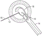
Referring to fig. 1 and 2, such prior art type cataract surgery involves the use of a surgical microscope to view the interior of the eye through the cornea and iris of a patient. A surgeon typically makes two incisions 10, 12 in the patient's cornea, near the limbus, to enable surgical instruments to access the interior sections of the eye and implant an intraocular lens after the cataract lens has been removed. For example, IOL inserter 14 may be inserted through incision 10 and positioning device 16 may be inserted through incision 12.
The procedure typically involves creating a full circle of tears inboard of the center of the capsular bag (known as "capsulorhexis") and removing the torn circle of the capsular bag. The cataract lens is then removed using a phacoemulsifier, ultrasonic irrigation and aspiration instrument that breaks up the cataract and aspirates debris to remove the cataract.
The adherent cortical material attached to the inner surface of the capsular bag is then aspirated using an irrigation/aspiration instrument. Lens inserter 14 is then used to insert intraocular lens 18 and positioning device 16 or other device is used to position the intraocular lens within the capsular bag.
A recent advance in femtosecond laser instrumentation is to automate the process of making an entry incision and capsulorhexis as well as pre-cut cataracts, thereby making the cataract surgery procedure more accurate, safer and easier for the surgeon to perform.
Most current lens inserters are manually operated reusable instruments primarily with one of the two devices used to push the lens-an advancing screw or plunger. The pusher screw solution provides a steady smooth delivery of the lens, but is slow and requires the surgeon or an assistant to turn the manual pusher screw while the surgeon positions the tip of the instrument.
The plunger solution does not require an assistant because the surgeon uses the thumb to drive the lens forward, much like injecting medication from an injector. In addition, the surgeon can more easily control the delivery speed: moving quickly through less critical sections and decelerating for finer sections. A disadvantage of the plunger approach is that when the lens becomes stuck, causing the surgeon to push harder to resolve the blockage, the lens may move too hard and injure the patient.
Reusable instruments require reprocessing (cleaning and sterilization), resulting in additional instrument expense and an increased risk of Toxic Anterior Segment Syndrome (TASS) (www.cdc.gov/mmwr/preview/mmwrhtml/mm5625a2. htm).
In recent years, efforts have been made to perform such lens replacement surgery using a smaller corneal incision. For example, as schematically shown in the illustration of FIG. 3, the distal end of intraocular lens inserter 14 is typically fully inserted through incision 10 during insertion of intraocular lens 18.
However, referring to FIG. 4, surgeons have recently resorted to a "wound assist" technique in which only a small portion of the tip 20 of intraocular lens inserter 14 is inserted into incision 10, where incision 10 is smaller than the incision previously formed (e.g., formed in the process illustrated in FIG. 3). Thus, intraocular lens 18 is pushed through incision 10 in its folded state and slides along the inner surface of the incision. This allows the incision 10 to be smaller and the wound itself (incision 10) becomes the cavity for inserting the lens 18 into the eye.
In such a procedure, the surgeon may use distal end 20 of the tip of IOL inserter 14 to help keep incision 10 open. For example, the surgeon may apply a lateral force in the direction of arrow 22 to hold incision 10 open so that lens 18 may be pushed therethrough.
There are a variety of intraocular devices used to implant the intraocular lenses described in the prior art. For example, WO 96/37152 describes a push rod in the housing which can be moved by pressure of the thumb. During axial advancement of the pushrod, the intraocular lens may be removed from the housing and implanted in the eye. A spring and/or damping element made of elastic rubber or plastic material acts against the advancing direction of the push rod to adjust the force of the push rod. Also, EP0477466a1 describes a rotary drive which can be embodied as an electric machine, which acts on a push rod via a rod and a transmission. Thereby, the rotational motion is converted into a forward motion. An intraocular lens, particularly comprising a foldable intraocular lens (comprising a rubber-elastomeric material such as silicon), is positioned in an implantation tool that can be placed on an implantation device. The pushing rod movement in the axial advancement direction is transmitted to the intraocular lens in the implantation tool during the implantation procedure.
Disclosure of Invention
An aspect of at least one of the inventions disclosed herein includes implementing: an intraocular lens inserter may allow a surgeon to use one hand to actuate the inserter device and thereby release the lens therefrom, and may also reduce the amount of manual force that the surgeon must apply. For example, in some known conventional devices (e.g., plunger devices), the surgeon must apply significant manual force to the proximal end of the plunger in order to push the lens through the tip of the inserter device. This makes it more difficult for the surgeon to hold the device in the desired orientation and position during insertion. This problem is more pronounced in the surgical procedures that are used in the past (e.g., as described above with reference to fig. 4). Thus, an intraocular lens insertion device that provides an assisted release force may assist a surgeon in performing a surgical procedure as desired.
Another aspect of at least one of the inventions disclosed herein includes the implementation of: the significant cost of such devices can be reduced by using a plug-in device that incorporates a mechanism for storing energy to provide a release force.
Accordingly, by providing an intraocular lens inserter with an energy device that stores energy to provide a release force, the intraocular lens inserter is made more portable and avoids the need for a surgeon to purchase or rent a separate console.
Another aspect of at least one of the inventions disclosed herein includes the implementation of: the handheld intraocular lens inserter can be made to incorporate an energy device and a movement control actuator with sufficient simplicity that the resulting device can be designed as a single use device and is therefore disposable, thereby avoiding the cost of re-sterilization and potential cross-contamination. Thus, for example, an intraocular lens insertion device may include a compressible energy device and an actuator configured to work with a substantially incompressible fluid for controlling the release of energy stored by the energy device and the movement of downstream components (e.g., lens insertion rod/plunger).
Another aspect of at least one of the inventions disclosed herein includes the implementation of: a compressible energy device (e.g., a spring or compressed air) may provide a conventional and portable means for storing energy that can be output as force. However, such energy devices are more difficult to control to provide, for example, a uniform output.
Another aspect of at least one of the inventions disclosed herein includes the implementation of: providing the damping medium with a substantially incompressible fluid (e.g., a liquid) accommodates the use of mechanisms that can provide finer control over the velocity of downstream components even where energy is supplied by a compressible storage device (e.g., a spring or compressed air).
This summary is provided to introduce a selection of concepts in a simplified form that are further described below in the detailed description. This summary is not intended to identify key features or essential features of the claimed subject matter, nor is it intended to be used as an aid in limiting the scope of the claimed subject matter.
Drawings
A more complete understanding of the subject matter may be derived by referring to the detailed description and claims when considered in conjunction with the following figures, wherein like reference numbers refer to similar elements throughout the figures.
FIG. 1 is an enlarged cross-sectional view of a human eye with an intraocular lens inserter inserted through an incision in the cornea and a positioning device inserted through a second incision, wherein a replacement intraocular lens is shown being partially ejected from the intraocular lens inserter.
Fig. 2 is a front plan view of the process shown in fig. 1.
FIG. 3 is a schematic view of a portion of the arrangement shown in FIG. 1 with the distal end of the intraocular lens inserter fully inserted through the incision and releasing the replacement lens.
FIG. 4 is a schematic illustration of a procedure different from that shown in FIG. 3 in which the distal end of the intraocular lens inserter is only partially inserted into the incision.
FIG. 5 is a schematic illustration of an embodiment of an intraocular lens inserter.
Fig. 6 is a schematic representation of an embodiment of the drive device of fig. 5.
Fig. 7 is a schematic illustration of an embodiment of the drive device with a slider of fig. 5.
Fig. 8 is a schematic illustration of an embodiment of the drive apparatus of fig. 7, wherein a two-phase pressurized gas is replaced with a single-phase pressurized gas.
Fig. 9 is a schematic illustration of an embodiment of the drive device of fig. 8, wherein pressurized gas is stored remotely from the device and delivered to the device via a conduit.
FIG. 10 is a perspective view of an additional embodiment of the intraocular lens inserter of FIG. 5.
FIG. 11 is a side elevational view and a cross-sectional view of the intraocular lens inserter of FIG. 10.
FIG. 12 is an exploded view of the lens cartridge holder portion of the intraocular lens inserter of FIG. 10.
FIG. 13 is an enlarged perspective and exploded view of the intraocular lens inserter shown in FIG. 12.
FIG. 14 is an enlarged side elevational view of the lens cartridge removed from the lens cartridge holding portion.
Fig. 15 is a view of the inserter of fig. 14 with a lens cartridge inserted into the lens cartridge holder portion.
Fig. 16 is a partial cross-sectional view of the inserter of fig. 15 before engagement of the lens cartridge with the plunger.
FIG. 17 is a cross-sectional view of the inserter shown after the lens holder portion has been moved axially to engage the plunger with the lens cartridge.
Detailed Description
The following detailed description is merely illustrative in nature and is not intended to limit the embodiments of the subject matter or the application and uses of such embodiments. As used herein, the word "exemplary" means "serving as an example, instance, or illustration. Any implementation described herein as "exemplary" is not necessarily to be construed as preferred or advantageous over other implementations. Furthermore, there is no intention to be bound by any expressed or implied theory presented in the preceding technical field, background, brief summary or the following detailed description.
Certain terminology may be used in the following description for the purpose of reference only and is therefore not intended to be limiting. For example, terms such as "upper," "lower," "above," and "below" refer to directions in the drawings to which reference is made. Terms such as "proximal," "distal," "front," "back," and "side" describe the orientation and/or position of various portions of the component within a uniform but arbitrary frame of reference that is made apparent by reference to the text and associated drawings describing the component in question. Such terminology may include the words above specifically mentioned, derivatives thereof, and words of similar import. Similarly, the terms "first," "second," and other such numerical words referring to structures do not imply a sequence or order unless clearly indicated by the context.
The inventions disclosed herein are described in the context of an intraocular lens inserter for the treatment of cataracts. However, the inventions disclosed herein may also be used in other contexts in relation to surgical devices that require placement of the device, for example, into or beyond the tissue of an animal (e.g., a human).
Generally described, aspects of the present disclosure relate to intraocular lens inserters including a drive device with controllable forward motion. The drive means may comprise actuator means and energy means. The actuator means may comprise a piston rod which uses the advancing movement to push out the intraocular lens from the cartridge for insertion into the eye of the animal. The energy means may act on the actuator means to generate the advancing movement. The actuator means may comprise a damping medium to control the forward movement, e.g. by controllably damping the forward movement.
In some embodiments, the piston rod may include a plunger portion, a piston portion, and a pushrod portion. The pushrod portion may be struck in the forward direction by pressurized gas provided by the energy device. The pressurized gas may be a single phase gas or a multi-phase gas, such as a liquefied two-phase gas. In some embodiments, for example involving the use of a liquefied two-phase gas, the pressurized gas component may function as a substantially constant force storage means. In some embodiments, the pressurized gas is stored entirely within the intraocular lens inserter. In some embodiments, the pressurized gas is stored remotely from the intraocular lens inserter. When the pressurized gas is stored remotely, the intraocular lens inserter may be supplied with pressurized gas from a conduit in fluid communication with the intraocular lens inserter.
The damping means applies a damping pressure to the piston portion opposite to the forward direction. The damping means may be a damping medium capable of flowing. For example, the damping medium may be a hydraulic fluid. In some embodiments, the damping medium may be an ophthalmically tolerable liquid. During implantation, the damping pressure applied to the piston portion counteracts the pressurized gas pressure applied to the push rod portion. Thus, the control of the movement of the plunger portion may be controlled by controlling the damping pressure applied to the piston portion.
For example, the energy device may release pressurized gas pressure on the pushrod to move the piston rod in the forward direction (by applying pressurized liquid pressure to the pushrod portion in the forward direction). However, the piston portion of the piston rod may be in contact with the damping medium in the pressure chamber for applying a damping pressure counteracting the pressurized gas pressure (by applying the damping pressure to the piston portion in a direction opposite to the advancing direction). Thus, control of the damping medium may be used to control the movement of the intraocular lens inserter (by controlling the reduction of the damping pressure, e.g. by draining the damping medium from the pressure chamber).
In some embodiments, a channel may be used to drain the damping medium from the pressure chamber. Thereby, the damping medium can be controlled by varying the cross-section of the channel. Also, a valve may be used to allow the damping medium to be discharged from the pressure chamber via the channel. Thereby, the damping medium may be controlled by changing the cross-section of the channel (e.g. by opening and/or closing the valve). In some embodiments, a slider may be used to control the cross-section of the channel and/or the valve may be controlled (e.g., by applying finger pressure to the slider) such that the pressurized gas is converted into a relaxed stroke for implanting the lens.
Referring to FIG. 5, intraocular lens inserter 100 may include an energy device 102, an actuator device 104, and a lens release device 106. The energy device 102 may be in the form of any type of energy device. In some embodiments, the energy device 102 is in the form of a device for storing energy (e.g., a compressible fluid), a mechanical spring, or other compressible type of energy storage device. Other types of energy storage devices may also be used. In some embodiments, the energy device 102 may receive and/or convert energy from an external source, such as by supplying pressurized gas from a conduit in fluid communication with the energy device.
In some embodiments, the energy device 102 may be configured to release mechanical energy from the energy therein. For example, where the energy device 102 is in the form of a container of compressed gas, the energy device 102 can release such compressed gas, thereby providing an output of mechanical energy. Furthermore, where the energy device 102 is in the form of an interface (e.g., a valve or connector) for a conduit that supplies pressurized gas from an energy source, the energy device 102 can release such pressurized gas, which provides an output of mechanical energy.
The actuator device 104 may be any type of actuator configured to provide controllable actuation of the mechanical energy output from the energy device 102. For example, in some embodiments, the actuator device 104 includes a user interface (e.g., a mechanical or electronic button, lever, or slider) to provide a means for a user to control the mechanical energy output of the energy device 102. For example, the actuator device 104 may include a slider, lever, or button configured to control a variable resistance or motion damping to the pressurized gas pressure applied to the piston rod from the energy device 102. Actuator device 104 may also control the interaction of the piston rod with lens release device 106. For example, the actuator device 104 may include an output plunger portion or other device for interacting with the lens release 106.


Thus, in operation, the actuator device 104 can be manipulated by a user, such as a surgeon, to control the mechanical energy output of the energy device 102 to thereby control the release of a lens from a lens cartridge housed by the lens release device 106. Additionally, in various embodiments, intraocular lens inserter 100 may be configured to be hand-held, disposable, and/or reusable.
In some embodiments, the actuator device 104 and the energy device 102 may be referred to in combination as a drive device 200. Referring to FIG. 6, intraocular lens inserter 100 may include an additional embodiment of a drive device 200A that includes an actuator device 104A and an energy device 102A. Features and components of the drive device 200A, including the actuator device 104A and the energy device 102A, which are identified by the same reference numerals, except for the addition of the letter "a," may be the same or similar to corresponding components of the drive device 200, including the actuator device 104 and the energy device 102.
Fig. 6 is a cross-sectional illustration of an embodiment of a drive device 200A by which a plunger portion 600 of a piston rod 615 in a housing 602 can be moved in an advancing direction 604. Pressurized gas 606 (e.g., a liquefied two-phase gas having a liquid component 606A and a gaseous component 606B) is stored entirely within housing 602.
In some embodiments, the pressurized gas 606 may serve as a constant energy storage device for the energy device 102A. The pressurized gas 606 acts on one side on a push rod portion 608, which is displaceably supported in the housing 602 in a gas-tight or generally gas-tight manner via an O-ring 610.
At the other side of the piston 612, a pressure chamber 616 contains a damping medium 618. The damping medium 618 may be flowable and may be in the form of a hydraulic fluid. In the idle state, the valve 620, for example at the sealing plug 622, is closed. When the valve 620 is closed, the pressure chamber 616 is sealed in an airtight or generally airtight manner from the exterior of the pressure chamber 616. To this end, a seal, for example in the form of a further O-ring 624, is provided at the sealing plug 622. Also, a piston rod 615 is also guided in the sealing plug 622 in an airtight or generally airtight manner. This is done with the aid of a further seal, which may also be implemented as an O-ring 625.
In the exemplary embodiment, channel 626 may be coupled to valve 620. The channel 626 may terminate at an exhaust chamber 628. Damping medium 618 may thereby be discharged from pressure chamber 616 via this channel 626. However, in other embodiments, the channel 626 may discharge the damping medium to another collection vessel (not shown) instead of the discharge chamber 628 or with the discharge chamber 628.
In this idle state (when the valve 620 is closed), the gas component 606B of the pressurized gas 606 acts on the piston rod 615 via the push rod portion 608. However, the damping medium resists movement of the piston portion 612 in the forward direction (the damping medium may be an incompressible or substantially incompressible fluid, such as a liquid including, for example, saline).
Opening the valve 620 allows the damping medium 618 to flow through the channel 626 into the exhaust chamber 628. This allows the gas component 606A of the pressurized gas 606 to drive the piston rod 615 in the forward direction 604. This causes damping medium 618 in pressure chamber 616 to displace through open valve 620 and passage 626 into discharge chamber 628. To limit the forward motion of the piston 612, a stop 630 may be positioned in the pressure chamber 616.
Pressure may be applied to the plunger portion 600 for retracting the piston portion 612 opposite the advancing direction 604. By applying pressure to the plunger portion 600 opposite to the advancing direction 604, damping medium may be accumulated in the pressure chamber 616 by suction and the pressurized gas 606 may be recompressed. When the piston portion 612 is retracted, a vacuum is created in the pressure chamber 616 so that damping medium 618 may be drawn through the open valve 620. The pushrod portion 608 also reduces the volume of the liquefied two-phase gas. After retracting the piston portion 612 and causing the valve 620 to close, the drive 200A may be returned to the ready-to-use state.
In certain embodiments, the piston chamber 632 and the channel 626 may be filled with damping medium 618 such that movement of the piston 614 is equivalent to displacement of the damping medium 618 between the pressure chamber 616 and the exhaust chamber 628. In other embodiments, the pressure chamber 616 may be filled with the damping medium 618, while the discharge chamber 628 and/or the channel 626 and/or the collection vessel may comprise another medium than the damping medium 618 (e.g., a vacuum, a different damping medium, or the ambient environment of the drive device 200A).
The rate of displacement of the damping medium 618 (and thus the movement of the piston 612 and the plunger 600) may be controlled by adjusting the cross-section of the valve 620, the cross-section of the passage 626, and/or the viscosity of the damping medium 618. For example, a user interface (e.g., a slider as discussed further below) may be utilized to control the rate of displacement of the damping medium. Thus, the speed of advancement of the piston rod 615 may be controlled so as to smoothly eject the intraocular lens from the cartridge for insertion into the eye.
Fig. 7 is a cross-sectional illustration of an exemplary embodiment of a drive device 200B. Referring to fig. 7, drive device 200B may be an additional embodiment of drive device 200A. Features and components of the drive device 200B may be the same or similar to corresponding components of the drive device 200A, except for the addition of the letter "B". As shown in fig. 7, the drive device 200B includes a channel 626B and a slider 700. Channel 626B may be formed from a flexible material such that the cross-section of channel 626B may be reduced and increased by applying pressure (e.g., pressure from a finger) to the surface of channel 626B. The slider 700 may be positioned over the channel 626B such that pressure of a finger on the slider 700 may control the cross-section of the channel. For example, the slider may include a plate that is vertically movable or deformable relative to the channel 626B.
Further, in some embodiments, the cross-section of the valve 620B may be controlled by the slider 700. For example, the cross-section of the valve 620B may be controlled such that the valve 620B is fully open, fully closed, or in any position between fully open or fully closed (e.g., by incrementally controlling the cross-section of the valve 620B). For example, a rod member (not shown) may connect the slider 700 to the valve 620B to control opening of the valve 620B, the valve 620B optionally being biased to a closed state when the slider 700 is in a zero state, and the valve 620B being opened as the slider 700 moves away from the zero state. In other embodiments, a separate user interface, such as an additional slider (not shown), may control the cross-sectional aperture of the valve 620B.
And in some embodiments, the viscosity of damping medium 618B may be selected and/or controlled to affect the rate of advancement of piston rod 615B. For example, different damping media may have different viscosities, such that movement of the piston portion 612B is a factor of the viscosity of the particular damping medium 618B used in the drive device 200B. Also, the viscosity may be controlled, for example, by controlling the temperature or another characteristic of the damping medium 618B to affect the rate of advance of the piston 612B.
Fig. 8 is a cross-sectional illustration of an exemplary embodiment of a drive device 200C. Referring to fig. 8, drive device 200C may be an additional embodiment of drive device 200B. Features and components of the drive device 200B may be the same or similar to features and components of the drive device 200C, except for the addition of the letter "C". As illustrated in fig. 8, pressurized gas 606 (which is a liquefied two-phase gas having a liquid component 606A and a gaseous component 606B) is replaced with pressurized gas 800 having a single phase.
Fig. 9 is a cross-sectional illustration of an exemplary embodiment of a drive device 200D. Referring to fig. 9, drive device 200D may be an additional embodiment of drive device 200B. Features and components of the drive device 200C may be the same or similar to features and components of the drive device 200B, except with the addition of the letter "D". As shown in fig. 9, pressurized gas 606, which is a liquefied two-phase gas having a liquid component 606A and a gaseous component 606B, is replaced with pressurized gas (not shown) stored remotely from drive device 200C. The remote source of pressurized gas may be delivered to the driver 200C via a conduit 902 in fluid communication with an interface 900 (e.g., a valve or connector) of the energy device 102D of the driver 200D.
Referring to FIGS. 10-17, an additional embodiment of intraocular lens inserter 100 is shown and designated by reference numeral 100E. Features and components of lens inserter 100E may be the same or similar to corresponding components of lens inserter 100 and have been labeled with the same reference numerals, except with the addition of the letter "E".
FIG. 10 is a perspective view of an additional embodiment of intraocular lens inserter 100 of FIG. 5. As illustrated in FIG. 10, intraocular lens inserter 100E also includes an energy device 102E, an actuator device 104E, and a lens device 106E. Intraocular lens inserter 100E may include a body portion 201 that includes a plurality of different cavities, recesses, and conduits and in this embodiment provides communication between energy storage portion 102A and actuator portion 104A and lens device 106E. In some embodiments, the body portion 201 may optionally be made of a single piece of material to form a unitary body. However, other configurations may also be used.
As shown, the lens device 106E may include a cartridge receiving portion 430 configured to receive the lens cartridge 400. The lens device 106E may also include a cartridge engagement member 240 configured to connect the lens device 106E and the actuator device 104E. The actuator device 104E may include a slider 700E. Also, the energy device 102E may include a removable cover 256.
FIG. 11 is a side elevational view and a cross-sectional view of the intraocular lens inserter of FIG. 10. As shown in fig. 11, the removable cap 256 may be removed to insert the compressed air container into the receiving portion 202. The receiving portion may be configured as a recess within the body portion 201, sized and configured to receive the compressed gas container. In some embodiments, the recess 202 may be sized to receive the compressed carbon dioxide canister 204. Such compressed gas (in particular carbon dioxide) vessels are widely commercially available.
Referring to fig. 12 and 13, cartridge engagement member 240 may include a cartridge receiving portion 430. For example, cartridge receiving portion 430 may include a distal tab engaging portion 432 and a body receiving portion 434. The tab receiving portion 432 and the body receiving portion 434 may be sized according to the outer dimensions of commercially available lens cartridges 400 well known in the art.
The distal flap engaging portion 432 may include a recess designed to engage the flap 436 of the lens cartridge 400. Thus, when the cartridge 400 is engaged with the cartridge receiving portion 430 as shown in fig. 10, the cartridge 400 is generally aligned with the plunger 600E.
With continued reference to fig. 14 and 15, cartridge receiving portion 430 may optionally include a proximal engagement portion 440 configured to engage a proximal portion of cartridge 400. For example, in some commercial embodiments of the cassette 400, the cassette 400 includes a trailing tab 442 or other trailing surface. The cassette engaging portion 430 may therefore comprise further proximal recesses 444 and engaging means 446 for forced engagement with the tabs 442. Thus, as shown in fig. 15, the cartridge 400 is more securely seated within the cartridge receiving portion 430 when the cartridge 400 is engaged with both the forward engaging portion 432 and the rearward engaging portion 444, with the projection 446 extending over the rearward tab 442.
This may provide significant benefits to the surgeon using inserter 100E. For example, because the projection 446 extends above the trailing tab 442, if a surgeon applies a force to the inserter 100E in the direction of arrow F (FIG. 15), a torque T will be generated or applied on the cartridge 400, thereby tending to cause the cartridge to pivot about the distal receiving portion 432, which thereby may tend to cause the proximal end of the cartridge 400 to rise upwardly in the direction of arrow U. However, the engagement portion 446 may help retain a proximal portion of the cartridge 400 within the receiving portion 430. This type of force may be generated during the performance of surgical procedures that are becoming more and more common, such as described above with reference to fig. 4, referred to as "wound assistance".
With continued reference to fig. 13-15, the cartridge engagement member 240 may also be slidably engaged with the body portion 201. Thus, the cartridge engagement member 240 may include a plurality of different inner surfaces configured to cooperate with the outer surface of the body portion 201. Thus, cartridge engaging member 240 may slide longitudinally along body portion 201, parallel to longitudinal axis L of intraocular lens inserter 100E.
For example, referring to fig. 16 and 17, the portion 240 may be moved to the distal position shown in fig. 16. In this position, lens receiving portion 430 is spaced from plunger 600E. In this way, the cartridge 400 can be inserted into the cartridge receiving part 430 without being interfered by the plunger 600E. Thus, after the cartridge is so received (as shown in fig. 17), cartridge engaging member 240 can be slid rearwardly relative to body portion 201 until plunger 600E engages or presses against the lens in cartridge 400.
As noted above, the body portion 201 may include a plurality of different detents or ramps or other portions 246, 248 that may engage a portion of the cartridge engagement member 240 for positive engagement into a plurality of different positions. For example, the cartridge engagement member 240 may include a ramp and hook portion 460 configured for engagement with the portions 246 and 248 of the body portion 201. Thus, the cartridge engaging member 240 may be forcibly engaged with the body portion 201 in the position shown in fig. 17, and then, upon pulling in the proximal direction to move the plunger 600E into the cartridge 400, the portion 460 may engage with the proximal portion of the housing 201 to thereby be engaged into the retracted position. Other designs may also be used to provide for conventional insertion and removal of the cassette 400.
While at least one exemplary embodiment has been presented in the foregoing detailed description, it should be appreciated that a vast number of variations exist. It should also be appreciated that the exemplary embodiment or exemplary embodiments described herein are not intended to limit the scope, applicability, or configuration of the claimed subject matter in any way. Rather, the foregoing detailed description will provide those skilled in the art with a convenient road map for implementing the described embodiment or embodiments. It should be understood that various changes can be made in the function and arrangement of elements without departing from the scope defined by the claims, which includes known equivalents and foreseeable equivalents at the time of filing this patent application.
Claims (17)
1. A device for implanting an intraocular lens comprising:
a piston rod;
a pressurized gas device configured to apply pressurized gas pressure to the piston rod to move the piston rod from the retracted position to the extended position;
a compression chamber comprising a damping medium comprising a substantially incompressible fluid, the damping medium applying a damping pressure to the piston rod counteracting the pressurized gas pressure;
a passage configured to discharge the damping medium from the compression chamber;
a slider configured to vary a cross-sectional area of the channel to control a rate at which the damping medium is discharged from the compression chamber; and
an intraocular lens holding portion for holding an intraocular lens for insertion into an eye of an animal and aligned with the plunger rod such that the plunger rod is for pushing the intraocular lens out of the intraocular lens holding portion as the plunger rod is moved from the retracted position toward the extended position.
2. The device for implanting an intraocular lens of claim 1, wherein a speed of movement of the piston rod from the retracted position to the extended position is based on a rate of expulsion of the damping medium from the compression chamber.
3. The device for implanting an intraocular lens of claim 1, wherein the channel is configured to discharge the damping medium into a discharge chamber separated from the compression chamber by the piston rod.
4. The device for implanting an intraocular lens of claim 3, wherein the discharge chamber, the channel, and the compression chamber are filled with the damping medium.
5. A device for implanting an intraocular lens comprising:
a piston rod;
a pressurized gas device configured to apply pressurized gas pressure to the piston rod to move the piston rod from the retracted position to the extended position;
a compression chamber comprising a damping medium, the damping medium comprising a substantially incompressible fluid and the damping medium applying a damping pressure to the piston rod counteracting the pressurized gas pressure;
a passage configured to discharge the damping medium from the compression chamber;
a valve configured to close or open the passage; and
an intraocular lens holding portion for holding an intraocular lens for insertion into an eye of an animal and aligned with the plunger rod such that the plunger rod is for pushing the intraocular lens out of the intraocular lens holding portion as the plunger rod is moved from the retracted position toward the extended position.
6. The device for implanting an intraocular lens of claim 5, comprising a slider configured to control the valve.
7. The device for implanting an intraocular lens of claim 6, wherein the slider is configured to vary a cross-sectional area of the channel to control a rate at which the damping medium is expelled from the compression chamber.
8. The device for implanting an intraocular lens of claim 6, wherein the slider is configured to vary a cross-sectional area of the channel based on pressure applied to the slider.
9. The device for implanting an intraocular lens of claim 6, comprising a second slider configured to vary a cross-sectional area of the channel to control a rate at which the damping medium is expelled from the compression chamber.
10. The device for implanting an intraocular lens of claim 5, wherein the channel is configured to discharge the damping medium into a discharge chamber.
11. The device for implanting an intraocular lens of claim 10, wherein the evacuation chamber comprises a vacuum.
12. The device for implanting an intraocular lens of claim 5, wherein the pressurized gas device comprises a single phase gas.
13. The device for implanting an intraocular lens of claim 5, wherein the pressurized gas device comprises a multi-phase gas.
14. The device for implanting an intraocular lens of claim 13, wherein the multi-phase gas is a two-phase gas comprising a gas component and a liquid component.
15. The device for implanting an intraocular lens of claim 5, wherein the pressurized gas device is located within a housing comprising the piston rod.
16. The device for implanting an intraocular lens of claim 5, wherein the pressurized gas device comprises a conduit in fluid communication with a source of pressurized gas located outside a housing comprising the piston rod.
17. The device for implanting an intraocular lens of claim 5, wherein moving the piston rod from the extended position to the retracted position moves the damping medium from the channel into the compression chamber.
Applications Claiming Priority (3)
| Application Number | Priority Date | Filing Date | Title |
|---|---|---|---|
| US201461975661P | 2014-04-04 | 2014-04-04 | |
| US61/975,661 | 2014-04-04 | ||
| PCT/US2015/024375 WO2015154049A1 (en) | 2014-04-04 | 2015-04-03 | Intraocular lens inserter |
Publications (2)
| Publication Number | Publication Date |
|---|---|
| CN106456372A CN106456372A (en) | 2017-02-22 |
| CN106456372B true CN106456372B (en) | 2020-01-21 |
Family
ID=54208723
Family Applications (1)
| Application Number | Title | Priority Date | Filing Date |
|---|---|---|---|
| CN201580018863.4A Active CN106456372B (en) | 2014-04-04 | 2015-04-03 | Intraocular lens inserter |
Country Status (8)
| Country | Link |
|---|---|
| US (3) | US10010408B2 (en) |
| EP (1) | EP3125840B1 (en) |
| JP (1) | JP6599889B2 (en) |
| CN (1) | CN106456372B (en) |
| AU (1) | AU2015240545B2 (en) |
| CA (1) | CA2944513C (en) |
| ES (1) | ES2871088T3 (en) |
| WO (1) | WO2015154049A1 (en) |
Families Citing this family (28)
| Publication number | Priority date | Publication date | Assignee | Title |
|---|---|---|---|---|
| US9554940B2 (en) | 2012-03-26 | 2017-01-31 | Glaukos Corporation | System and method for delivering multiple ocular implants |
| AU2013271703B2 (en) | 2012-06-04 | 2017-05-11 | Alcon Inc. | Intraocular lens inserter |
| CN106413634B (en) | 2013-11-01 | 2019-03-05 | 雷恩斯根公司 | Double component modulability intraocular lens equipment |
| US10010408B2 (en) | 2014-04-04 | 2018-07-03 | Alcon Pharmaceuticals, Ltd. | Intraocular lens inserter |
| US10182906B2 (en) * | 2014-07-15 | 2019-01-22 | Alcon Pharmaceuticals, Ltd. | Intraocular lens inserter with temperature compensation |
| US10004596B2 (en) | 2014-07-31 | 2018-06-26 | Lensgen, Inc. | Accommodating intraocular lens device |
| WO2016172113A1 (en) * | 2015-04-19 | 2016-10-27 | Atrion Corporation | Spring-powered, hydraulically-operate intraocular lens inserter |
| CN105287097B (en) * | 2015-10-29 | 2017-09-15 | 遂宁市中心医院 | Ophthalmology silicone oil extraction apparatus |
| US10172706B2 (en) | 2015-10-31 | 2019-01-08 | Novartis Ag | Intraocular lens inserter |
| JP6900376B2 (en) | 2015-12-01 | 2021-07-07 | レンスゲン、インコーポレイテッド | Adjustable intraocular lens device |
| USD841164S1 (en) | 2015-12-16 | 2019-02-19 | Novartis Ag | Intraocular lens delivery device |
| US11547555B2 (en) | 2015-12-17 | 2023-01-10 | Atrion Medical Products, Inc. | Intraocular lens delivery device and method of use |
| US10722347B2 (en) | 2015-12-17 | 2020-07-28 | Atrion Medical Products, Inc. | Intraocular lens delivery device and method of use |
| US10610351B2 (en) | 2016-03-08 | 2020-04-07 | Picocyl | Gas canisters and methods for making them |
| US11867359B2 (en) * | 2016-03-08 | 2024-01-09 | Picocyl, Llc | Gas canisters and methods for making them |
| ES2886966T3 (en) | 2016-04-29 | 2021-12-21 | Altaviz Llc | self-powered syringe |
| US10555834B2 (en) | 2016-07-11 | 2020-02-11 | Novartis Ag | Vitrectomy probe with rotary cutter and associated devices, systems, and methods |
| USD940865S1 (en) * | 2016-08-15 | 2022-01-11 | Board Of Regents, The University Oftexas System | Allograft insertion device |
| US11000367B2 (en) | 2017-01-13 | 2021-05-11 | Alcon Inc. | Intraocular lens injector |
| EP4052686A1 (en) * | 2017-05-04 | 2022-09-07 | Carl Zeiss Meditec Cataract Technology Inc. | Devices for ocular surgery |
| WO2019070385A2 (en) * | 2017-10-06 | 2019-04-11 | Glaukos Corporation | Systems and methods for delivering multiple ocular implants |
| JP7405761B2 (en) | 2018-03-28 | 2023-12-26 | ボシュ・アンド・ロム・インコーポレイテッド | Injector assembly that uses compressed gas and a mechanical brake to inject an intraocular lens into a patient |
| CN108524095A (en) * | 2018-04-16 | 2018-09-14 | 温州医科大学 | A kind of ocular implantation material injection device |
| US10849739B2 (en) * | 2018-08-02 | 2020-12-01 | Carl Zeiss Meditec Ag | Ophthalmosurgical injector system |
| CN113347945A (en) * | 2019-01-22 | 2021-09-03 | 卡尔蔡司医疗技术股份公司 | Intraocular lens injector with velocity modulation |
| WO2020261008A1 (en) * | 2019-06-27 | 2020-12-30 | Alcon Inc. | Iol base compression device having an iol towing mechanism |
| CN110236782B (en) * | 2019-07-02 | 2020-06-30 | 北京华视诺维医疗科技有限公司 | Aqueous humor collecting device |
| JP2024505032A (en) | 2021-01-29 | 2024-02-02 | アルコン インコーポレイティド | Ratchet drive delivery of surgical implants |
Family Cites Families (265)
| Publication number | Priority date | Publication date | Assignee | Title |
|---|---|---|---|---|
| US2547099A (en) | 1948-03-11 | 1951-04-03 | Becton Dickinson Co | Injection device and ampoule |
| US4429421A (en) | 1982-02-03 | 1984-02-07 | Levy Chauncey F | Method of implanting an intraocular lens |
| US4573998A (en) | 1982-02-05 | 1986-03-04 | Staar Surgical Co. | Methods for implantation of deformable intraocular lenses |
| US4619256A (en) | 1982-09-08 | 1986-10-28 | Gerald Horn | Intraocular lens inserting assembly |
| US4615703A (en) | 1983-07-22 | 1986-10-07 | Cilco, Inc. | Intraocular lens delivery system |
| US4634423A (en) | 1984-04-30 | 1987-01-06 | Bailey Jr Paul F | Ophthalmological method and instrument for implantation of posterior chamber intraocular lens |
| US4699140A (en) | 1985-07-10 | 1987-10-13 | Iolab Corporation | Instrument for inserting an intraocular lens |
| US4726367A (en) | 1985-08-19 | 1988-02-23 | Shoemaker David W | Surgical instrument for implanting an intraocular lens |
| US4715373A (en) | 1985-09-27 | 1987-12-29 | Mazzocco Thomas R | Devices for implantation of deformable intraocular lens structures |
| US4919130A (en) | 1986-11-07 | 1990-04-24 | Nestle S.A. | Tool for inserting compressible intraocular lenses into the eye and method |
| US4852566A (en) | 1986-11-07 | 1989-08-01 | Callahan Wayne B | Device for implantation of intraocular lens |
| US4747404A (en) | 1986-11-10 | 1988-05-31 | Kresge Eye Institute Of Wayne State University | Foldable intraocular lens inserter |
| US4763650A (en) | 1987-01-20 | 1988-08-16 | Hauser Stephen G | Instrument for inserting a deformable lens into the eye |
| US4765329A (en) | 1987-10-19 | 1988-08-23 | Cumming, Redwitz & Wilson, Inc. | Intraocular lens insertion instrument |
| US4986827A (en) * | 1987-11-05 | 1991-01-22 | Nestle S.A. | Surgical cutting instrument with reciprocating inner cutter |
| US4844065A (en) | 1987-11-06 | 1989-07-04 | Faulkner Gerald D | Intraocular lens inserting tool and method |
| US4844093A (en) | 1987-11-30 | 1989-07-04 | Kresge Eye Institute | Tool for folding and inserting intraocular lenses |
| US4880000A (en) | 1987-12-15 | 1989-11-14 | Iolab Corporation | Lens insertion instrument |
| US4934363A (en) | 1987-12-15 | 1990-06-19 | Iolab Corporation | Lens insertion instrument |
| US4822360A (en) | 1988-03-16 | 1989-04-18 | University Of Utah | Inflatable, intraocular lens and method of implanting the lens in the capsule of an eye |
| US4862885A (en) | 1988-05-25 | 1989-09-05 | Cumming J Stuart | Instrument for inserting a deformable intraocular lens into the eye |
| US5066297A (en) | 1989-01-23 | 1991-11-19 | Cumming J Stuart | Intraocular lens insertion device |
| US4906247A (en) | 1989-03-06 | 1990-03-06 | Fritch Charles D | Intraocular lens insertion system |
| US5098439A (en) | 1989-04-12 | 1992-03-24 | Allergan, Inc. | Small incision intraocular lens insertion apparatus |
| US5222972A (en) | 1989-04-12 | 1993-06-29 | Allergan, Inc. | Small incision intraocular lens insertion apparatus |
| US5007913A (en) | 1989-09-19 | 1991-04-16 | Alcon Surgical, Inc. | Apparatus and method for implantation of intraocular lenses |
| US5064413A (en) * | 1989-11-09 | 1991-11-12 | Bioject, Inc. | Needleless hypodermic injection device |
| AU6550990A (en) | 1989-11-09 | 1991-05-16 | Bioject, Inc. | Needleless hypodermic injection device |
| US5172702A (en) * | 1989-11-24 | 1992-12-22 | Medical Device Technologies, Inc. | Disposable spring-loaded soft tissue biopsy apparatus |
| DE4030492C1 (en) | 1990-09-26 | 1991-09-05 | Adatomed Pharmazeutische Und Medizintechnische Gesellschaft Mbh, 8000 Muenchen, De | |
| US5123905A (en) | 1991-06-07 | 1992-06-23 | Kelman Charles D | Intraocular lens injector |
| US5190552A (en) | 1992-02-04 | 1993-03-02 | Kelman Charles D | Slotted tube injector for an intraocular lens |
| US5304182A (en) | 1992-09-23 | 1994-04-19 | Kabi Pharmacia Ophthalmics, Inc. | Apparatus and method for curling and inserting flexible intraocular lenses |
| DE69331807T2 (en) | 1992-09-30 | 2002-09-26 | Vladimir Feingold | INTRAOCULAR LENS INSERTION SYSTEM |
| US5876440A (en) | 1992-09-30 | 1999-03-02 | Staar Surgical Company, Inc. | Methods of implantation of deformable intraocular lens |
| US6056757A (en) | 1992-09-30 | 2000-05-02 | Staar Surgical Company, Inc. | Implantation device with deformable nozzle tip for implanting a deformable intraocular lens |
| US5860984A (en) | 1992-09-30 | 1999-01-19 | Staar Surgical Company, Inc. | Spring biased deformable intraocular injecting apparatus |
| US5772666A (en) | 1992-09-30 | 1998-06-30 | Staar Surgical Company, Inc. | Deformable intraocular lens injecting apparatus with deformable tip plunger |
| US6712848B1 (en) | 1992-09-30 | 2004-03-30 | Staar Surgical Company, Inc. | Deformable intraocular lens injecting apparatus with transverse hinged lens cartridge |
| US5807400A (en) | 1992-09-30 | 1998-09-15 | Staar Surgical Company, Inc. | Deformable intraocular lens insertion system |
| US5616148A (en) | 1992-09-30 | 1997-04-01 | Staar Surgical Company, Inc. | Transverse hinged deformable intraocular lens injecting apparatus |
| US6506195B2 (en) | 1992-09-30 | 2003-01-14 | Staar Surgical Company, Inc. | Deformable intraocular lens insertion system |
| US5468246A (en) | 1993-07-02 | 1995-11-21 | Iovision, Inc. | Intraocular lens injector |
| JP3459664B2 (en) | 1993-07-15 | 2003-10-20 | キヤノンスター株式会社 | Deformable intraocular lens insertion device |
| WO1995013766A1 (en) | 1993-11-18 | 1995-05-26 | Allergan, Inc. | Deformable lens insertion apparatus |
| US5582613A (en) | 1993-11-18 | 1996-12-10 | Allergan | Apparatus and methods for controlled insertion of intraocular lenses |
| US6174315B1 (en) * | 1994-02-15 | 2001-01-16 | Staar Surgical Company, Inc. | Spring biased deformable intraocular injecting apparatus |
| US5629577A (en) | 1994-07-15 | 1997-05-13 | Micro Medical Devices | Miniature linear motion actuator |
| CA2173609C (en) | 1994-08-05 | 2006-06-20 | Dennis Alexander Figueroa | Device for inserting a flexible intraocular lens |
| ATE245012T1 (en) | 1994-11-18 | 2003-08-15 | Vladimir Feingold | DISPOSABLE INTRAOCULAR LENS INTRODUCTION SYSTEM |
| US5803925A (en) | 1995-01-17 | 1998-09-08 | Allergan | IOL insertion apparatus with covalently bonded lubricant |
| DE19505761C1 (en) | 1995-02-20 | 1996-04-25 | Klaas Dieter | Grip or forceps used when implanting intra=ocular lenses |
| JPH11510711A (en) * | 1995-05-24 | 1999-09-21 | ジェイ. チャンバーズ,トーマス | Injection system and method for use of a deformable intraocular lens |
| US5643276A (en) | 1995-10-10 | 1997-07-01 | Allergan | Apparatus and method for providing desired rotational orientation to an intraocular lens |
| US5693057A (en) | 1995-10-27 | 1997-12-02 | Dusek; Vaclav | Instrument for implanting foldable intraocular lenses |
| US5735858A (en) | 1996-01-26 | 1998-04-07 | Allergan | IOL insertion apparatus and method for using same |
| US5776138A (en) | 1996-01-26 | 1998-07-07 | Allergan | Apparatus and methods for IOL insertion |
| DE19624446C1 (en) * | 1996-06-19 | 1998-03-26 | Ferton Holding | Surgical instrument for mechanical removal of bone cement, and method for generating shock waves |
| US5716364A (en) | 1996-07-10 | 1998-02-10 | Allergan | IOL insertion apparatus and method for making and using same |
| US6083230A (en) | 1997-07-30 | 2000-07-04 | Allergan | Method for making IOL insertion apparatus |
| US5876406A (en) | 1996-08-02 | 1999-03-02 | Staar Surgical Company, Inc. | Deformable intraocular lens injecting apparatus with transverse hinged lens cartridge |
| US5944725A (en) | 1996-09-26 | 1999-08-31 | Bausch & Lomb Surgical, Inc. | Method and apparatus for inserting a flexible membrane into an eye |
| US6503275B1 (en) | 1996-11-15 | 2003-01-07 | Medevec Licensing, B.V. | Ophthalmic lens insertion instrument and package |
| US5947975A (en) | 1997-03-07 | 1999-09-07 | Canon Staar Co., Inc. | Inserting device for deformable intraocular lens |
| US5944674A (en) | 1997-11-03 | 1999-08-31 | Johnson & Johnson Professional, Inc. | Controlled tack polyurethane casting tape |
| US5921989A (en) | 1998-02-12 | 1999-07-13 | Allergan | Lens protector for intraocular lens inserter |
| US6497708B1 (en) | 1998-05-11 | 2002-12-24 | Medevec Licensing, B.V. | Intraocular lens insertion instrument |
| US6371960B2 (en) | 1998-05-19 | 2002-04-16 | Bausch & Lomb Surgical, Inc. | Device for inserting a flexible intraocular lens |
| US5947976A (en) | 1998-06-02 | 1999-09-07 | Alcon Laboratories, Inc. | Asymmetric intraocular lens injection cartridge |
| DE69928012T2 (en) | 1998-12-18 | 2006-07-27 | BioValve Technologies, Inc., Watertown | INJECTION DEVICE |
| DE19904220C2 (en) | 1999-02-03 | 2001-08-30 | Helmut Binder | Injector for folding and inserting an intraocular lens, and containers for storing and transporting the injector |
| JP3040101B1 (en) | 1999-02-12 | 2000-05-08 | 毅 杉浦 | Ciliary sulcus pad in posterior chamber lens transciliary scleral stitch of the eyeball |
| FR2789890B1 (en) | 1999-02-22 | 2002-01-18 | Lab Contactologie Appl Lca | DEVICE FOR INJECTING AN INTRAOCULAR LENS IN FLEXIBLE MATERIAL |
| US6537281B1 (en) | 1999-03-22 | 2003-03-25 | Valdemar Portney | Corrective intraocular lens system, intraocular lenses, and lens handling and installation devices for use therewith |
| US6342058B1 (en) | 1999-05-14 | 2002-01-29 | Valdemar Portney | Iris fixated intraocular lens and instrument for attaching same to an iris |
| JP3728155B2 (en) | 1999-10-05 | 2005-12-21 | キヤノンスター株式会社 | Intraocular lens insertion system |
| JP3944555B2 (en) | 1999-10-06 | 2007-07-11 | キヤノンスター株式会社 | Intraocular lens insertion system |
| US6387101B1 (en) | 1999-10-22 | 2002-05-14 | Staar Surgical Company, Inc. | Deformable intraocular lens injecting apparatus and method |
| US6312433B1 (en) | 1999-10-22 | 2001-11-06 | Staar Surgical Company, Inc. | Deformable intraocular lens injecting apparatus and method |
| SE9904338D0 (en) | 1999-11-30 | 1999-11-30 | Pharmacia & Upjohn Ab | Intraocular lens implants |
| US6283976B1 (en) | 2000-05-05 | 2001-09-04 | Allergan Sales Inc. | Intraocular lens implanting instrument |
| AU2001273683A1 (en) | 2000-07-11 | 2002-01-21 | The Johns Hopkins University School Of Medicine | Device for inserting an injectable bag intraocular lens within a human eye |
| US6500181B1 (en) | 2000-10-17 | 2002-12-31 | Valdemar Portney | Instrument for folding and inserting anterior chamber intraocular lenses |
| GB0025611D0 (en) * | 2000-10-19 | 2000-12-06 | Duckworth & Kent Ltd | Tablet inserters |
| US6398789B1 (en) | 2000-10-19 | 2002-06-04 | Alcon Universal, Ltd. | Intraocular lens injector cartridge |
| EP1339442A4 (en) | 2000-11-30 | 2006-12-27 | Biovalve Technologies Inc | Injection systems |
| US6858040B2 (en) | 2001-01-25 | 2005-02-22 | Visiogen, Inc. | Hydraulic configuration for intraocular lens system |
| US6540754B2 (en) | 2001-01-26 | 2003-04-01 | Advanced Medical Optics, Inc. | Apparatus and method for multiply folding and inserting an intraocular lens in an eye |
| US6554839B2 (en) | 2001-01-26 | 2003-04-29 | Advanced Medical Optics, Inc. | Stepped IOL insertion cartridge for inserting an intraocular lens in an eye |
| CA2440983A1 (en) | 2001-03-14 | 2002-09-26 | Penjet Corporation | System and method for removing dissolved gas from a solution |
| FR2822055B1 (en) | 2001-03-16 | 2003-09-12 | Lab Contactologie Appl Lca | INTRAOCULAR LENS INJECTOR |
| US6537283B2 (en) | 2001-08-17 | 2003-03-25 | Alcon, Inc. | Intraocular lens shipping case and injection cartridge |
| JP3861138B2 (en) | 2001-09-04 | 2006-12-20 | キヤノンスター株式会社 | Intraocular lens insertion device |
| US7037312B2 (en) | 2001-09-07 | 2006-05-02 | Canon-Staar Co., Inc. | Insertion device for deformable intraocular lens |
| US6623458B2 (en) * | 2001-09-26 | 2003-09-23 | B. Braun Melsungen, Ag | Spring launched needle safety clip |
| GB0125506D0 (en) * | 2001-10-24 | 2001-12-12 | Weston Medical Ltd | Needle free injection method and apparatus |
| FR2833154B1 (en) | 2001-12-12 | 2004-11-19 | Ioltechnologie Production | CASSETTE AND FLEXIBLE INTRAOCULAR LENS INJECTOR AND METHOD FOR INJECTING SUCH LENSES |
| JP3791421B2 (en) | 2002-01-23 | 2006-06-28 | キヤノンスター株式会社 | Intraocular lens insertion device |
| US6723104B2 (en) | 2002-03-13 | 2004-04-20 | Advanced Medical Optics, Inc. | IOL insertion apparatus and method for using same |
| JP2003290271A (en) | 2002-04-01 | 2003-10-14 | Canon Star Kk | Intraocular lens insertion appliance |
| US6733507B2 (en) | 2002-04-12 | 2004-05-11 | Advanced Medical Optics, Inc. | Intraocular lens insertion apparatus |
| US7131976B2 (en) | 2002-05-08 | 2006-11-07 | Canon-Staar Co. Inc. | Insertion device for intraocular lens |
| JP2003325570A (en) | 2002-05-08 | 2003-11-18 | Canon Star Kk | System for inserting intraocular insertion lens |
| JP2003325572A (en) | 2002-05-08 | 2003-11-18 | Canon Star Kk | System for inserting intraocular insertion lens |
| US7014641B2 (en) | 2002-05-08 | 2006-03-21 | Canon-Staar Co., Inc. | Insertion device for intraocular lens |
| US6923815B2 (en) | 2002-05-14 | 2005-08-02 | Advanced Medical Optics, Inc. | Intraocular lens insertion apparatus |
| MXPA05002841A (en) | 2002-09-18 | 2005-05-27 | Oculex Pharm Inc | Methods and apparatus for delivery of ocular implants. |
| US20040059343A1 (en) | 2002-09-25 | 2004-03-25 | Kevin Shearer | Novel enhanced system for intraocular lens insertion |
| JP4138428B2 (en) | 2002-09-27 | 2008-08-27 | 株式会社ニデック | Intraocular lens insertion device |
| ES2305194T3 (en) | 2002-12-09 | 2008-11-01 | ANTON MEYER & CO. AG | EMBOLO WATER FOR AN INTRAOCULAR LENS INJECTOR. |
| JP4068479B2 (en) | 2003-02-28 | 2008-03-26 | 株式会社ニデック | Intraocular lens insertion device |
| FR2853223B1 (en) | 2003-04-01 | 2005-06-24 | Lab Contactologie Appl Lca | INTRAOCULAR LENS AND ITS INJECTOR |
| US7476229B2 (en) | 2003-04-07 | 2009-01-13 | Anton Meyer & Co. Ag | Cartridge for an intraocular lens |
| US20050033308A1 (en) | 2003-04-11 | 2005-02-10 | Callahan Wayne B. | Intraocular lens storage and insertion device and method of use thereof |
| US20060293694A1 (en) | 2003-05-27 | 2006-12-28 | Hoya Corporation | Injector |
| US20040267359A1 (en) | 2003-06-27 | 2004-12-30 | Harish Makker | IOL insertion apparatus and methods for making and using same |
| US7429263B2 (en) | 2003-08-28 | 2008-09-30 | Bausch & Lomb Incorporated | Preloaded IOL injector |
| US7422604B2 (en) | 2003-08-28 | 2008-09-09 | Bausch & Lomb Incorporated | Preloaded IOL injector |
| US20070060925A1 (en) | 2003-09-26 | 2007-03-15 | Joel Pynson | Preloaded iol injector and method |
| JP4590505B2 (en) | 2003-10-01 | 2010-12-01 | スター・ジャパン株式会社 | Intraocular lens insertion device |
| US8287584B2 (en) | 2005-11-14 | 2012-10-16 | Sadra Medical, Inc. | Medical implant deployment tool |
| US7276071B2 (en) | 2004-01-05 | 2007-10-02 | Board Of Supervisors Of Louisiana State University And Agricultural And Mechanical College | Intraocular lens injector |
| US7344517B2 (en) * | 2004-01-20 | 2008-03-18 | Becton, Dickinson And Company | Syringe having a retractable needle |
| US20050171555A1 (en) | 2004-01-30 | 2005-08-04 | Tran Son T. | Intraocular lens injector |
| US7645300B2 (en) | 2004-02-02 | 2010-01-12 | Visiogen, Inc. | Injector for intraocular lens system |
| US7717879B2 (en) | 2004-02-03 | 2010-05-18 | Smjm Inject Gmbh | Anesthetic syringe |
| US7458976B2 (en) | 2005-03-02 | 2008-12-02 | Advanced Medical Optics, Inc. | Devices and methods for storing, loading, and delivering an intraocular lens |
| US7625388B2 (en) | 2004-03-22 | 2009-12-01 | Alcon, Inc. | Method of controlling a surgical system based on a load on the cutting tip of a handpiece |
| US8535331B2 (en) | 2004-03-31 | 2013-09-17 | Bausch & Lomb Incorporated | IOL injector |
| US7947049B2 (en) | 2004-03-31 | 2011-05-24 | Bausch & Lomb Incorporated | IOL injector |
| US20080097459A1 (en) | 2004-04-22 | 2008-04-24 | Advanced Vision Science, Inc. | Device For The Insertion Of Deformable Intra-Ocular Lenses |
| US7717874B2 (en) | 2004-05-28 | 2010-05-18 | Bioject, Inc. | Needle-free injection system |
| US20050283163A1 (en) | 2004-06-04 | 2005-12-22 | Valdemar Portney | Intraocular lens implanting instrument |
| US20050283164A1 (en) | 2004-06-18 | 2005-12-22 | Henry Wu | Apparatus and method for implanting intraocular lens through a small incision |
| US20050283162A1 (en) | 2004-06-22 | 2005-12-22 | Stratas Byron A | Intraocular lens inserter |
| US20100057095A1 (en) | 2004-08-18 | 2010-03-04 | Leonid Orbachevsky | Method of Refraction Surgery of the Eye and a Tool for Implanting Intraocular Refractive Lens |
| US20060287655A1 (en) | 2004-08-18 | 2006-12-21 | Khuray Aslan R | Method for eye refractive surgery and device for implanting an intraocular refractive lens |
| US20060085013A1 (en) * | 2004-10-20 | 2006-04-20 | Vaclav Dusek | Intraocular lens inserter |
| ES2367787T3 (en) | 2004-11-30 | 2011-11-08 | BAUSCH & LOMB INCORPORATED | TWO-PHASE ENVIRONMENT FOR INTRAOCULAR LENS INJECTOR. |
| US8262605B2 (en) | 2004-12-09 | 2012-09-11 | Ams Research Corporation | Needleless delivery systems |
| WO2006070628A1 (en) | 2004-12-27 | 2006-07-06 | Hoya Corporation | Intraocular lens implanting device |
| US20060142780A1 (en) | 2004-12-29 | 2006-06-29 | Joel Pynson | Preloaded IOL injector and method |
| US20060142781A1 (en) | 2004-12-29 | 2006-06-29 | Joel Pynson | Preloaded IOL injector and method |
| US20060167466A1 (en) | 2005-01-21 | 2006-07-27 | Vaclav Dusek | Intraocular lens inserter system components |
| US8545512B2 (en) | 2005-01-26 | 2013-10-01 | Hoya Corporation | Intraocular lens insertion device |
| PL2058020T3 (en) | 2005-02-01 | 2013-03-29 | Kaleo Inc | Devices for medicament delivery |
| US8435289B2 (en) | 2005-02-11 | 2013-05-07 | Abbott Medical Optics Inc. | Rapid exchange IOL insertion apparatus and methods of using |
| US8562674B2 (en) | 2005-02-11 | 2013-10-22 | Abbott Medical Optics Inc. | Front loading IOL insertion apparatus and method of using |
| JP4836046B2 (en) | 2005-02-24 | 2011-12-14 | Hoya株式会社 | Intraocular lens insertion device |
| US8206345B2 (en) | 2005-03-07 | 2012-06-26 | Medtronic Cryocath Lp | Fluid control system for a medical device |
| US7892282B2 (en) | 2005-04-08 | 2011-02-22 | Abbott Medical Optics Inc. | Methods and apparatus for inserting an intraocular lens into an eye |
| US7892283B2 (en) | 2005-04-08 | 2011-02-22 | Abbott Medical Optics Inc. | Methods and apparatus for inserting an intraocular lens into an eye |
| US7740636B2 (en) | 2005-04-15 | 2010-06-22 | Abbott Medical Optics Inc. | Multi-action device for inserting an intraocular lens into an eye |
| US20060264971A1 (en) | 2005-05-18 | 2006-11-23 | Takayuki Akahoshi | Intraocular lens injection nozzle |
| JP4481878B2 (en) | 2005-05-31 | 2010-06-16 | 株式会社ニデック | Intraocular lens insertion device |
| DE102005042849A1 (en) | 2005-09-09 | 2007-03-22 | Kammann, Jochen, Prof. Dr. | Implantation tool for intraocular lenses |
| US8574239B2 (en) | 2005-09-28 | 2013-11-05 | Hoya Corporation | Intraocular lens insertion device |
| JP4877643B2 (en) | 2005-12-08 | 2012-02-15 | Hoya株式会社 | Intraocular lens insertion device |
| EP1800623A1 (en) | 2005-12-20 | 2007-06-27 | Canon-Staar Co., Inc. | Insertion device for intraocular lens |
| EP1800622A1 (en) | 2005-12-23 | 2007-06-27 | SDI Surgical Device International GmbH | Spring-biased injector for an intraocular lens |
| US20100286704A1 (en) | 2006-01-13 | 2010-11-11 | Hoya Corporation | Intraocular lens insertion device |
| CA2640239C (en) | 2006-01-26 | 2014-12-09 | Advanced Medical Optics, Inc. | Intraocular lens insertion apparatus and lens case |
| WO2007098622A1 (en) | 2006-02-28 | 2007-09-07 | Sdi Surgical Device International Gmbh | Spring-biased injector for an intraocular lens |
| WO2007112130A2 (en) | 2006-03-28 | 2007-10-04 | Tissue Engineering Refraction, Inc. | Automatic epithelial delaminator and lens inserter |
| JP4727497B2 (en) | 2006-05-17 | 2011-07-20 | スター・ジャパン株式会社 | Lens insertion device for intraocular insertion |
| ATE474526T1 (en) | 2006-05-18 | 2010-08-15 | Staar Japan Inc | INTRAOCULAR LENS INSERTION DEVICE |
| US20080004610A1 (en) | 2006-06-30 | 2008-01-03 | David Miller | System for calculating IOL power |
| US8721702B2 (en) | 2010-11-15 | 2014-05-13 | Aquesys, Inc. | Intraocular shunt deployment devices |
| US20080027461A1 (en) | 2006-07-25 | 2008-01-31 | Vaquero Edward A | Intraocular Lens Inserter Plunger |
| JP4927473B2 (en) | 2006-08-11 | 2012-05-09 | 興和株式会社 | Intraocular lens insertion device |
| US8460375B2 (en) | 2006-08-14 | 2013-06-11 | Novartis Ag | Lens delivery system |
| WO2008023379A2 (en) | 2006-08-25 | 2008-02-28 | Nulens Ltd | Intraocular lens implantation kit |
| JP4908977B2 (en) | 2006-09-05 | 2012-04-04 | 興和株式会社 | Intraocular lens insertion device |
| US9681947B2 (en) | 2006-10-23 | 2017-06-20 | Novartis Ag | Intraocular lens delivery system with temperature control |
| US8900249B2 (en) | 2006-10-23 | 2014-12-02 | Novartis Ag | Method of delivering temperature controlled intraocular lens |
| US7993264B2 (en) | 2006-11-09 | 2011-08-09 | Ams Research Corporation | Orientation adapter for injection tube in flexible endoscope |
| US8114095B2 (en) | 2006-11-10 | 2012-02-14 | Bausch & Lomb Incorporated | Intraocular lens injection apparatus and method |
| US7879090B2 (en) | 2006-12-13 | 2011-02-01 | Bausch & Lomb Incorporated | Intraocular lens injector apparatus and methods of use |
| US20080147080A1 (en) | 2006-12-13 | 2008-06-19 | Joel Pynson | Injector apparatus for use with intraocular lenses and methods of use |
| US20080147082A1 (en) | 2006-12-13 | 2008-06-19 | Joel Pynson | Injector apparatus for use with intraocular lenses and methods of use |
| US20080269770A1 (en) | 2006-12-22 | 2008-10-30 | Joel Pynson | Intraocular Lens Injector Subassembly |
| US20080154361A1 (en) | 2006-12-22 | 2008-06-26 | Joel Pynson | Intraocular lens injector subassembly |
| US20080171968A1 (en) | 2007-01-15 | 2008-07-17 | Bioject, Inc. | Methods of administering injectables to a joint with a needle-free injection system |
| WO2008106421A2 (en) | 2007-02-27 | 2008-09-04 | Ast Products, Inc. | Instrument for injecting an ophthalmic device into an eye |
| US20080221585A1 (en) | 2007-03-09 | 2008-09-11 | Downer David A | Lens Delivery System Cartridge |
| EP2161005B1 (en) | 2007-05-30 | 2016-12-28 | Hoya Corporation | Intraocular lens inserting tool |
| JP5236637B2 (en) | 2007-05-30 | 2013-07-17 | Hoya株式会社 | Intraocular lens insertion device and intraocular lens insertion device |
| CN101677854B (en) | 2007-06-05 | 2012-08-29 | 视达日本有限公司 | Intraocular lens insertion instrument and intraocular lens packing insertion instrument |
| WO2008149978A1 (en) | 2007-06-06 | 2008-12-11 | Staar Japan., Inc. | Intraocular lens inserting tool, and intraocular lens housing type inserting tool |
| US20090005788A1 (en) | 2007-06-26 | 2009-01-01 | Rathert Brian D | Intraocular Lens Injector |
| JP5086713B2 (en) | 2007-07-11 | 2012-11-28 | Hoya株式会社 | Intraocular lens insertion device |
| US20090018548A1 (en) | 2007-07-13 | 2009-01-15 | Charles Steven T | Pneumatically-Powered Intraocular Lens Injection Device with Removable Cartridge |
| US8398651B2 (en) | 2007-07-17 | 2013-03-19 | Abbott Medical Optics, Inc. | Viscoelastic applicator for IOL insertion apparatus |
| GB0714005D0 (en) | 2007-07-18 | 2007-08-29 | Rayner Intraocular Lenses Ltd | Device for inserting an intraocular lens into a eye |
| US8968396B2 (en) | 2007-07-23 | 2015-03-03 | Powervision, Inc. | Intraocular lens delivery systems and methods of use |
| AU2008279173B2 (en) | 2007-07-23 | 2014-07-31 | Alcon Inc. | Lens delivery system |
| US20090112222A1 (en) | 2007-10-25 | 2009-04-30 | Bausch & Lomb Incorporated | IOL Insertion Apparatus |
| US8216629B2 (en) | 2007-10-29 | 2012-07-10 | Advanced Vision Science, Inc. | Lubricious intraocular lens insertion device |
| US8617099B2 (en) | 2007-11-26 | 2013-12-31 | Bioject Inc. | Injection device plunger auto-disable |
| JP5255832B2 (en) | 2007-12-28 | 2013-08-07 | 興和株式会社 | Intraocular lens insertion device |
| JP5189356B2 (en) | 2007-12-28 | 2013-04-24 | 興和株式会社 | Intraocular lens insertion device |
| US8425595B2 (en) | 2008-03-12 | 2013-04-23 | Visiogen, Inc. | Method for inserting an intraocular lens |
| US8702794B2 (en) | 2008-04-28 | 2014-04-22 | Abbott Medical Optics Inc. | Back loaded IOL insertion cartridge |
| US8439973B2 (en) | 2008-05-20 | 2013-05-14 | Amo Regional Holdings | Plungers for intraocular lens injectors |
| JP5254669B2 (en) | 2008-06-05 | 2013-08-07 | Hoya株式会社 | Intraocular lens insertion device and cartridge |
| US8062360B2 (en) | 2008-06-11 | 2011-11-22 | Bausch & Lomb Incorporated | Intraocular lens injector and method |
| JP5470753B2 (en) | 2008-06-17 | 2014-04-16 | Hoya株式会社 | Intraocular lens insertion device |
| US8273122B2 (en) | 2008-06-23 | 2012-09-25 | Abbott Medical Optics Inc. | Pre-loaded IOL insertion system |
| US8961601B2 (en) | 2008-07-09 | 2015-02-24 | Bausch & Lomb Incorporated | IOL injector comprising a moveable side wall |
| JP5323420B2 (en) | 2008-08-21 | 2013-10-23 | Hoya株式会社 | Intraocular lens insertion device |
| JP5416379B2 (en) | 2008-09-04 | 2014-02-12 | Hoya株式会社 | Intraocular lens insertion device |
| FR2935606B1 (en) | 2008-09-11 | 2010-09-03 | Patrick Meunier | INTRAOCULAR LENS INJECTION SYSTEM COMPRISING AN INJECTOR WITH A CARTRIDGE AND A LOADING DEVICE |
| KR100893138B1 (en) | 2008-09-19 | 2009-04-16 | 주식회사 알이티 | Injector for disposable intraocular lens |
| CH699588A1 (en) | 2008-09-22 | 2010-03-31 | Medicel Ag | Cartridge for an intraocular lens injector system and for it. |
| US20100087832A1 (en) | 2008-10-03 | 2010-04-08 | Seyboth William J | Intraocular lens injector |
| US8801780B2 (en) | 2008-10-13 | 2014-08-12 | Alcon Research, Ltd. | Plunger tip coupling device for intraocular lens injector |
| US8308736B2 (en) | 2008-10-13 | 2012-11-13 | Alcon Research, Ltd. | Automated intraocular lens injector device |
| US8808308B2 (en) | 2008-10-13 | 2014-08-19 | Alcon Research, Ltd. | Automated intraocular lens injector device |
| US20100106160A1 (en) | 2008-10-24 | 2010-04-29 | George Tsai | Intraocular lens injection systems and methods |
| TW201021778A (en) | 2008-11-12 | 2010-06-16 | Alcon Res Ltd | Intraocular lens delivery device with a multi-part plunger tip |
| US20100125278A1 (en) | 2008-11-19 | 2010-05-20 | Wagner Christopher E | Hard and Soft Tip Intraocular Lens Injector System and Method |
| TWI455734B (en) | 2008-11-20 | 2014-10-11 | Alcon Res Ltd | Intraocular lens delivery device having a cartridge with an internal coating |
| ES2723752T3 (en) | 2008-12-01 | 2019-08-30 | Kowa Co | Intraocular lens insertion tool |
| US9125737B2 (en) | 2008-12-18 | 2015-09-08 | Alcon Research, Ltd. | Constant force intraocular lens injector |
| CN102307543B (en) | 2009-01-07 | 2015-10-21 | Hoya株式会社 | Intraocular lens inserting instrument |
| NZ594436A (en) | 2009-02-11 | 2013-09-27 | Alcon Res Ltd | Automated intraocular lens injector device |
| US20100228260A1 (en) | 2009-03-04 | 2010-09-09 | Anew Optics, Inc. | Injector for intraocular lens |
| EP2408398B1 (en) | 2009-03-18 | 2014-06-25 | Ophthalmopharma AG | Device for holding folding and injecting an intraocular lens |
| US20100256651A1 (en) | 2009-04-07 | 2010-10-07 | Dharmendra Jani | Intraocular Lens Injector with Hydrophilic Coating |
| GB2470416A (en) | 2009-05-22 | 2010-11-24 | Rayner Intraocular Lenses Ltd | Intraocular Lens Cartridge |
| TWI513459B (en) | 2009-05-29 | 2015-12-21 | Alcon Res Ltd | Intraocular lens delivery system with a disposable plunger segment and method of use therefor |
| US8377076B2 (en) | 2009-06-09 | 2013-02-19 | Novartis Ag | Lens delivery system |
| GB2472873A (en) | 2009-08-18 | 2011-02-23 | Carl Zeiss Meditec Sas | Cassette for intraocular lens |
| GB2472872B (en) | 2009-08-18 | 2014-12-31 | Carl Zeiss Meditec Sas | Holding device for an intraocular lens, packaging and transport means for an intraocular lens and injector device for an intraocular lens. |
| GB2472871A (en) | 2009-08-18 | 2011-02-23 | Carl Zeiss Meditec Sas | Cassette for intraocular lens |
| ES2617979T3 (en) | 2009-11-17 | 2017-06-20 | Kowa Company Ltd. | Intraocular lens insertion device |
| GB2475568B (en) | 2009-11-20 | 2015-08-26 | Carl Zeiss Meditec Sas | Tip for intraocular lens injector |
| US20110152872A1 (en) | 2009-12-23 | 2011-06-23 | Seyboth William J | Intraocular lens injector including a shaped spring |
| US20110245840A1 (en) | 2010-03-31 | 2011-10-06 | Seyboth William J | Intraocular lens injector system |
| US8696682B2 (en) | 2010-04-02 | 2014-04-15 | Abbott Medical Optics Inc. | Intraocular lens insertion devices |
| US8308799B2 (en) | 2010-04-20 | 2012-11-13 | Alcon Research, Ltd. | Modular intraocular lens injector device |
| JP5809242B2 (en) | 2010-04-21 | 2015-11-10 | アッヴィ バイオテクノロジー リミテッド | Wearable automatic infusion device for controlled delivery of therapeutic agents |
| WO2011132199A1 (en) | 2010-04-22 | 2011-10-27 | Ram Srikanth Mirlay | Improved intraocular lens injecting apparatus |
| US8758433B2 (en) * | 2010-04-23 | 2014-06-24 | Abbott Medical Optics Inc. | Insertion mode phacoemulsification employing powered IOL delivery |
| CA2797245C (en) | 2010-04-23 | 2019-01-08 | Abbott Medical Optics Inc. | Intraocular lens temperature control system |
| US20130041382A1 (en) | 2010-05-06 | 2013-02-14 | Nulens Ltd. | Injector Apparatus for Injecting Intraocular Lens |
| KR101179976B1 (en) | 2010-06-16 | 2012-09-07 | 주식회사 알이티 | Injector for disposable intraocular lens |
| WO2012006616A2 (en) | 2010-07-09 | 2012-01-12 | Powervision, Inc. | Intraocular lens delivery devices and methods of use |
| KR101191295B1 (en) | 2010-07-15 | 2012-10-16 | 주식회사 알이티 | Injector for disposable intraocular lens |
| US8579969B2 (en) | 2010-07-25 | 2013-11-12 | Alcon Research, Ltd. | Dual mode automated intraocular lens injector device |
| EP2438945A1 (en) * | 2010-10-08 | 2012-04-11 | Sanofi-Aventis Deutschland GmbH | Reusable engine for an auto-injector |
| MX2013006657A (en) | 2010-12-20 | 2013-08-01 | Novartis Ag | Intraocular lens transfer case. |
| CN102151194B (en) * | 2011-01-31 | 2013-08-14 | 爱博诺德(北京)医疗科技有限公司 | Intraocular lens preassembled injector capable of being preassembled with viscoelastic agent and viscoelastic agent loading method |
| JP6071995B2 (en) | 2011-03-24 | 2017-02-01 | パワーヴィジョン・インコーポレーテッド | Intraocular lens loading system and method of use |
| WO2013086612A1 (en) | 2011-12-15 | 2013-06-20 | Socpra Sciences Et Genie S.E.C. | Mechanism for puncturing a gas cartridge |
| US8657835B2 (en) | 2012-01-27 | 2014-02-25 | Alcon Research, Ltd. | Automated intraocular lens injector device |
| AU2013271703B2 (en) | 2012-06-04 | 2017-05-11 | Alcon Inc. | Intraocular lens inserter |
| US10350059B2 (en) | 2012-12-05 | 2019-07-16 | Hoya Corporation | Ocular implant insertion apparatus and methods |
| US9402716B2 (en) | 2013-03-15 | 2016-08-02 | Abbott Medical Optics Inc. | Intraocular lens inserter and system and method regarding same |
| EP2923714A1 (en) | 2014-03-28 | 2015-09-30 | Sanofi-Aventis Deutschland GmbH | Autoinjector triggered by skin contact |
| BE1022246B1 (en) | 2014-03-28 | 2016-03-04 | Physiol S.A. | SYSTEM FOR CONTROLLING AN INTRAOCULAR INJECTOR |
| US10010408B2 (en) | 2014-04-04 | 2018-07-03 | Alcon Pharmaceuticals, Ltd. | Intraocular lens inserter |
| CN104127264B (en) * | 2014-06-19 | 2017-03-22 | 爱博诺德(北京)医疗科技有限公司 | One-step pre-loaded intraocular lens implantation system |
| US10182906B2 (en) | 2014-07-15 | 2019-01-22 | Alcon Pharmaceuticals, Ltd. | Intraocular lens inserter with temperature compensation |
| JP7042083B2 (en) | 2015-06-25 | 2022-03-25 | 興和株式会社 | Manufacturing method of intraocular lens insertion device, intraocular lens extrusion aid and intraocular lens insertion device |
-
2015
- 2015-04-03 US US14/678,826 patent/US10010408B2/en active Active
- 2015-04-03 CN CN201580018863.4A patent/CN106456372B/en active Active
- 2015-04-03 AU AU2015240545A patent/AU2015240545B2/en active Active
- 2015-04-03 JP JP2016560730A patent/JP6599889B2/en active Active
- 2015-04-03 WO PCT/US2015/024375 patent/WO2015154049A1/en active Application Filing
- 2015-04-03 ES ES15774395T patent/ES2871088T3/en active Active
- 2015-04-03 CA CA2944513A patent/CA2944513C/en active Active
- 2015-04-03 EP EP15774395.6A patent/EP3125840B1/en active Active
-
2018
- 2018-03-08 US US15/916,005 patent/US10905547B2/en active Active
-
2020
- 2020-12-23 US US17/133,128 patent/US20210113327A1/en active Pending
Also Published As
| Publication number | Publication date |
|---|---|
| AU2015240545A1 (en) | 2016-11-03 |
| EP3125840A4 (en) | 2017-05-31 |
| US20210113327A1 (en) | 2021-04-22 |
| US10010408B2 (en) | 2018-07-03 |
| JP6599889B2 (en) | 2019-10-30 |
| CA2944513A1 (en) | 2015-10-08 |
| US10905547B2 (en) | 2021-02-02 |
| US20180193134A1 (en) | 2018-07-12 |
| AU2015240545B2 (en) | 2019-07-11 |
| CN106456372A (en) | 2017-02-22 |
| EP3125840B1 (en) | 2021-03-24 |
| WO2015154049A1 (en) | 2015-10-08 |
| EP3125840A1 (en) | 2017-02-08 |
| US20150282928A1 (en) | 2015-10-08 |
| ES2871088T3 (en) | 2021-10-28 |
| JP2017509442A (en) | 2017-04-06 |
| CA2944513C (en) | 2022-07-05 |
Similar Documents
| Publication | Publication Date | Title |
|---|---|---|
| CN106456372B (en) | Intraocular lens inserter | |
| US10485657B2 (en) | Intraocular lens inserter | |
| JP6571753B2 (en) | Temperature compensated intraocular lens inserter |
Legal Events
| Date | Code | Title | Description |
|---|---|---|---|
| C06 | Publication | ||
| PB01 | Publication | ||
| C10 | Entry into substantive examination | ||
| SE01 | Entry into force of request for substantive examination | ||
| GR01 | Patent grant | ||
| GR01 | Patent grant | ||
| TR01 | Transfer of patent right |
Effective date of registration: 20200414 Address after: Fribourg Patentee after: ALCON, Inc. Address before: Fribourg Patentee before: Alcon Pharmaceuticals Ltd. |
|
| TR01 | Transfer of patent right |