CN106455590B - Roller for forming designed food - Google Patents
Roller for forming designed food Download PDFInfo
- Publication number
- CN106455590B CN106455590B CN201580024048.9A CN201580024048A CN106455590B CN 106455590 B CN106455590 B CN 106455590B CN 201580024048 A CN201580024048 A CN 201580024048A CN 106455590 B CN106455590 B CN 106455590B
- Authority
- CN
- China
- Prior art keywords
- ribs
- porous
- forming drum
- insert
- food forming
- Prior art date
- Legal status (The legal status is an assumption and is not a legal conclusion. Google has not performed a legal analysis and makes no representation as to the accuracy of the status listed.)
- Active
Links
Images


Classifications
-
- A—HUMAN NECESSITIES
- A22—BUTCHERING; MEAT TREATMENT; PROCESSING POULTRY OR FISH
- A22C—PROCESSING MEAT, POULTRY, OR FISH
- A22C7/00—Apparatus for pounding, forming, or pressing meat, sausage-meat, or meat products
- A22C7/0023—Pressing means
- A22C7/003—Meat-moulds
- A22C7/0069—Pressing and moulding by means of a drum
-
- A—HUMAN NECESSITIES
- A21—BAKING; EDIBLE DOUGHS
- A21C—MACHINES OR EQUIPMENT FOR MAKING OR PROCESSING DOUGHS; HANDLING BAKED ARTICLES MADE FROM DOUGH
- A21C3/00—Machines or apparatus for shaping batches of dough before subdivision
- A21C3/02—Dough-sheeters; Rolling-machines; Rolling-pins
- A21C3/028—Dough-sheeters; Rolling-machines; Rolling-pins using rollers having a shape other than straight round cylinders
-
- A—HUMAN NECESSITIES
- A22—BUTCHERING; MEAT TREATMENT; PROCESSING POULTRY OR FISH
- A22C—PROCESSING MEAT, POULTRY, OR FISH
- A22C7/00—Apparatus for pounding, forming, or pressing meat, sausage-meat, or meat products
- A22C7/0023—Pressing means
- A22C7/003—Meat-moulds
-
- A—HUMAN NECESSITIES
- A23—FOODS OR FOODSTUFFS; TREATMENT THEREOF, NOT COVERED BY OTHER CLASSES
- A23P—SHAPING OR WORKING OF FOODSTUFFS, NOT FULLY COVERED BY A SINGLE OTHER SUBCLASS
- A23P30/00—Shaping or working of foodstuffs characterised by the process or apparatus
- A23P30/10—Moulding
-
- A—HUMAN NECESSITIES
- A23—FOODS OR FOODSTUFFS; TREATMENT THEREOF, NOT COVERED BY OTHER CLASSES
- A23P—SHAPING OR WORKING OF FOODSTUFFS, NOT FULLY COVERED BY A SINGLE OTHER SUBCLASS
- A23P10/00—Shaping or working of foodstuffs characterised by the products
- A23P10/20—Agglomerating; Granulating; Tabletting
- A23P10/28—Tabletting; Making food bars by compression of a dry powdered mixture
-
- Y—GENERAL TAGGING OF NEW TECHNOLOGICAL DEVELOPMENTS; GENERAL TAGGING OF CROSS-SECTIONAL TECHNOLOGIES SPANNING OVER SEVERAL SECTIONS OF THE IPC; TECHNICAL SUBJECTS COVERED BY FORMER USPC CROSS-REFERENCE ART COLLECTIONS [XRACs] AND DIGESTS
- Y10—TECHNICAL SUBJECTS COVERED BY FORMER USPC
- Y10T—TECHNICAL SUBJECTS COVERED BY FORMER US CLASSIFICATION
- Y10T29/00—Metal working
- Y10T29/49—Method of mechanical manufacture
- Y10T29/49544—Roller making
- Y10T29/49547—Assembling preformed components
- Y10T29/49549—Work contacting surface element assembled to core
Abstract
The present invention relates to a design of a food forming drum for forming food products in a shaped product. The fields of application of drum operation are the fields of human consumption and pet food and range from meat products (poultry, pork, beef, etc.), meat substitute products, fish, dairy products to potato and vegetable products. In particular, the present invention relates to a food forming drum comprising an inner member having an inner cylinder and a plurality of ribs extending in a radial direction from the inner cylinder and having at least one porous member made of a porous material with interconnected pores and connected to the ribs and wherein a plurality of columns of product cavities are provided in the porous member, each column comprising one or more product cavities. The invention further relates to a method for producing such a drum.
Description
Technical Field
The present invention relates to a design of a food forming drum for forming food products in a shaped product. The fields of application in which rollers will operate are those of human-based and pet food products and range from meat products (poultry, pork, beef, etc.), meat substitute products, fish, dairy products to potato and vegetable products. In particular, the present invention relates to a food forming drum comprising an inner member having an inner cylinder and a plurality of ribs extending in a radial direction from the inner cylinder and having at least one porous member made of a porous material with interconnected pores and connected to the ribs and wherein a plurality of columns with product cavities are provided in the porous member, each column comprising one or more product cavities. The invention further relates to a method for producing such a drum.
Background
Food forming drums are often used to form food products. It is therefore an object of the present invention to continuously improve these drums with respect to production hygiene and/or availability.
Disclosure of Invention
This object is solved by a food forming drum comprising an inner member having an inner cylinder and a plurality of ribs extending in a radial direction from the inner cylinder and having at least one porous member made of a porous material with interconnected pores and connected to said ribs and wherein a plurality of rows of product cavities are provided in said porous member, each row comprising one or more product cavities, wherein the porous member extends radially above the radial extension of the ribs.
The disclosure with respect to this embodiment of the invention also applies to the other embodiments and vice versa. The subject matter of this embodiment can be combined with other embodiments and vice versa.
The present invention relates to a food forming drum which is part of a food forming apparatus. The food forming drum has a plurality of product cavities on its outer surface, which open towards the circumference of the drum and in which the food mass is formed into a food product, such as a patty. According to the invention, the food forming drum comprises a plurality of rows of product cavities, whereas each row comprises one or more product cavities side by side. The rows are arranged parallel to the central axis of the drum of the invention. During production, the drum rotates and in one position the product cavities in a row are filled with food mass and in a downstream position the shaped food mass is unloaded from the product cavities in a row. Subsequently, the product cavities in a column of cavities may be refilled and so on. In order to ventilate the product chamber during its filling and/or to support the unloading of the product, the product chamber is at least partially, preferably completely, made of a porous material, such as sintered metal and/or plastic, which is gas-permeable and through which the product chamber can be ventilated or through which gas, such as air, can be evacuated to release the formed product from the surface of the product chamber. Preferably, the porous material comprises pores/channels interconnected with each other.
The food forming drum further preferably comprises a fluid channel extending in the longitudinal direction of the drum, i.e. parallel to the central axis of the drum, preferably from one end of the drum to the other. Via each fluid channel, the ventilation gas flow may be vented, e.g. to the surroundings, and/or compressed gas may be forced into the cavity to unload the formed product. In addition, the cleaning liquid may be forced through the porous material of the channels and/or product chamber. Each channel is defined by a cylindrical outer member, two ribs extending radially from the inner member, and a porous member arranged as a cylinder or a segment of a cylinder.
An at least partially porous product cavity is provided as one or more porous members, wherein the cavity is a recess in the porous material. The porous member is preferably a cylinder or a cylinder segment. The porous member may extend completely around the inner drum or may be an insert which is embedded between two ribs which are part of the inner member and then fixed to the inner member, preferably using a drum-like structure. Each segment may include one or more columns of cavities.
The porous member is part of a mold drum that will be used to mold chunks of food material, such as meat, into products, such as patties, where the chunks are delivered by a chunk supply system. The drum comprises one or more columns with one or more cavities, the walls of the product cavities in the cavities having at least partly a porous structure. The movable unit is used for easily loading/unloading the mold drum from the molding apparatus and/or the cleaning apparatus and/or the storage unit and for moving the mold drum between the molding apparatus and/or the cleaning apparatus and/or the storage unit.
According to this embodiment of the invention, the porous member extends radially above the radial extension of the ribs. Therefore, a layer of porous material permeable to fluids, air or cleaning liquids remains even after the cylinder has been machined to its final outer diameter and even after the holes on the outer circumference of the cylinder have been closed. Thus, dead corners, where cleaning liquid cannot enter, are excluded and/or breaking of the porous material in the vicinity of the ribs is at least reduced.
According to another invention or preferred embodiment of the present invention, the width of the cross section of each rib is reduced at the tip thereof.
The disclosure with respect to this embodiment of the invention also applies to the other embodiments and vice versa. The subject matter of this embodiment can be combined with other embodiments and vice versa.
The width of the rib is its extension in the circumferential direction of the drum. The reduced width at the top end of the ribs does not reduce the rigidity thereof but improves the mechanical stability of the porous member. The top ends of the ribs may be, for example, "V" shaped, rounded and/or trapezoidal.
According to another invention or preferred embodiment of the invention, each rib of the inner member of the food forming drum comprises at least one recess, preferably filled with a porous material.
The disclosure with respect to this embodiment of the invention also applies to the other embodiments and vice versa. The subject matter of this embodiment can be combined with other embodiments and vice versa.
The recess extends over the entire width of the rib. During unloading of the product and/or cleaning of the drum, fluid can be utilized to flow from one column of cavities to an adjacent column through the recess. The recess improves the connection between the rib and the porous member.
Each rib preferably comprises a plurality of recesses, more preferably arranged equidistantly, and even more preferably each recess is intermediate two cavities. The recess may be provided entirely within the rib and/or at the top end of the rib.
Preferably, the liquid flows through the recess during unloading of the shaped food product and/or during cleaning.
Preferably, each recess is at least partially filled with powder prior to sintering.
In a preferred embodiment, the recess is shaped such that it directs liquid towards and/or from the outer surface of the porous member. Preferably, the recess is not straight over its length but is e.g. curved, curved or e.g. V-shaped meandering.
According to another invention or preferred embodiment of the invention, the food forming drum comprises at least one end cover which is a material that is glued, preferably welded or mechanically connected to the inner cylinder and/or the ribs.
The disclosure with respect to this embodiment of the invention also applies to the other embodiments and vice versa. The subject matter of this embodiment can be combined with other embodiments and vice versa.
Attaching the cover to the inner cylinder and/or the ribs improves the rigidity of the drum.
Preferably, one end cap includes an opening for filling the inner member with the sintered powder. This allows the end caps to be attached before sintering the porous member. Material may be provided through the opening and/or pressure may be applied on the powder during sintering.
Another preferred or inventive embodiment of the present invention is a food forming drum, wherein it comprises means connecting the porous member to the inner cylinder and/or the ribs, wherein the means extend radially to the outer surface of the porous member.
The disclosure with respect to this embodiment of the invention also applies to the other embodiments and vice versa. The subject matter of this embodiment can be combined with other embodiments and vice versa.
According to this embodiment of the invention, the means extend radially to the outer surface of the porous member. Preferably, it is flush with the other circumference of the porous member. Preferably, the device initially extends over the outer circumference of the porous member and is then machined down until its tip is level with the outer circumference of the porous member, preferably after the pores on the outer circumference of the porous member are closed.
In a preferred embodiment, the device is a strip made of metal or plastic or the like. The strips are arranged parallel to the ribs. Preferably, the strip extends over the entire axial length of the drum.
Preferably, the strip has a cross-section with at least one sloping side wall. Preferably, the width of the cross section of the strip increases in the radial direction of the drum of the invention.
Another preferred or inventive embodiment of the present invention is a food forming drum comprising at least one clamping means to clamp the porous member against the rib.
The disclosure with respect to this embodiment of the invention also applies to the other embodiments and vice versa. The subject matter of this embodiment can be combined with other embodiments and vice versa.
Preferably, the clamping means is wedge-shaped and is inserted and moved from one end, preferably both ends, of the drum between the inner member and/or ribs and the porous member. By moving the device from one end of the drum of the present invention to the middle, the porous member moves radially away from the center of the drum. The clamping means may comprise, for example, several wedge-shaped means having different inclinations.
This embodiment is particularly suitable for porous members arranged as segments.
Another preferred or inventive embodiment of the present invention is a food forming drum wherein the porous member is an insert provided with chamfered (chamferred) fixtures.
The disclosure with respect to this embodiment of the invention also applies to the other embodiments and vice versa. The subject matter of this embodiment can be combined with other embodiments and vice versa.
The chamfer fixing means are preferably provided on two opposite surfaces adjacent to the rib, respectively. More preferably, the fixing means cooperate with the above-mentioned clamping means.
Yet another embodiment of the present invention is a method of producing the food forming drum of the present invention wherein the porous member is secured to the inner member by a device that is subsequently partially cut.
The disclosure with respect to this embodiment of the invention also applies to the other embodiments and vice versa. The subject matter of this embodiment can be combined with other embodiments and vice versa.
According to a preferred embodiment, the means is a screw which secures the porous member to the inner member. After the screw is tightened, its head is machined down until it is flush with the outer circumference of the porous member.
The device may also be a strip which is machined down after it is fixed to the inner member.
Yet another preferred or inventive embodiment of the present invention is a method of producing the food forming drum of the present invention, wherein the machining and/or deep rolling of the porous member is performed without the use of a cooling and/or lubricating liquid.
The disclosure with respect to this embodiment of the invention also applies to the other embodiments and vice versa. The subject matter of this embodiment can be combined with other embodiments and vice versa.
Yet another preferred or inventive embodiment of the present invention is a method of producing the food forming drum of the present invention, wherein the depressions are provided in the perforated pipe before the perforated pipe is cut into sections.
The disclosure with respect to this embodiment of the invention also applies to the other embodiments and vice versa. The subject matter of this embodiment can be combined with other embodiments and vice versa.
Another preferred or inventive embodiment of the present invention is a method of producing the food forming drum of the present invention, wherein the insert is placed between two ribs and fastened to the inner member by means of a fixing strip and fastening means.
The disclosure with respect to this embodiment of the invention also applies to the other embodiments and vice versa. The subject matter of this embodiment can be combined with other embodiments and vice versa.
Another preferred or inventive embodiment of the present invention is a method of producing the food forming drum of the present invention, wherein the recess is machined in the insert after the insert is placed on the inner member.
Another preferred or inventive embodiment of the present invention is a method of producing the food forming drum of the present invention wherein the insert slides between two ribs and is then lifted at least partially until it comes into contact with the projections on the ribs.
Another preferred or inventive embodiment of the present invention is a method of producing the food forming drum of the present invention, wherein the recess is machined in the insert after the insert is placed on the inner member.
Drawings
The invention will now be described with reference to the figures. The description applies equally to all inventions. The description does not limit the scope of protection.
Fig. 1 shows a food product forming apparatus.
Fig. 2 shows a first embodiment of the food forming drum of the present invention.
Figure 3 shows the internal components of the food forming drum.
Fig. 4-6 illustrate each embodiment of the food forming drum.
Fig. 7-12 illustrate securing the porous member to the inner member.
Detailed Description
Fig. 1 shows a food forming drum in which a mould member 2 according to the invention provided with a mould cavity 14 is used. The mould member is here a mould drum 2 with a plurality of rows of cavities, wherein in this example each row of cavities comprises five cavities to be filled and from which the formed product is to be unloaded simultaneously. The drum is preferably continuously rotated during production of the shaped product. The system generally includes a panel supply system 3 connected to a food forming apparatus 1 by a panel transport device 6. The lump-supply system mainly comprises a hopper 4 and a pump system 5. The food forming apparatus essentially comprises a divider 7 for distributing food pieces over the entire axial length of the mould member 2, the mould member 2 and a food inlet member 8, which food inlet member 8 comprises an inlet channel 9 and sealing means 10 for reducing/avoiding leakage of food pieces to the external environment. WO 2013/014010 shows several embodiments of a food forming apparatus with a food feeding member. This document is incorporated by reference herein and is hereby included as part of the disclosure of the present application. During production, the slugs are pumped through the divider 7 into the feed channel 9 and from there into the mould cavities 14 in a row of the mould members 2, which are located in what is known as a filling position. The filling column of cavities is then rotated to the so-called unloading position. In the unloading position, the shaped products are preferably unloaded onto a conveyor belt. The movable unit 13 may be used to remove the roller from the food forming apparatus and transfer it to a cleaning apparatus or storage unit.
In this example, the mould member 2 is a mould drum rotating around a rotational axis and may be provided with a drive device, for example a form-fitting arrangement at the drive side 11 of the moulding device. Preferably the mould member is also provided with a distributor for directing an air flow to a specific row of cavities in the unloading position during production and/or a cleaning liquid during cleaning of the mould drum. Preferably, each row of cavities of the mold member 2 includes one fluid passage 15, each defined by an inner cylinder 16, two ribs 17 and a porous member 46. The bearing means carrying the rollers can be arranged on the drive side 11 and/or on the bearing side 12 of the forming apparatus.
The drum 2 preferably comprises an inner member 16, here a cylinder, and a plurality of ribs 17, which may be one part with the inner member or may be connected, e.g. welded, to the inner member. Preferably, the two ribs define an array of cavities which are filled and from which the shaped product is unloaded simultaneously. The drum 2 further comprises a porous member 46, which is preferably connected to the inner member. A mold cavity is disposed in the porous member. The porous member is preferably sintered from metal or plastic powder. The porous member may be one continuous, here cylindrical, or may comprise a plurality of parts which are sintered between two ribs or which are embedded between two ribs 17 after sintering of the insert. Before or after adhering the porous member 46 to the inner member 16, the pores of the outer surface of the porous member are at least partially closed to avoid air leakage through the surface during unloading of the molded product. For example, the pores may be closed by machining the surface of the porous material, such as a deep rolled surface.
In the embodiment according to fig. 2, each rib 17 extends up to the outer surface of the drum after the final processing step of the porous member. After the mounted drum, preferably including the end caps, is finished, a not-depicted mold cavity 14 will be provided, e.g., machined, within the porous member. During unloading, no fluid flow occurs between the chambers of adjacent columns.
Fig. 3a and 3b show two alternatives of how the inner member 24 is used during the manufacture of the drum according to fig. 2. In fig. 3a, the inner member 24 comprises an inner cylinder 16 and a number of ribs 17, here six, depending on the number of rows of cavities. In fig. 3b, the inner member 24 optionally comprises, in addition to the inner cylinder 16 and ribs 17, an end cap 26 on the first front end 25 and/or an end cap 28 on the second front end 27. Preferably, the end caps are provided with pre-machined recesses to secure the end caps to the inner cylinder and/or ribs, depending on the design of the cylinder 2. The rigidity of the cylinder may be further increased by welding the end caps to the inner cylinder and/or the ribs. Filling the inner member with powder for the sintering process can be improved by providing one of the end caps, end cap 28 in fig. 3b, with a filling hole 31. During pressing, the force will be directed to the determined chambers filled with powder, which is advantageous for example for adhering the sintering powder to the ribs 17, the permeable support structure 18 and/or the surface of the connected end cap.
Fig. 4 shows a first embodiment of the food forming drum of the invention, wherein a region 22 is preferably provided between the top end 48 of the rib 17 and the preferably closed outer surface of the drum, wherein the porous material extends in the radial direction of the drum above the rib. The region 22 preferably extends over the entire axial length of the rib 17. During unloading of the product from the cavity, a fluid, such as air, is injected which forces the formed product out of the cavity. Some of this fluid flows from one column to the adjacent column through the region 22. This can also occur during cleaning of the drum.
In contrast to the embodiment according to fig. 2, the porous member extends over the top ends of the ribs and preferably forms one continuous body. Since the porous structure is not connected to the ribs in the region 22, accidental tension peaks of the porous structure and/or breaking of the adhesive bond during closure of the pores of the outer circumference of the cylinder, for example due to a deep rolling process, can be avoided. The dimensions of the regions 22 should be selected such that the outer surface can be processed in a desired manner, for example deep rolling, and such that the fluid from one column to another preferably does not affect the process of forming the food product, in particular does not affect the unloading of the product from a particular column, for example the adhesion of the shaped product to the cavity walls in an adjacent column is not completely eliminated. However, it is desirable that fluid flow from one column to an adjacent column via region 22 during product unloading of one column.
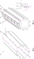
Fig. 5a shows a second embodiment of the food forming drum of the present invention. In this case, each rib 17 comprises at least one, preferably a plurality of recesses 21 which extend all the way through the cross section of the rib and which can be filled at least partially with sintering powder during the manufacturing process. The recesses in the ribs can be produced in a cost-effective manner, for example by laser cutting or water jet cutting or the like. The ribs may extend up to the outer surface of the drum. During unloading, a fluid, for example air, flows between adjacent rows via the recesses 21 provided in each rib 17.
The size and position of the recesses 21 in the ribs should be chosen such that, despite the recesses, the ribs are sufficiently rigid to withstand the pressure during pressing of the porous powder. The recess 21 is only locally provided and does not extend over the entire length of the rib. Preferably, the recess is provided between the two mould cavities, preferably in the middle between the two mould cavities.
The cross-section of the recess 21 in fig. 5b differs from the cross-section of the recess in fig. 5. The shape of the cross-section of the recess according to fig. 5b is advantageous during the manufacturing process and especially during the pressing step, since the forces will be directed such that the sintered powder is forced into the e.g. V-shaped recess. During unloading of the product, the shape of the cross-section of the recess according to fig. 5b also guides the flow of liquid between two adjacent columns of cavities in the direction of the outer circumference of the porous member, thus reducing its effect on the walls of the cavities and the adhesion between the shaped products in the adjacent columns upstream of the column of unloading positions.
Fig. 6a shows a third embodiment of the food forming drum of the present invention. This embodiment is primarily a combination of the embodiments of fig. 4 and 5. During unloading, the fluid is allowed to flow partly through the gap 22 between the outer surface of the drum and the top end of the ribs, i.e. the porous member, and partly through the recesses 21 in the ribs 17. The ratio of flow between the gap 22 and the recess 21 may be selected such that the outer surface of the drum may be deep rolled in a desired manner and/or such that fluid flowing from one column to another will not affect the process of forming the food product. The recess 21 may be designed such that it will direct the fluid to the outer circumference of the porous member as depicted in fig. 5 b.
Fig. 6b shows an alternative to the embodiment according to fig. 6 a. The cost of the ribs 17 can be made more economical in this preferred embodiment. A further advantage is that the recesses created by the porous structure are locked in the longitudinal direction of the drum and the direction of the force during pressing of the porous powder is such that the powder is forced against the top side of the entire rib.
In the embodiment according to fig. 7a, fastening means 33, here fixing strips 33, are used to fasten the porous member to the ribs 17 and/or the inner cylinder, which in this case is preferably the entire cylinder made of porous material. Especially in drum designs where the connection between the porous member and the ribs is not optimal with respect to the forces present during production and cleaning, the porous structure may be connected to the ribs by fixing strips 33. The strip is described as a strip having a rectangular cross section, but is not limited to this shape. This embodiment will preferably be applied in a drum of the porous member 46 having a relatively small height, i.e. its extension in the radial direction. Reference numeral 35 denotes a contact surface between the porous member 46, the rib 17 and the securing means. In this contact area, a sealant is preferably used at least locally to prevent leakage of fluid from one column to an adjacent column during unloading of the shaped product and/or to avoid hygiene problems. The sealant may even be used for contact surfaces not identified with reference numeral 35. The agent may be liquid but gaskets are also possible. In a more preferred embodiment the sealant will be a combination of sealant and adhesive.
In a first embodiment of the manufacturing drum, the ribs 17 will preferably extend beyond the final diameter extension of the drum 2. A porous material will be applied between the ribs. After pressing, sintering and machining the outer circumference, the holes at the outer surface will be closed. In another preferred method of manufacture, the ribs will preferably extend less than the final diameter of the drum. The porous material will be applied beyond the ribs such that an uninterrupted layer of porous material extends over the ribs. After pressing and sintering, the holes at the outer surface of the drum will be closed.
Fig. 7b shows an embodiment in which the rib 17 is provided with one or more recesses 21. This causes a fluid flow, such as a gas or cleaning liquid, to flow between the chambers of adjacent columns. Additionally and/or alternatively, one or more recesses may be provided in the fixing strip 33.
Fig. 8a and b show an embodiment where the porous member 46, preferably a whole cylinder, is fastened to the ribs and/or the inner cylinder 16 by the tensioning means 34. In fig. 8a, the round head screw is provided with a chamfered area acting as a bearing surface against the porous structure and acting as a tensioning device 34. However, other tensioning devices may be used. A recess is provided in the porous member 46 that partially receives the take-up device 34. These recesses are preferably chamfered near the outer surface of the porous member, similar to the support surface of a round head screw. The attachment means 40, in this case a threaded hole, is machined into the outer surface of the tube 16 of a portion of the inner member 24. The location and number of tensioning devices to be used will depend on the forces to be exerted on the porous member during production and/or cleaning. Fig. 8b shows the drum after the outer surface of the drum has been machined. The portion of the take-up device 34 protruding from the outer surface of the porous member is removed resulting in a preferably flat outer surface of the drum while the closed pores on the outer surface of the porous member remain closed.
In the above described embodiments, the porous structure is created by applying the powder in a pre-formed cavity and then by pressing and sintering. However, the porous structure may also be created as a preformed insert to be irreversibly secured to the inner member 16 and/or the ribs 17.
Fig. 9a shows a first embodiment of the food forming drum of the invention with a porous insert 39 in individual segments, each segment being arranged between two ribs 17. During production, the forces exerted on the slug and on the sealing plate 10 will act on each porous insert 39 secured in its position by the ribs 17. During cleaning, a force will be applied into the fluid channel 15 and the insert 39 will be secured in its position by the fixing strip 33.
Possible manufacturing steps for the embodiment of fig. 9a are shown in fig. 9b and 9 c. Fig. 9b-I show the inner member 24 in which the recesses 28 are provided by the inner cylinder 16 and a plurality of ribs 17, preferably welded to the inner cylinder 16. To ensure that the molded products in adjacent columns are fully unloaded only at the unloading position with the same process parameters, such as pressure, the height "hfc" of the fluid passageway 15 should be substantially the same for all columns. Therefore, the positioning accuracy of the ribs with respect to the inner cylinder 16 is important. When the required accuracy cannot be reached by welding, the ribs need to be machined after welding as shown in fig. 9 b-II. The machining is shown in more detail in fig. 9b-III and is denoted by the reference "mr". In a preferred version, the drum 2 includes end caps 26 and 28. These covers may be connected to the inner member by welding or preferably by bolting, before or after the insert is placed in the recess 38. An annular sealing means is preferably provided to prevent leakage of fluid through the end cap connection. The attachment means 40 are preferably provided before, or after, the fixation strips 33 are placed.
The insert 39 may be made in a pre-forming mould or may be made of a porous tube 36 as shown in figure 9 c. The insert is made of the entire cylinder. Preferably first the outer surface of the cylinder will be machined, for example on a lathe and/or grinder, and concentric with an inner diameter "Di" slightly larger than the final diameter of the cylinder, preferably followed by closing the open pores on the outer surface of the porous tube. This ensures a uniform closed layer over the entire surface due to the absence of ribs extending to the outer surface. In order to achieve substantially the same height "hfc" of the fluid channels 15 for each single column, the inner diameter "Di" of the perforated pipe 36 should be obtained according to the desired roundness and cylindricity of the obtained cylinder 2.
For all embodiments described herein, the machining and/or deep rolling of the porous member is preferably performed without using cooling and/or lubricating fluids to prevent these fluids from penetrating into the porous structure.
In a further step, the pipeline is segmented. This can be done in several ways. It is preferred to first provide the recess 37' and the recess 37 "in the porous tube. The drum is still rigid enough to maintain its shape. In a next step, existing bridges between the recesses 37 "are removed in the longitudinal direction of the drum, for example by hand grinding, which results in the separation of the inserts 39. Once the insert does not meet the accuracy required for the height "hfc" of the fluid passageway, the insert requires further processing. Prior to application of the insert 39 into the inner member 24, preferably sealing and/or adhesive means will be used between the ribs and the contacting surfaces of the porous structure.
Fig. 9d-I show a first embodiment of a method of applying an insert irreversibly fixed into the inner member 24. Two inserts 39 will be applied in two adjacent recesses 38 and will be fastened to the inner element by means of the fixing strips 33 and the tensioning means 34 arranged between the inserts. After the first fixing strip is prestressed by the tensioning device, a further insert part is applied and a second fixing strip with the tensioning device is added. This process continues until all inserts are fastened. Fig. 9d-II show a more preferred embodiment, where multiple fixing strips are used on each side of the insert to ensure greater stability in the insert position. In fig. 9d-III, all inserts are fastened to the inner member 24 and fig. 9d-IV shows the drum after the outer surface including the tensioning device 34 has been completely turned over on the lathe and/or grinding machine. The head of the securing device, here a screw, has been removed until it is flush with the outer surface of the porous member. For the outer surface of the drum, only a limited amount of material is removed to maintain a closed outer layer.
The fixing strip 33 is preferably connected to the insert 39 on its left and right hand sides, respectively, preferably over the entire length of the drum to prevent gaps in the outer surface of the porous member. In the method depicted in fig. 9d, the connection height depends on the precision of the machined inner member 24, the insert 39 and the fixing strip 33. In the method described in fig. 9e and 9f, a preferred embodiment is shown, wherein the porous tube 36 may be provided with a smaller recess 37' as can be seen in fig. 9e compared to fig. 9 c. This results in a separate insert 39 which is slightly different in shape from the insert according to fig. 9 c.
Fig. 9f shows an example of how the recess 41 can be milled into the insert after the insert has been placed on the inner member 24 and the insert has not been moved out of its starting position due to shear forces. Fig. 9f-I show a first tool constituting a positioning element 44 and a plurality of bearing blocks 43 to be placed in position for the fixing strips 33. Temporary fixation strips 45 will be used on each side of the insert. By pre-stressing the bearing block and the temporary fixation bar, the insert will be forced against its adjacent rib. In fig. 9f-II the milling of the recess 41 into the insert in the direction of the arrow is shown. The first bearing block in the direction of the arrow has to be removed. The number of bearing blocks to be used depends on whether the insert 39 remains in its position during machining. This method ensures the desired width of the recess 37' over the entire length of the drum. In the embodiment of fig. 9g, the rib 17 is bolted against the inner cylinder 16.
In the embodiment according to fig. 9, the inserts 39 are secured in their position relative to the ribs by means of the geometry of each insert for the forces during production. This requires high precision in machining the outer surfaces of the recess 38 and the insert 39. In order to reduce the dependency on the machining accuracy, the rib 17 in fig. 10a is provided with a shoulder 42 to support the insert 39. Sealing and/or adhesive means may be used on the contact surface 35 but preferably also on the other contact surfaces of the insert 39 and the rib 17.
The dependency of the machining accuracy can be further reduced by machining recesses in the inner surface of the porous insert, so that a support surface is created. Fig. 10a shows this embodiment with the bearing surface of the insert 39 in contact with the shoulder 42. The highest dimensional accuracy can preferably be achieved by machining the recesses of the insert in one setup.
A larger gap between the fixing bar 33 and the rib 17 relative to the embodiment according to fig. 10a is shown in fig. 10 b. The sealant used at the sealing point 35 in this example may be a strip made of food approved material such as plastic or silicone rubber. Preferably the strip is somewhat elastic so that it can counteract the gap during production.
Fig. 11 shows an embodiment in which the dependence of the machining accuracy is further reduced by using a fixing strip 33 having an inclined side wall. In this example, the cross-section of the fixing strip 33 is trapezoidal. However, it may also be, for example, V-shaped. Thus, the insert 39 can be machined within a greater tolerance than in the previous embodiments, which reduces the risk of rejection of the produced insert. A further advantage is that when the fixing strip 33 pre-stresses the insert 39, a seamless mechanical seal will be created, which prevents fluid from leaking out to the outside environment alongside the ribs and the fixing strip. It is also preferred that sealing and/or adhesive means will be used between the ribs and the contact surface of the fixing strip with the insert 39 and preferably also at the other contact surfaces between the insert 39 and the ribs 17. If desired, the exterior surface of the fixation bar may be level with the exterior surface of the porous insert.
The embodiment of fig. 12 shows a different method for manufacturing a drum with irreversibly fixed inserts. The inner member comprises ribs 17 connected to the duct 16. In a next step, the ribs 17 will be shaped according to the method described in connection with fig. 12 a. If the insert 39 is made of a porous tube 36, the pores at the outer surface will be closed before the tube is divided into separate inserts, according to the feasibility regarding the machining precision. In a next step, the insert 39 is shaped according to the embodiment shown in fig. 12. During assembly, the insert 39 will slide into the inner member 24 between the two ribs and then be lifted by the clamping element 32 until the insert is securely fastened against the ribs at the surface contact region "H". Depending on the length of the drum and in order to prevent high assembly forces, a plurality of chamfered clamping elements, preferably with a small angle of inclination and preferably with different heights, may be used. Thus, the contact surface of the insert 39 with the clamping element 32 will be chamfered similar to that described in fig. 12 b. The gripping elements 32 are preferably introduced from the two outer ends of the drum, first the lowest gripping element and then one or more higher elements. It is also preferred that sealing and/or adhesive means will be used between the ribs and the contact surface of the fixing strip with the insert 39 and preferably also between the clamping element and its opposite surface.
According to another preferred or inventive embodiment of the production method, the mould member 2 is made partly or entirely by 3D printing. Depending on the printed material and dimensions, it may be chosen to use printing techniques such as FDM, SLA, SLS, etc.
According to a first preferred embodiment, the entire mould member comprising the fluid channels 15, the porous structure 39 and the closed outer layer is preferably made of food-approved plastic or stainless steel and printed to form a single-part mould member. Depending on the result of the completion, further processing is necessary.
According to a second preferred embodiment, a separate base structure and/or a separate insert with recesses such as inner cylinders and ribs is to be used and the base structure and/or the insert is made of plastic or stainless steel by printing. The base structure and the insert may be printed or made in part (depositing metal on existing structures) or in whole by other manufacturing means as described in WO2012107236 or WO 2014118368. In a next step, the porous insert will be connected to the base structure. The connection between the base structure and the insert is similar to the example in fig. 10 and 11 or one of the other ways described in WO2012107236 or WO 2014118368. As described in WO2012107236 and shown in fig. 28, the porous structure may be printed directly between the recesses of the base structure instead of using separate inserts.
Once the final mold member is not rigid enough to withstand the forces during production and/or cleaning, according to a third preferred embodiment, the mold member may be created by hybrid 3D printing. The plastic primary structure may be reinforced with metal members or the metal may be printed directly on the plastic. In another variant, the metal primary structure will be provided with plastic parts or the plastic may be printed directly on the metal.
Disclaimer of all embodiments:
the invention is not limited to the embodiments shown. Variations of the invention, for example with respect to variations in the position of the mould cavities within the drum in particular, will be possible. Other combinations of tensioning means and/or connecting means than those described in this application are possible. In all of the described embodiments, the porous structure may be applied to the drum either before or after the end caps are attached. In all described embodiments, the sealing layer can be created by deep rolling or by other techniques such as spraying as already described in WO 2012/107236.
List of reference numerals:
1. food product forming equipment
2. Mold member, mold roller, and food molding roller
3. Lump supply system
4. Hopper
5. Feed pump/pump system
6. Material block conveying device
7. Separator
8. Food feeding component
9. Feed channel
10. Sealing device roller, sealing plate
11. Drive side forming equipment
12. Bearing side forming equipment
13. Movable unit
14. Die cavity
15. Fluid channel
16. Internal cylinder, pipe
17. Ribs
18. Permeable support structure
19. Recesses in the ribs 17 accommodating the metal mesh
20. Locking recesses in the ribs 17 of the porous structure
21. Recesses in ribs 17 to allow fluid flow
22. Area/gap above rib 17 to allow fluid flow
23. Butt rib welding connection metal net
24. Inner member
25. First front end of the roller (left side)
26. End cap at front end 25
27. Second front end of the roller (Right side)
28. End cap at front end 27
29. Outer member mold, sintered outer circumference
30. Die set
31. Filling the hole
32. Clamping element
33. Fastening device, fixing strip
34. Tension device
35. Sealing position
36. Porous pipeline
37. Recess in porous tube
38. Recess in a drum accommodating an insert
(partially) porous insert, (partially) porous segment, (partially) porous member
40. Connection device in an inner part 24 for fastening a fastening strip 33
41. Recesses in the drum for receiving the fixing strips 33
42. Shoulder of rib 17
43. Tool: bearing block
44. Tool: positioning element
45. Tool: temporary fixing strip
46. Porous member
47. Chamfer fixing device
48. Top end of rib
Internal diameter of the "Di" porous pipe 36
"H" surface contact area
Height of "hfc" flow channel 15
"mr" processing of ribs 17
Claims (26)
1. A food forming drum (2) comprising an inner member (24) having an inner cylinder (16) and a plurality of ribs (17) extending in a radial direction from the inner cylinder (16) and having at least one porous member (46) made of a porous material with interconnected pores, being connected to the ribs (17) and wherein a plurality of rows of product cavities each comprising one or more product cavities are provided in the porous member, characterized in that the porous member extends radially above the radial extension of the ribs, wherein the food forming drum comprises means connecting the porous member to the inner cylinder (16) and/or the ribs (17), wherein the means extend radially to an outer surface of the porous member,
wherein the device is subsequently partially switched off,
wherein the device comprises a securing means (33), at least partially applying a sealant at the contact surfaces between the porous member (46), the rib (17) and the securing means (33).
2. Food forming drum (2) according to claim 1, characterized in, that the width of each rib cross section is reduced at its top end (48).
3. Food forming drum (2) according to claim 2, characterized in, that each rib (17) comprises at least one recess (21) filled with a porous material.
4. Food forming drum (2) according to claim 3, characterized in, that liquid flows through the recesses during unloading and/or cleaning of the formed food.
5. Food forming drum (2) according to claim 4, characterized in, that the recess (21) guides the liquid to and/or from the outer surface of the porous member (46).
6. Food forming drum (2) according to one of the claims 3-5, characterized in, that the recess (21) is provided at the top end (48) of the rib (17).
7. Food forming drum (2) according to claim 1, characterized in, that it comprises at least one end cover of a material glued to the inner cylinder (16) and/or the ribs (17).
8. Food forming drum (2) according to claim 1, characterized in, that it comprises at least one end cover of material welded to the inner cylinder (16) and/or the ribs (17).
9. Food forming drum (2) according to claim 5, characterized in, that one end cover comprises an opening (31) for filling the inner member with sinter powder.
10. Food forming drum (2) according to claim 6, characterized in, that the means are strips extending over the entire length of the drum.
11. Food forming drum (2) according to claim 10, characterized in, that the strip has a cross section with at least one sloping side wall.
12. Food forming drum (2) according to claim 1, characterized in, that it comprises at least one clamping means (32) clamping the porous member against the ribs.
13. Food forming drum (2) according to claim 1, characterized in, that the porous member is an insert provided with chamfer fixing means (47).
14. Method for producing a food forming drum according to any one of the preceding claims, characterized in that the porous member is fastened to the inner member (24) by means, characterized in that the means are subsequently partly cut off, wherein the means comprise fastening means (33), at least partly with a sealant at the contact surfaces between the porous member (46), the ribs (17) and the fastening means (33).
15. The method of claim 14, wherein the machining and/or deep rolling of the porous member is performed without the use of cooling and/or lubricating fluids.
16. The method of claim 14, wherein a recess is disposed within the porous tube before the porous tube is cut into sections.
17. Method according to claim 14, characterized in that an insert is placed between two ribs (17) and fastened to the inner element (24) by means of a fixing strip (33) and fixing means (34).
18. Method according to claim 17, characterized in that after the placement of the insert on the inner element (24), a recess is machined in the insert.
19. Method according to claim 17, characterized in that the insert slides between two ribs (17) and is then lifted at least partially until it comes into contact with a projection (35) at the rib (17).
20. Method according to claim 14, characterized in that the porous member is sintered, that at least one recess is machined in the porous material and that a fixing strip (33) is arranged in said recess and fixed to the inner member (24) of the food forming drum (2).
21. Method according to claim 20, characterized in that the fixing strip (33) is fastened to the rib (17).
22. Method according to claim 14, characterized in that each porous insert (39) is arranged between two ribs (17) and is fastened to said ribs (17) by means of a fixing strip (33).
23. Method according to claim 22, characterized in that each porous insert (39) is clamped between two ribs (17).
24. Method according to claim 22, characterized in that each porous insert (39) is arranged between two shoulders (42) of two ribs.
25. Method according to claim 22, characterized in that a longitudinal seal (35) is provided between the ribs (17), the porous insert (39) and/or the fixing strip (33).
26. Method according to claim 25, characterized in that the longitudinal seal (35) is a sealing strip.
Applications Claiming Priority (7)
| Application Number | Priority Date | Filing Date | Title |
|---|---|---|---|
| EP14167687 | 2014-05-09 | ||
| EP14167687.4 | 2014-05-09 | ||
| EP14172120 | 2014-06-12 | ||
| EP14172120.9 | 2014-06-12 | ||
| EP14199457.4 | 2014-12-19 | ||
| EP14199457 | 2014-12-19 | ||
| PCT/EP2015/059877 WO2015169812A1 (en) | 2014-05-09 | 2015-05-05 | Design food forming drum |
Publications (2)
| Publication Number | Publication Date |
|---|---|
| CN106455590A CN106455590A (en) | 2017-02-22 |
| CN106455590B true CN106455590B (en) | 2020-10-27 |
Family
ID=53177471
Family Applications (1)
| Application Number | Title | Priority Date | Filing Date |
|---|---|---|---|
| CN201580024048.9A Active CN106455590B (en) | 2014-05-09 | 2015-05-05 | Roller for forming designed food |
Country Status (8)
| Country | Link |
|---|---|
| US (2) | US10238122B2 (en) |
| EP (2) | EP3243389A1 (en) |
| JP (1) | JP6823462B2 (en) |
| CN (1) | CN106455590B (en) |
| BR (1) | BR112016025487A2 (en) |
| CA (1) | CA2946950A1 (en) |
| RU (1) | RU2716225C2 (en) |
| WO (1) | WO2015169812A1 (en) |
Families Citing this family (5)
| Publication number | Priority date | Publication date | Assignee | Title |
|---|---|---|---|---|
| EP3398439A1 (en) * | 2013-02-01 | 2018-11-07 | GEA Food Solutions Bakel B.V. | Food forming drum |
| CA3056401A1 (en) | 2017-04-19 | 2018-10-25 | Gea Food Solutions Bakel B.V. | Improved de-aeration cavities in a mould member |
| PL3706580T3 (en) | 2017-11-07 | 2024-01-22 | Gea Food Solutions Bakel B.V. | Food processing equipment and method with plasma activated water cleaning |
| CA3133052A1 (en) * | 2019-03-26 | 2020-10-01 | Gea Food Solutions Bakel B.V. | Floating particles removal within a food fryer |
| US20220248694A1 (en) | 2019-06-19 | 2022-08-11 | Gea Food Solutions Bakel B.V. | System to Mould Products From a Food Mass |
Family Cites Families (17)
| Publication number | Priority date | Publication date | Assignee | Title |
|---|---|---|---|---|
| US2887964A (en) * | 1956-08-03 | 1959-05-26 | Nat Biscuit Co | Rotary dough-sheet cutters |
| US4276800A (en) * | 1980-04-16 | 1981-07-07 | Nabisco, Inc. | Rotary cutter for scoring dough sheets |
| SU1292694A1 (en) * | 1985-01-17 | 1987-02-28 | Сосисочное Производство Производственного Объединения "Тбилмясо" | Apparatus for moulding dough pieces of articles with filling |
| NL1020942C2 (en) * | 2002-06-26 | 2003-12-30 | Stork Titan Bv | Forming device. |
| RU39448U1 (en) * | 2004-01-19 | 2004-08-10 | Куприй Александр Николаевич | DEVICE FOR MANUFACTURING PRODUCTS FROM A TEST WITH A START, A DOSER OF A START AND A DEVICE FOR FORMING A RELIEF DRAWING ON THE SURFACE OF PRODUCTS FROM A TEST WITH A START |
| NL1026171C2 (en) * | 2004-05-11 | 2005-11-14 | Stork Titan Bv | To shape. |
| US7931461B2 (en) * | 2007-11-28 | 2011-04-26 | Stork Titan B.V. | Mould member for moulding three-dimensional products, system and methods of manufacturing a mould member |
| US8622730B2 (en) * | 2008-12-23 | 2014-01-07 | General Mills, Inc. | Dough forming and cutting apparatus and method |
| US8622729B2 (en) * | 2008-12-23 | 2014-01-07 | General Mills, Inc. | Dough cutting and stamping apparatus and method |
| NL2003185C2 (en) * | 2009-07-10 | 2011-01-11 | Stork Titan Bv | Moulding device, moulding element, moulding method, food preparation method and moulded product. |
| PL2449893T3 (en) * | 2010-11-04 | 2017-09-29 | Gea Food Solutions Bakel B.V. | Mass distribution device and molding device |
| JP5993381B2 (en) * | 2011-02-10 | 2016-09-14 | ジーイーエー フード ソリューションズ バーケル ビー.ブイ. | Food molding drum |
| US9554593B2 (en) * | 2011-07-25 | 2017-01-31 | Gea Food Solutions Bakel B.V. | Food forming apparatus with a food feed member |
| US9044025B2 (en) * | 2013-06-13 | 2015-06-02 | Michel T Bakhoum | Apparatus and method for simultaneous cutting, imprinting and piercing of dough |
| EP3398439A1 (en) | 2013-02-01 | 2018-11-07 | GEA Food Solutions Bakel B.V. | Food forming drum |
| NL2013121B1 (en) * | 2014-07-04 | 2016-09-20 | Marel Townsend Further Proc Bv | Method for producing a cylindrical mould member for moulding three-dimensional products from a mass of one or more food starting materials. |
| US9844889B1 (en) * | 2015-09-14 | 2017-12-19 | Weidenmiller Company | Rotary tool ejection technology |
-
2015
- 2015-05-05 BR BR112016025487A patent/BR112016025487A2/en not_active Application Discontinuation
- 2015-05-05 EP EP17177897.0A patent/EP3243389A1/en active Pending
- 2015-05-05 WO PCT/EP2015/059877 patent/WO2015169812A1/en active Application Filing
- 2015-05-05 US US15/304,949 patent/US10238122B2/en active Active
- 2015-05-05 RU RU2016148220A patent/RU2716225C2/en active
- 2015-05-05 CN CN201580024048.9A patent/CN106455590B/en active Active
- 2015-05-05 CA CA2946950A patent/CA2946950A1/en not_active Abandoned
- 2015-05-05 EP EP15722504.6A patent/EP3139751A1/en not_active Withdrawn
- 2015-05-05 JP JP2016566919A patent/JP6823462B2/en active Active
-
2019
- 2019-01-28 US US16/259,347 patent/US10856555B2/en active Active
Also Published As
| Publication number | Publication date |
|---|---|
| JP2017518742A (en) | 2017-07-13 |
| US10238122B2 (en) | 2019-03-26 |
| US20190166854A1 (en) | 2019-06-06 |
| BR112016025487A2 (en) | 2017-08-15 |
| EP3139751A1 (en) | 2017-03-15 |
| RU2016148220A3 (en) | 2018-11-19 |
| WO2015169812A1 (en) | 2015-11-12 |
| RU2016148220A (en) | 2018-06-09 |
| US10856555B2 (en) | 2020-12-08 |
| JP6823462B2 (en) | 2021-02-03 |
| EP3243389A1 (en) | 2017-11-15 |
| CA2946950A1 (en) | 2015-11-12 |
| US20170142987A1 (en) | 2017-05-25 |
| CN106455590A (en) | 2017-02-22 |
| RU2716225C2 (en) | 2020-03-06 |
Similar Documents
| Publication | Publication Date | Title |
|---|---|---|
| CN106455590B (en) | Roller for forming designed food | |
| EP2064956B1 (en) | Mould member for moulding three-dimensional products, system and methods of manufacturing a mould member | |
| US8029266B2 (en) | Mould member for moulding three-dimensional products, system and methods of manufacturing a mould member | |
| CN103501620B (en) | Food forming cylinder | |
| CN103188953B (en) | Material dispenser apparatus and device for molding | |
| US20210092962A1 (en) | Food forming concept | |
| JP2014522657A (en) | Food molding apparatus provided with a food lump supply member | |
| US9737080B2 (en) | Moulding device, and method for moulding food products | |
| CN106256517A (en) | The screw feeder of concrete mix and the manufacture method of screw feeder |
Legal Events
| Date | Code | Title | Description |
|---|---|---|---|
| C06 | Publication | ||
| PB01 | Publication | ||
| SE01 | Entry into force of request for substantive examination | ||
| SE01 | Entry into force of request for substantive examination | ||
| GR01 | Patent grant | ||
| GR01 | Patent grant |