CN106369603B - Secondary upper air inlet burner - Google Patents
Secondary upper air inlet burner Download PDFInfo
- Publication number
- CN106369603B CN106369603B CN201610947405.5A CN201610947405A CN106369603B CN 106369603 B CN106369603 B CN 106369603B CN 201610947405 A CN201610947405 A CN 201610947405A CN 106369603 B CN106369603 B CN 106369603B
- Authority
- CN
- China
- Prior art keywords
- air inlet
- inlet nozzle
- injection pipe
- annular groove
- support
- Prior art date
- Legal status (The legal status is an assumption and is not a legal conclusion. Google has not performed a legal analysis and makes no representation as to the accuracy of the status listed.)
- Active
Links
Images


Classifications
-
- F—MECHANICAL ENGINEERING; LIGHTING; HEATING; WEAPONS; BLASTING
- F23—COMBUSTION APPARATUS; COMBUSTION PROCESSES
- F23D—BURNERS
- F23D14/00—Burners for combustion of a gas, e.g. of a gas stored under pressure as a liquid
- F23D14/02—Premix gas burners, i.e. in which gaseous fuel is mixed with combustion air upstream of the combustion zone
- F23D14/04—Premix gas burners, i.e. in which gaseous fuel is mixed with combustion air upstream of the combustion zone induction type, e.g. Bunsen burner
-
- F—MECHANICAL ENGINEERING; LIGHTING; HEATING; WEAPONS; BLASTING
- F23—COMBUSTION APPARATUS; COMBUSTION PROCESSES
- F23D—BURNERS
- F23D14/00—Burners for combustion of a gas, e.g. of a gas stored under pressure as a liquid
- F23D14/46—Details, e.g. noise reduction means
-
- F—MECHANICAL ENGINEERING; LIGHTING; HEATING; WEAPONS; BLASTING
- F23—COMBUSTION APPARATUS; COMBUSTION PROCESSES
- F23D—BURNERS
- F23D14/00—Burners for combustion of a gas, e.g. of a gas stored under pressure as a liquid
- F23D14/46—Details, e.g. noise reduction means
- F23D14/62—Mixing devices; Mixing tubes
- F23D14/64—Mixing devices; Mixing tubes with injectors
-
- F—MECHANICAL ENGINEERING; LIGHTING; HEATING; WEAPONS; BLASTING
- F23—COMBUSTION APPARATUS; COMBUSTION PROCESSES
- F23D—BURNERS
- F23D14/00—Burners for combustion of a gas, e.g. of a gas stored under pressure as a liquid
- F23D14/46—Details, e.g. noise reduction means
- F23D14/72—Safety devices, e.g. operative in case of failure of gas supply
- F23D14/725—Protection against flame failure by using flame detection devices
-
- F—MECHANICAL ENGINEERING; LIGHTING; HEATING; WEAPONS; BLASTING
- F23—COMBUSTION APPARATUS; COMBUSTION PROCESSES
- F23D—BURNERS
- F23D2203/00—Gaseous fuel burners
- F23D2203/007—Mixing tubes, air supply regulation
Abstract
The invention discloses a secondary upper air inlet burner which comprises a base and a support, wherein the base and the support are integrally formed, the support is arranged on the base, a primary air inlet is arranged between the base and the support, a thermocouple is arranged on the base, and an outer layer air inlet nozzle and an inner layer air inlet nozzle are obliquely arranged on the base; the bracket is obliquely provided with an outer layer injection pipe and an inner layer injection pipe; the bracket is provided with an outer annular groove, a middle annular groove and an inner annular groove, the outer annular groove is communicated with the outer air inlet nozzle through an outer layer injection pipe, and the inner annular groove is communicated with the inner air inlet nozzle through an inner layer injection pipe; the bracket is provided with a secondary air inlet communicated with the middle annular groove. The secondary upper air inlet burner has the advantages of large air inlet amount, long injection pipeline, uniform mixing of gas and air, full combustion, and prevention of gas leakage due to the arrangement of the thermocouple on the base. And the base and the bracket are integrally formed, so that the manufacturing and the assembly are simple and convenient.
Description
Technical Field
The invention relates to the field of cookers, in particular to a secondary upper air inlet burner.
Background
The existing gas cooker generally adopts an upper air inlet burner, and the working principle is as follows: the gas draws the ejector tube from the admission nozzle entering with certain velocity of flow under certain pressure, relies on the ejection effect of gas energy own, attracts a certain amount of air around, and this part of air is called "primary air", and primary air and gas are drawing the ejector tube and mix the back and are burning, draws the air combustion-supporting around the flame in the combustion process, and this part of air is called "secondary air", however the air intake is not enough can lead to the burning insufficient, and air and gas mix inhomogeneous can lead to combustion efficiency not high.
Chinese patent (application No. 201120315395.6) discloses an upper air inlet burner, which is provided with an inner burning plate and an outer burning plate, wherein the inner burning plate and the outer burning plate are both provided with side air inlets, the inner burning plate is fixed on the outer burning plate, and outside air enters the inner burning plate through the side air inlets for supporting combustion. Although this go up air inlet burner air input is sufficient, the admission nozzle of this combustor is vertical setting, forms great contained angle with the horizontal plane, so draw with the same of admission nozzle the central axis and penetrate the pipe just unable extension for draw and penetrate the effect poor, the gas is not abundant also inhomogeneous with the air mixing, leads to combustion efficiency to hang down, does not have protection device moreover, and when the combustor extinguishes suddenly, coal gas easily reveals, and this outer combustor has a plurality of parts, makes the manufacturing assembly complicated.
Disclosure of Invention
Aiming at the defects of the prior art, the secondary upper air inlet burner is provided, an injection pipe is obliquely arranged on the burner, so that the injection pipeline is lengthened, and an inner layer-shaped groove and an outer layer-shaped groove are further arranged, so that gas and air are mixed in a rotating flow manner and are fully and uniformly mixed; set up the opening on the support, increased the air input, the gas can the abundant burning. And be provided with flame-out protection device on the base, prevent that the gas from revealing, base and support are integrated into one piece, make the assembly simple.
In order to achieve the above object, the present invention provides the following technical solutions.
A secondary upper air inlet burner comprises a base and a support, wherein the support is arranged on the base, a first outer layer air inlet nozzle, a first inner layer air inlet nozzle, a second outer layer air inlet nozzle and a second inner layer air inlet nozzle are obliquely arranged on the base, a first outer layer injection pipe corresponding to the first outer layer air inlet nozzle, a first inner layer injection pipe corresponding to the first inner layer air inlet nozzle, a second outer layer injection pipe corresponding to the second outer layer air inlet nozzle and a second inner layer injection pipe corresponding to the second inner layer air inlet nozzle are obliquely arranged on the support, the first outer layer injection pipe and the second outer layer injection pipe are arranged in a centrosymmetric mode, and the first inner layer injection pipe and the second inner layer injection pipe are arranged in a centrosymmetric mode; a primary air inlet communicated with the first outer-layer injection pipe, the second outer-layer injection pipe, the first inner-layer injection pipe and the second inner-layer injection pipe is arranged between the base and the support; the support is provided with an outer-layer annular groove, and the outer-layer annular groove is communicated with a first outer-layer air inlet nozzle through a first outer-layer injection pipe and is communicated with a second outer-layer air inlet nozzle through a second outer-layer injection pipe; the support is provided with an inner annular groove, and the inner annular groove is communicated with a first inner air inlet nozzle through a first inner injection pipe and is communicated with a second inner air inlet nozzle through a second inner injection pipe; the middle of the bracket is provided with a middle annular groove, and the bracket is provided with a secondary air inlet communicated with the middle annular groove.
Furthermore, the upper end surface of the outer annular groove is higher than that of the inner annular groove.
Furthermore, the first outer layer air inlet nozzle and the second outer layer air inlet nozzle are communicated through a butt joint pipe arranged at the upper end of the base, and the first inner layer air inlet nozzle and the second inner layer air inlet nozzle are communicated through a butt joint pipe arranged at the lower end of the base.
Further, the base and the support are respectively integrally formed.
Furthermore, an ignition needle and a thermocouple are arranged on the base, a first mounting hole for mounting the ignition needle and a second mounting hole for mounting the thermocouple are arranged on the support, and an air inlet is further formed in the support.
Furthermore, a plurality of supporting columns of the supporting bracket are arranged on the base, the primary air inlet is formed between two adjacent supporting columns, a plurality of supporting columns are arranged on the lower end face of the base, and the water receiving disc is sleeved on the base.
Furthermore, a clamping groove is arranged on the support, and a corresponding buckle is arranged on the support.
Furthermore, adjusting nuts are respectively arranged on the first outer layer air inlet nozzle, the first inner layer air inlet nozzle, the second outer layer air inlet nozzle and the second inner layer air inlet nozzle.
Furthermore, copper rings are respectively embedded on the upper end faces of the annular groove on the outer layer and the annular groove on the inner layer of the bracket.
Furthermore, a central air inlet channel is arranged at the center of the support, and a middle air inlet channel is arranged in the middle annular groove.
The invention has the beneficial effects that: a secondary upper air inlet burner comprises a base and a support, wherein an injection pipe is obliquely arranged on the support to lengthen an injection pipeline, the support is also provided with an inner-layer annular groove and an outer-layer annular groove, after gas enters the inner-layer annular groove and the outer-layer annular groove through the injection pipe, air and the gas flow along the circumferences of the inner-layer annular groove and the outer-layer annular groove, and the gas and the air are mixed in a rotating flow manner and are fully and uniformly mixed; set up the opening on the support and the support is provided with the air inlet, has increased air intake volume, and the gas can fully burn and combustion efficiency is high. In addition, the flame-out protection device is arranged on the base, gas leakage is prevented, the base and the support are respectively integrally formed, and manufacturing and assembling are simple.
Drawings
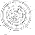
Fig. 1 is a schematic structural view of the present invention.
Fig. 2 is a schematic view of an exploded structure of the present invention.
Fig. 3 is a schematic view of the base structure of the present invention.
Fig. 4 is a schematic view (bottom view) of the base structure of the present invention.
FIG. 5 is a schematic view of the stent structure of the present invention.
Fig. 6 is a schematic view (bottom view) of the inventive stent structure.
Fig. 7 is a schematic structural view of a stent according to another embodiment of the present invention.
Fig. 8 is a schematic structural view (bottom view) of a stand according to another embodiment of the present invention.
In the figure, 1, a base; 10; a primary air inlet; 11. a first outer layer inlet nozzle; 12. a first inner layer air inlet nozzle; 13. butt-joint pipes; 14. a support pillar; 15. a pillar; 16. a second outer layer air inlet nozzle; 17. a second inner layer air inlet nozzle; 18. a thermocouple; 19. an ignition needle; 2. a support; 20. a secondary air inlet; 21. a first outer injection pipe; 22. a first inner-layer ejector tube; 23. an outer annular groove; 24. a middle annular groove; 25. an inner annular groove; 26. a second outer layer injection pipe; 27. a second inner-layer ejector pipe; 28. buckling; 29. a first mounting hole; 30. an air inlet; 31 a second mounting hole; 32. a central air intake passage; 33. an intermediate intake passage.
Detailed Description
The invention is further explained with reference to the drawings.
Referring to fig. 1 to 6, the secondary upper air inlet burner includes a base 1 and a bracket 2, the base 1 is provided with four supporting pillars 15 for supporting the bracket 2, a primary air inlet 10 is formed between two adjacent supporting pillars 15, the base 1 and the bracket 2 are connected through the supporting pillars 15, so that a contact area between the base 1 and the bracket 2 is reduced, and heat conducted from the bracket 2 to the base 1 when the burner works is reduced. A clamping groove is formed in each strut 15, four buckles 28 are correspondingly arranged on the support 2, and the buckles 28 are tightly matched with the clamping grooves to prevent the support 2 and the base 1 from rotating relatively.
The base 1 is obliquely provided with a first outer layer air inlet nozzle 11, a first inner layer air inlet nozzle 12, a second outer layer air inlet nozzle 16 and a second inner layer air inlet nozzle 17, the support 2 is obliquely provided with a first outer layer injection pipe 21 corresponding to the first outer layer air inlet nozzle 11, a first inner layer injection pipe 22 corresponding to the first inner layer air inlet nozzle 12, a second outer layer injection pipe 26 corresponding to the second outer layer air inlet nozzle 16 and a second inner layer injection pipe 27 corresponding to the second inner layer air inlet nozzle 17, the first outer layer injection pipe 21 and the second outer layer injection pipe 26 are arranged in a central symmetry mode, and the first inner layer injection pipe 22 and the second inner layer injection pipe 27 are arranged in a central symmetry mode.
The bracket 2 is provided with an outer annular groove 23, and the outer annular groove 23 is communicated with the first outer air inlet nozzle 11 through a first outer injection pipe 21 and communicated with the second outer air inlet nozzle 16 through a second outer injection pipe 26; the first outer layer air inlet nozzle 11 and the second outer layer air inlet nozzle 16 are respectively connected with an adjusting nut through threads, and the gap between the air inlet nozzle and the injection pipe can be adjusted through the adjusting nut, so that the adjustment of the air inflow of initial air is facilitated, and a proper amount of air is mixed when the fuel gas is injected into the injection pipe.
The support 2 is provided with an inner annular groove 25, and the inner annular groove 25 is communicated with the first inner air inlet nozzle 12 through a first inner injection pipe 22 and communicated with the second inner air inlet nozzle 17 through a second inner injection pipe 27; the first inner layer air inlet nozzle 12 and the second inner layer air inlet nozzle 17 are respectively connected with an adjusting nut through threads, and the gap between the air inlet nozzle and the injection pipe can be adjusted through the adjusting nut, so that the adjustment of the air inflow of initial air is facilitated, and a proper amount of air is mixed when the fuel gas is injected into the injection pipe.
The support 2 is provided with a middle annular groove 24, and the support 2 is provided with a secondary air inlet 20 communicated with the middle annular groove 24. The heights of the upper end faces of the outer annular groove 23, the middle annular groove 24 and the inner annular groove 25 are sequentially reduced, air can enter the middle annular groove 24 through the secondary air inlet 20, the air in the middle annular groove 24 can be supplemented to the inner annular groove 25, and therefore the air in the inner annular groove 25 is sufficient and the combustion is more sufficient. The bracket 2 is also provided with an air inlet 30 communicated with the inner annular groove 25, and air enters the inner annular groove 25 through the air inlet 30 to be fully mixed with fuel gas.
The base 1 is provided with a first positioning column and a second positioning column, the support 2 is provided with a first mounting hole 29 for mounting the first positioning column and a second mounting hole 31 for mounting the second positioning column, and the first positioning column and the second positioning column have a positioning effect when the support 2 and the base 1 are mounted. An ignition needle 19 is arranged in the first positioning column, a thermocouple 18 is arranged in the second positioning column, and the thermocouple 18 can rapidly cut off fuel gas after flame is extinguished outside the flame, so that the fuel gas is prevented from leaking.
The terminal surface is provided with three support column 14 under the base 1, and the combustor is convenient for place by three support column 14, and three support column 14 is installed in the top of a kitchen range moreover, has reduced the area of contact of combustor with the top of a kitchen range to conduction to the inside heat of top of a kitchen range has been reduced on the combustor base 1 of during operation. The base 1 is sleeved with a water receiving disc, so that when the cooking bench is prevented from leaking water, water enters the combustor, and the combustor is prevented from being broken down.
First outer air inlet nozzle 11 and second outer air inlet nozzle 16 are through setting up the butt joint pipe 13 intercommunication in base 1 upper end, first inlayer air inlet nozzle 12 and second inlayer air inlet nozzle 17 are through setting up the butt joint pipe 13 intercommunication at base 1 lower extreme, when the gas gets into from first outer air inlet nozzle 11 and first inlayer air inlet nozzle 12, partial gas accessible gets into second outer air inlet nozzle 16 and second inlayer air inlet nozzle 17 to butt joint pipe 13, in the combustor during operation, only need let in the gas to first outer air inlet nozzle 11 and first inlayer air inlet nozzle 12, alright guarantee that four air inlet nozzles all have the gas blowout.
Furthermore, copper rings are respectively embedded on the upper end faces of the outer layer annular groove 23 and the inner layer annular groove 25 of the support 2, so that the combustor is prevented from deforming under the working environment of long-term high-temperature combustion. The base 1 and the support 2 are respectively integrally formed, so that the burner is simpler and more convenient to manufacture and assemble.
Referring to fig. 7 and 8, another embodiment of the present invention is different from the previous embodiment in that a central air inlet channel 32 is provided in the center of the support 2, air can be mixed with the fuel gas in the inner annular groove 25 through the central air inlet channel 32, a middle air inlet channel 33 is provided in the middle annular groove 24, air can enter the middle annular groove through the middle air inlet channel 33, and the air in the middle annular groove 24 can be supplemented to the inner annular groove 25, so that the air in the inner annular groove 25 is sufficient, and the combustion is more sufficient.
The above description is only a preferred embodiment of the present invention, and all equivalent changes or modifications of the structure, characteristics and principles described in the present invention are included in the scope of the present invention.
Claims (4)
1. The utility model provides a combustor of intaking on secondary, includes base (1) and support (2), and support (2) set up on base (1), its characterized in that: the base (1) is obliquely provided with a first outer layer air inlet nozzle (11), a first inner layer air inlet nozzle (12), a second outer layer air inlet nozzle (16) and a second inner layer air inlet nozzle (17), the support (2) is obliquely provided with a first outer layer injection pipe (21) corresponding to the first outer layer air inlet nozzle (11), a first inner layer injection pipe (22) corresponding to the first inner layer air inlet nozzle (12), a second outer layer injection pipe (26) corresponding to the second outer layer air inlet nozzle (16) and a second inner layer injection pipe (27) corresponding to the second inner layer air inlet nozzle (17), the first outer layer injection pipe (21) and the second outer layer injection pipe (26) are arranged in a centrosymmetric manner, and the first inner layer injection pipe (22) and the second inner layer injection pipe (27) are arranged in a centrosymmetric manner; a primary air inlet (10) communicated with the first outer-layer injection pipe (21), the second outer-layer injection pipe (26), the first inner-layer injection pipe (22) and the second inner-layer injection pipe (27) is arranged between the base (1) and the support (2); the support (2) is provided with an outer annular groove (23), and the outer annular groove (23) is communicated with the first outer air inlet nozzle (11) through a first outer injection pipe (21) and communicated with the second outer air inlet nozzle (16) through a second outer injection pipe (26); the support (2) is provided with an inner annular groove (25), and the inner annular groove (25) is communicated with the first inner air inlet nozzle (12) through a first inner injection pipe (22) and communicated with the second inner air inlet nozzle (17) through a second inner injection pipe (27); a middle annular groove (24) is formed in the middle of the support (2), a secondary air inlet (20) communicated with the middle annular groove (24) is formed in the support (2), and the base (1) and the support (2) are integrally formed respectively;
the upper end surface of the outer layer annular groove (23) is higher than the upper end surface of the inner layer annular groove (25); the first outer layer air inlet nozzle (11) and the second outer layer air inlet nozzle (16) are communicated through a butt joint pipe (13) arranged at the upper end of the base (1), and the first inner layer air inlet nozzle (12) and the second inner layer air inlet nozzle (17) are communicated through the butt joint pipe (13) arranged at the lower end of the base (1); an ignition needle (19) and a thermocouple (18) are arranged on the base (1), a first mounting hole (29) for mounting the ignition needle (19) and a second mounting hole (31) for mounting the thermocouple are arranged on the support (2), and an air inlet (30) is further arranged on the support (2); the base (1) is provided with a plurality of pillars (15) for supporting the bracket (2), the primary air inlet (10) is formed between two adjacent pillars (15), the lower end surface of the base (1) is provided with a plurality of supporting columns (14), and the base (1) is sleeved with a water receiving disc; a central air inlet channel (32) is arranged in the center of the support (2), and a middle air inlet channel (33) is arranged in the middle annular groove (24); the outer layer annular groove (23) and the inner layer annular groove (25) are both open; the injection pipes are directly formed at the bottom of the bracket and are of an integrally formed structure with the bracket; the air inlet nozzle is directly communicated with the corresponding injection pipe, and the central axis of the air inlet nozzle and the central axis of the injection pipe are arranged in a mode of inclining upwards with the plane of the base (1).
2. The overfire air burner of claim 1, wherein: the support (15) is provided with a clamping groove, and the support (2) is provided with a corresponding buckle (28).
3. The overfire air burner of claim 1, wherein: and the first outer layer air inlet nozzle (11), the first inner layer air inlet nozzle (12), the second outer layer air inlet nozzle (16) and the second inner layer air inlet nozzle (17) are respectively provided with an adjusting nut.
4. The overfire air burner of claim 1, wherein: copper rings are respectively embedded in the upper end faces of the outer annular groove (23) and the inner annular groove (25) of the support (2).
Priority Applications (1)
| Application Number | Priority Date | Filing Date | Title |
|---|---|---|---|
| CN201610947405.5A CN106369603B (en) | 2016-10-26 | 2016-10-26 | Secondary upper air inlet burner |
Applications Claiming Priority (1)
| Application Number | Priority Date | Filing Date | Title |
|---|---|---|---|
| CN201610947405.5A CN106369603B (en) | 2016-10-26 | 2016-10-26 | Secondary upper air inlet burner |
Publications (2)
| Publication Number | Publication Date |
|---|---|
| CN106369603A CN106369603A (en) | 2017-02-01 |
| CN106369603B true CN106369603B (en) | 2021-12-17 |
Family
ID=57894238
Family Applications (1)
| Application Number | Title | Priority Date | Filing Date |
|---|---|---|---|
| CN201610947405.5A Active CN106369603B (en) | 2016-10-26 | 2016-10-26 | Secondary upper air inlet burner |
Country Status (1)
| Country | Link |
|---|---|
| CN (1) | CN106369603B (en) |
Families Citing this family (4)
| Publication number | Priority date | Publication date | Assignee | Title |
|---|---|---|---|---|
| CN108758630A (en) * | 2018-07-16 | 2018-11-06 | 宁波风腾燃具有限公司 | A kind of upper inlet wind type burner |
| WO2020047937A1 (en) * | 2018-09-04 | 2020-03-12 | 佛山市顺德区美的洗涤电器制造有限公司 | Burner and cooker |
| CN109000242B (en) * | 2018-09-04 | 2021-02-26 | 佛山市顺德区美的洗涤电器制造有限公司 | Burner with a burner head |
| CN116164281A (en) * | 2023-03-13 | 2023-05-26 | 宁波风腾燃具有限公司 | Improved upper air inlet burner |
Family Cites Families (12)
| Publication number | Priority date | Publication date | Assignee | Title |
|---|---|---|---|---|
| CN200996603Y (en) * | 2007-01-11 | 2007-12-26 | 广东万和集团有限公司 | Burner of gas cooker with upper air-intake function |
| CN101089468A (en) * | 2007-05-25 | 2007-12-19 | 江苏光芒燃具股份有限公司 | High energy, whole oxygen supply, three-gas compatible burner |
| CN201327032Y (en) * | 2008-11-20 | 2009-10-14 | 江苏光芒燃具股份有限公司 | Precision alloy three-gas compatible burner capable of being adjusted without air valve |
| CN201858642U (en) * | 2010-10-27 | 2011-06-08 | 中山市樱雪集团有限公司 | Full-upside air inlet type stove burner |
| CN201935191U (en) * | 2011-01-21 | 2011-08-17 | 佛山市顺德区日野电气有限公司 | Pure upper wind inlet large heat flow burner |
| CN202216246U (en) * | 2011-08-26 | 2012-05-09 | 吕一宁 | Upper air-inlet burner |
| CN202392799U (en) * | 2011-12-16 | 2012-08-22 | 中山万和电器有限公司 | Complete upper air inlet stove combustor |
| CN103994436B (en) * | 2014-05-19 | 2017-04-12 | 宁波方太厨具有限公司 | Upper air inlet type burner for gas stove |
| CN204534589U (en) * | 2015-01-23 | 2015-08-05 | 俞国平 | The upper air inlet distributor of embedded gas range |
| CN105090958A (en) * | 2015-08-04 | 2015-11-25 | 嵊州市杰太电器有限公司 | Pure upper inlet air type pressure stabilization burner for gas stove |
| CN105351929A (en) * | 2015-12-08 | 2016-02-24 | 宁波风腾燃具有限公司 | Upside-entrainment burner |
| CN206269135U (en) * | 2016-10-26 | 2017-06-20 | 宁波风腾燃具有限公司 | Secondary upper inlet wind type burner |
-
2016
- 2016-10-26 CN CN201610947405.5A patent/CN106369603B/en active Active
Also Published As
| Publication number | Publication date |
|---|---|
| CN106369603A (en) | 2017-02-01 |
Similar Documents
| Publication | Publication Date | Title |
|---|---|---|
| CN106369603B (en) | Secondary upper air inlet burner | |
| CN207049921U (en) | A kind of burner of gas-cooker | |
| CN202733890U (en) | Stove burner using blast type to supplement secondary air | |
| CN206257666U (en) | A kind of adjustable upper inlet wind type burner | |
| JP5613186B2 (en) | Comrobana | |
| CN208871618U (en) | Furnace combustor | |
| CN203364130U (en) | Combustor | |
| CN110631011A (en) | Tertiary air mixing gas combustion device | |
| CN201672516U (en) | Oven burner | |
| CN206269135U (en) | Secondary upper inlet wind type burner | |
| CN106765093B (en) | A kind of burner | |
| CN103047648A (en) | Differential power combustor of gas cooker | |
| CN202675375U (en) | Infrared energy gathering combustor | |
| CN209042368U (en) | A kind of burner | |
| CN111256126B (en) | Burner for gas stove | |
| CN106705038B (en) | A kind of integral type is entirely into wind combustor | |
| CN104180371A (en) | Combustor | |
| CN206430108U (en) | A kind of integral type enters wind combustor entirely | |
| CN111256125B (en) | Burner for gas stove | |
| CN206669742U (en) | A kind of burner throttle adjusting means | |
| CN204268471U (en) | Burner | |
| CN206257702U (en) | Upper inlet wind type burner | |
| CN202757125U (en) | Flocculating-flow burning disk of gas burner | |
| CN208186429U (en) | A kind of waterproof upper inlet wind type burner | |
| CN207849368U (en) | A kind of fire cover cover board and the burner with the fire cover cover board |
Legal Events
| Date | Code | Title | Description |
|---|---|---|---|
| C06 | Publication | ||
| PB01 | Publication | ||
| SE01 | Entry into force of request for substantive examination | ||
| SE01 | Entry into force of request for substantive examination | ||
| GR01 | Patent grant | ||
| GR01 | Patent grant |