CN106340407B - Contact bridge arrangement for an electrical switching element - Google Patents
Contact bridge arrangement for an electrical switching element Download PDFInfo
- Publication number
- CN106340407B CN106340407B CN201610532246.2A CN201610532246A CN106340407B CN 106340407 B CN106340407 B CN 106340407B CN 201610532246 A CN201610532246 A CN 201610532246A CN 106340407 B CN106340407 B CN 106340407B
- Authority
- CN
- China
- Prior art keywords
- contact bridge
- stop
- actuation
- bridge arrangement
- contact
- Prior art date
- Legal status (The legal status is an assumption and is not a legal conclusion. Google has not performed a legal analysis and makes no representation as to the accuracy of the status listed.)
- Expired - Fee Related
Links
Images


Classifications
-
- H—ELECTRICITY
- H01—ELECTRIC ELEMENTS
- H01H—ELECTRIC SWITCHES; RELAYS; SELECTORS; EMERGENCY PROTECTIVE DEVICES
- H01H1/00—Contacts
- H01H1/12—Contacts characterised by the manner in which co-operating contacts engage
- H01H1/14—Contacts characterised by the manner in which co-operating contacts engage by abutting
- H01H1/20—Bridging contacts
- H01H1/2008—Facilitate mounting or replacing contact bridge and pressure spring on carrier
-
- H—ELECTRICITY
- H01—ELECTRIC ELEMENTS
- H01H—ELECTRIC SWITCHES; RELAYS; SELECTORS; EMERGENCY PROTECTIVE DEVICES
- H01H1/00—Contacts
- H01H1/12—Contacts characterised by the manner in which co-operating contacts engage
- H01H1/14—Contacts characterised by the manner in which co-operating contacts engage by abutting
- H01H1/24—Contacts characterised by the manner in which co-operating contacts engage by abutting with resilient mounting
- H01H1/26—Contacts characterised by the manner in which co-operating contacts engage by abutting with resilient mounting with spring blade support
-
- H—ELECTRICITY
- H01—ELECTRIC ELEMENTS
- H01H—ELECTRIC SWITCHES; RELAYS; SELECTORS; EMERGENCY PROTECTIVE DEVICES
- H01H50/00—Details of electromagnetic relays
- H01H50/54—Contact arrangements
- H01H50/546—Contact arrangements for contactors having bridging contacts
-
- H—ELECTRICITY
- H01—ELECTRIC ELEMENTS
- H01H—ELECTRIC SWITCHES; RELAYS; SELECTORS; EMERGENCY PROTECTIVE DEVICES
- H01H50/00—Details of electromagnetic relays
- H01H50/54—Contact arrangements
- H01H50/56—Contact spring sets
Landscapes
- Physics & Mathematics (AREA)
- Electromagnetism (AREA)
- Push-Button Switches (AREA)
- Seats For Vehicles (AREA)
- Coupling Device And Connection With Printed Circuit (AREA)
Abstract
一种触桥布置(1),用于诸如接触器或继电器的电气开关元件,具有触桥(3);致动构件(5),触桥(3)沿致动方向(B)以可移动的方式被保持在致动构件上;至少一个弹簧元件(7),插入到致动构件上的弹簧基座(53)和触桥(3)之间;以及至少一个止动件(9),触桥(3)被至少一个弹簧元件(7)按压抵靠止动件。根据本发明,为了提供具有更小的总尺寸、稳定、快速且易于组装的触桥布置,意图为使得至少一个止动件(9)和弹簧基座(53)位于至少一个弹簧元件(7)的背离触桥(3)的侧面(83)上。
A contact bridge arrangement (1) for an electrical switching element such as a contactor or a relay, having a contact bridge (3); an actuating member (5), the contact bridge (3) being movable in an actuation direction (B) is held on the actuating member in a manner; at least one spring element (7), inserted between the spring base (53) and the contact bridge (3) on the actuating member; and at least one stop (9), The contact bridge (3) is pressed against the stop by at least one spring element (7). According to the invention, in order to provide a contact bridge arrangement with smaller overall dimensions, stable, fast and easy to assemble, it is intended that the at least one stop (9) and the spring base (53) are located on the at least one spring element (7) on the side (83) facing away from the contact bridge (3).
Description
技术领域technical field
本发明涉及一种触桥布置(contact bridge arrangement),用于诸如接触器或继电器的电气开关元件,所述触桥布置具有触桥;致动构件,所述触桥沿致动方向以可移动的方式被保持在所述致动构件上;至少一个弹簧元件,所述弹簧元件插入到所述致动构件上的弹簧基座和所述触桥之间;以及,至少一个止动件,所述触桥被所述至少一个弹簧元件按压抵靠所述止动件。The invention relates to a contact bridge arrangement for an electrical switching element such as a contactor or a relay, the contact bridge arrangement having a contact bridge; an actuating member, the contact bridge being movable in an actuating direction is retained on the actuating member in a manner; at least one spring element inserted between the spring base on the actuating member and the contact bridge; and, at least one stop, the The contact bridge is pressed against the stop by the at least one spring element.
背景技术Background technique
上文所述类型的触桥布置是本领域已知的。例如,DE 102012201967A1示出了已知类型的触桥布置。在已知的装置中,触桥通常以可移动的方式支承在致动构件的两个止动件之间。这里,通过被支撑在第一止动件上的弹簧将触桥按压抵靠第二止动件。止动件通常被设计为致动构件上的凸缘。沿致动构件布置在触桥和第一止动件之间的螺旋压力弹簧通常被使用作为弹簧元件。这种类型的装置是合适的,但具有一些缺点。首先,组装可能过于复杂。此外,当在致动构件上移动时,由于缺乏引导,触桥可能倾斜或扭曲。其他已知的方法试图解决这些问题,例如通过提供触桥笼(cage)或触桥配件,在触桥笼或触桥配件中以可移动的方式引导触桥。这样的方案也是合适的,但它们需要过于复杂的设计、高制造成本和大量的构造空间。Contact bridge arrangements of the type described above are known in the art. For example, DE 102012201967 A1 shows a contact bridge arrangement of known type. In the known devices, the contact bridge is usually movably supported between two stops of the actuating member. Here, the contact bridge is pressed against the second stop by a spring supported on the first stop. The stop is usually designed as a flange on the actuating member. A helical pressure spring, which is arranged between the contact bridge and the first stop along the actuating member, is usually used as the spring element. This type of device is suitable but has some disadvantages. First, assembly can be overly complicated. Furthermore, due to the lack of guidance, the contact bridge may tilt or twist when moving on the actuating member. Other known approaches attempt to solve these problems, for example by providing a contact bridge cage or contact bridge assembly in which the contact bridges are guided in a movable manner. Such solutions are also suitable, but they require an overly complex design, high manufacturing costs and a lot of construction space.
因此,本发明的问题是提供一种上述类型的触桥布置,其具有简化的设计、并且占据少量的构造空间。Therefore, the problem of the present invention is to provide a contact bridge arrangement of the above-mentioned type, which has a simplified design and which occupies a small amount of construction space.
发明内容SUMMARY OF THE INVENTION
根据本发明的触桥布置解决了这样的问题:其中,至少一个止动件和弹簧基座位于至少一个弹簧元件的背离触桥的一侧上。The contact bridge arrangement according to the invention solves the problem in that the at least one stop and the spring base are located on the side of the at least one spring element facing away from the contact bridge.
根据本发明的方案使得以下成为可能:一方面,实现了少量的构造空间。另一方面,可能免除在触桥已就位在致动构件上之后的组装过程中,必须使第二止动件或凸缘就位在致动构件上,同时触桥必须保持在位。通过免除如已知技术中的触桥的上侧之上的止动件,更多空间可以例如用于触桥的上侧之上的接触表面。The solution according to the invention makes the following possible: On the one hand, a small amount of construction space is achieved. On the other hand, it is possible to dispense with having to seat the second stop or flange on the actuating member during assembly after the contact bridge has been seated on the actuating member, while the contact bridge must remain in place. By eliminating the stopper on the upper side of the contact bridge as in the known art, more space can eg be used for the contact surface on the upper side of the contact bridge.
触桥可以具有桥本体,该桥本体在接触侧上设置有至少两个接触表面。用于致动构件的引导孔可以定位为通过该桥本体。这样的引导孔可特别地被布置在桥本体上的中间在两个接触表面之间。触桥或桥本体优选以伸长的方式沿纵向方向延伸。这里,纵向方式垂直于致动方向分布。致动方向通常与接触方向相同,在该方向上触桥可以朝向反向接触移动。特定的致动构件通常是杆形或轴形,且平行于致动方向延伸。The contact bridge can have a bridge body provided on the contact side with at least two contact surfaces. A guide hole for the actuating member may be positioned through the bridge body. Such a guide hole can in particular be arranged on the bridge body midway between the two contact surfaces. The contact bridge or bridge body preferably extends in an elongated manner in the longitudinal direction. Here, the longitudinal approach is distributed perpendicular to the actuation direction. The actuation direction is generally the same as the contact direction in which the contact bridge can move towards the opposite contact. The specific actuating member is generally rod-shaped or shaft-shaped and extends parallel to the actuation direction.
根据本发明的方案可以通过各种分别独立的有利配置来进一步改善,这些配置可以根据需要彼此结合。这些配置以及相关联的优势将在下文更详细的探讨。The solution according to the invention can be further improved by various respectively independent advantageous configurations, which can be combined with each other as required. These configurations and associated advantages are discussed in more detail below.
根据第一有利配置,至少一个止动件和弹簧基座可以形成一体(monolithic)结构。因此,可以实现尤其简单的设计和紧凑的结构。特别地,至少一个止动件和弹簧基座可以形成通用部件。该一体结构或通用部件可以特别地附接至致动构件或与其形成为一个零件。According to a first advantageous configuration, the at least one stop and the spring base may form a monolithic structure. Therefore, a particularly simple design and a compact structure can be achieved. In particular, the at least one stop and the spring base may form a common part. The unitary structure or common component may in particular be attached to the actuating member or be formed in one piece therewith.
弹簧基座和至少一个止动件可以是凸缘形状的区段的部分,特别是在致动器构件上的凸缘。按照这种方式,弹簧基座和至少一个止动件可以设计的尤其简单。例如,至少一个止动件可以由凸缘形状的区段的远离触桥的下侧形成,且弹簧基座可以由其上侧形成。这意味着至少一个弹簧元件可以被支撑在上侧之上并在致动方向上按压触桥,同时凸缘形状的区段的下侧充当触桥的止动件。因此,一旦触桥撞击至少一个止动件,触桥在致动方向上的移动可以被停止。凸缘形状的区段,特别是凸缘,可以由致动构件一体地形成。可替代地,其也可以附接并连接至致动构件。The spring base and the at least one stop may be part of a flange-shaped section, in particular a flange on the actuator member. In this way, the spring base and the at least one stop can be designed particularly simply. For example, the at least one stop may be formed by the underside of the flange-shaped section remote from the contact bridge, and the spring base may be formed by its upper side. This means that at least one spring element can be supported on the upper side and press the contact bridge in the actuation direction, while the underside of the flange-shaped section acts as a stop for the contact bridge. Thus, the movement of the contact bridge in the actuation direction can be stopped once the contact bridge hits the at least one stop. The flange-shaped section, in particular the flange, may be integrally formed by the actuating member. Alternatively, it may also be attached and connected to the actuating member.
为了使触桥更易于倚靠至少一个止动件,触桥可以包围至少一个弹簧元件,特别是反向于致动方向。触桥的一部分因此可以反向于致动方向被引导经过弹簧元件,从其余的触桥观察,触桥的该部分可以至少部分地布置在弹簧元件的后面。特别地,触桥可以从后面夹持至少一个弹簧元件。触桥从后面不仅包围或夹持至少一个弹簧元件,还有至少一个止动件。In order to make it easier for the contact bridge to rest against the at least one stop, the contact bridge can surround at least one spring element, in particular against the actuation direction. A part of the contact bridge can thus be guided past the spring element opposite to the actuation direction, which part of the contact bridge can be arranged at least partially behind the spring element, viewed from the remaining contact bridge. In particular, the contact bridge can clamp the at least one spring element from behind. From the rear, the contact bridge not only surrounds or clamps at least one spring element, but also at least one stop.
触桥可以至少部分地包围一定的体积(volume),至少一个弹簧元件被接收在该体积中。至少一个弹簧元件因此部分地布置在触桥内。因此,弹簧元件可以被保护。可以同样地实现触桥布置的紧凑设计。The contact bridge can at least partially enclose a volume in which the at least one spring element is received. The at least one spring element is thus arranged partially within the contact bridge. Thus, the spring element can be protected. A compact design of the contact bridge arrangement can likewise be achieved.
根据进一步的有利配置,至少一个止动件可以穿过触桥的至少一个孔。因此,例如至少一个止动件,以及因此致动构件,也可以被固定防止丢失。可以同样地使得紧凑设计成为可能。According to a further advantageous configuration, the at least one stopper can pass through the at least one hole of the contact bridge. Thus, for example, the at least one stop, and thus the actuating member, can also be secured against loss. A compact design can likewise be made possible.
至少一个止动件可以至少沿致动方向在至少一个孔中以可移动的方式被引导。例如,至少一个孔可以通过平行于致动方向分布的壁区段形成用于至少一个止动件的引导表面。The at least one stop can be movably guided in the at least one hole at least in the actuation direction. For example, the at least one hole may form a guide surface for the at least one stop by means of wall sections distributed parallel to the actuation direction.
根据进一步的有利配置,至少一个止动件可以被按压抵靠至少一个孔的横向于致动方向分布的壁区段。特别地,横向于致动方向分布的壁区段可以形成用于至少一个止动件的反向表面或反向止动件。在触桥布置为静止的或未连接至反向接触的状态中,至少一个止动件可以倚靠壁区段。因此防止了至少一个止动件反向于致动方向超出壁区段的进一步的移动。按照这种方式,触桥可以被特别牢固地保持在致动构件上。在致动方向上,通过被支撑在弹簧基座上的至少一个弹簧元件将触桥按压抵靠至少一个止动件。如果至少一个止动件通过触桥的至少一个孔突出,至少一个止动件可以以形式适配的方式被固定,防止从孔的壁区段丢失。According to a further advantageous configuration, the at least one stop can be pressed against a wall section of the at least one hole distributed transversely to the actuation direction. In particular, the wall sections distributed transversely to the actuation direction can form a counter surface or counter stop for the at least one stop. In a state in which the contact bridge is arranged stationary or not connected to the counter-contact, the at least one stop may rest against the wall section. A further movement of the at least one stopper against the actuation direction beyond the wall section is thus prevented. In this way, the contact bridge can be held particularly firmly on the actuating member. In the actuation direction, the contact bridge is pressed against at least one stop by at least one spring element supported on the spring base. If the at least one stopper protrudes through the at least one hole of the contact bridge, the at least one stopper can be fixed in a form-fitting manner against loss from the wall section of the hole.
横向于致动方向分布的壁区段可以和与其相邻、并且平行于致动方向分布的至少一个孔的两个侧向壁区段一起形成用于至少一个止动件的座。当触桥布置在静止状态时,至少一个止动件可以被布置在座中,因此实现了触桥在致动构件上的固定保持。The wall section distributed transversely to the actuation direction may form a seat for the at least one stop together with two lateral wall sections of the at least one bore adjacent thereto and distributed parallel to the actuation direction. When the contact bridge is arranged in the rest state, at least one stop can be arranged in the seat, thus achieving a fixed holding of the contact bridge on the actuating member.
为了简化根据本发明的触桥布置的组装,至少一个孔可以具有安装槽,该安装槽基本上横向于致动方向分布且远离座延伸,以将至少一个止动件插入到座中。安装槽可以被特别地布置在孔的一侧,从致动方向观察,该侧定位为与用于至少一个止动件的座相反。In order to simplify the assembly of the contact bridge arrangement according to the invention, at least one of the holes may have mounting grooves distributed substantially transverse to the actuation direction and extending away from the seat for inserting the at least one stop into the seat. The mounting groove can be arranged in particular on the side of the hole, which side, viewed in the actuation direction, is located opposite the seat for the at least one stop.
至少一个孔,特别是与至少一个安装槽以及至少一个止动件可以一起成为卡口(bayonet)连接。至少一个止动件可以例如沿基本上横向于致动方向分布的安装方向被引导,通过至少一个安装槽直至止动件被布置在孔上。至少一个止动件随后通过弹簧力移动进入座,该弹簧力作用在至少一个止动件上并在横向于致动方向分布的壁区段的方向上按压至少一个止动件。可以例如通过围绕由致动方向形成的轴线旋转至少一个止动件和/或致动构件来执行至少一个止动件在安装方向上的移动。At least one hole, in particular together with at least one mounting groove and at least one stop, can be a bayonet connection. The at least one stop can be guided, for example, in a mounting direction extending substantially transversely to the actuation direction, through the at least one mounting groove until the stop is arranged on the hole. The at least one stop is then moved into the seat by a spring force which acts on the at least one stop and presses the at least one stop in the direction of the wall section distributed transversely to the actuation direction. The movement of the at least one stopper in the mounting direction can be performed, for example, by rotating the at least one stopper and/or the actuating member about an axis formed by the actuation direction.
为了获得尽可能紧凑的设计,触桥可以具有至少一个腿部,该至少一个腿部反向于致动方向延伸并具有至少一个孔。腿部可以特别地形成平行于触桥的纵向方向分布的侧表面。至少一个孔可以通过腿部横向于致动方向延伸。特别地,至少一个孔可以通过形成横向于致动方向且横向于纵向方向的侧表面的腿部延伸。In order to obtain a design that is as compact as possible, the contact bridge can have at least one leg extending opposite the actuation direction and having at least one hole. The legs may in particular form side surfaces running parallel to the longitudinal direction of the contact bridge. At least one hole may extend transversely to the actuation direction through the leg. In particular, the at least one hole may extend through a leg forming a side surface transverse to the actuation direction and transverse to the longitudinal direction.
特别优选地,触桥具有两个腿部,该两个腿部横向于致动方向位于彼此的对面。通过这两个腿部,触桥的总体U形的截面可以横向于其纵向方向形成。两个腿部可以至少包围至少一个止动件。Particularly preferably, the contact bridge has two legs which lie opposite one another transversely to the actuation direction. With these two legs, an overall U-shaped cross section of the contact bridge can be formed transversely to its longitudinal direction. The two legs may enclose at least one stop.
至少一个腿部,特别是彼此相对的两个腿部可以由触桥一体地形成。特别地,可以通过重塑(reshaping)触桥材料来形成至少一个腿部。At least one leg, in particular two legs facing each other, can be integrally formed by the contact bridge. In particular, the at least one leg may be formed by reshaping the bridging material.
触桥与至少一个腿部可以一起形成为冲压弯曲零件。The contact bridge together with the at least one leg may be formed as a stamped and bent part.
根据进一步的有利配置,触桥可以具有两个腿部,该两个腿部横向于致动方向位于彼此的对面。横向于致动方向,至少一个止动件可以具有一长度,该长度至少和两个腿部的区域中的触桥的外部宽度一样大。在这种情况下,从横向于致动方向观察,至少一个止动件可以具有一宽度,该宽度小于腿部的内部间隔。在这种情况下,至少一个止动件优选形成为致动构件的凸缘形状的区段,其具有伸长的形式。According to a further advantageous configuration, the contact bridge can have two legs which are located opposite each other transversely to the actuation direction. Transversely to the actuation direction, the at least one stop may have a length which is at least as great as the outer width of the contact bridge in the region of the two legs. In this case, the at least one stopper may have a width, viewed transversely to the actuation direction, which is smaller than the inner spacing of the legs. In this case, the at least one stop is preferably formed as a flange-shaped section of the actuating member, which has an elongated form.
本发明的进一步的优势可以通过至少一个止动件的以及触桥的前述形式来显现。例如,如果腿部的孔相应地具有至少一个安装槽,可以有助于安装。为了安装,至少一个止动件可以被引导在触桥的腿部之间,使至少一个止动件的长侧平行于接触的方向的纵向方向分布。由于止动件的短侧短于腿部的内部间隔,止动件适配在两个腿部之间。在致动方向上观察,如果至少一个止动件定位于和腿部中的安装槽相同的高度,则止动件可以被引导通过两个彼此相对的安装槽。这可以通过围绕平行于致动方向分布的轴线旋转致动构件来发生。在这种情况下,止动件的长侧的两个端部的每一个穿入安装槽。在这种情况下,在致动方向上观察,止动件可以移动,直至被布置在座上并与这些座对准。Further advantages of the invention can be manifested by the aforementioned form of the at least one stop and the contact bridge. For example, mounting can be facilitated if the holes of the legs have correspondingly at least one mounting groove. For installation, at least one stop can be guided between the legs of the contact bridge with the long sides of the at least one stop running parallel to the longitudinal direction of the direction of contact. Since the short side of the stop is shorter than the inner spacing of the legs, the stop fits between the two legs. Viewed in the actuation direction, if at least one stop is positioned at the same height as the mounting slot in the leg, the stop can be guided through two mutually opposite mounting slots. This can take place by rotating the actuating member about an axis distributed parallel to the actuating direction. In this case, each of the two ends of the long side of the stopper penetrates the mounting groove. In this case, the stops, viewed in the actuation direction, can be moved until they are arranged on and aligned with the seats.
通过止动件和触桥之间的弹簧力,止动件的两个端部被按压通过两个腿部的两个孔进入两个座。随后,止动件与两个腿部的每一个静止在一个座中。这样的止动件因此具有两个止动表面。可替代地,凸缘形状的区段也可以被视为两个止动件。然而,下文我们将讨论具有两个止动表面的一个止动件。由于止动件在其纵向方向上至少和腿部的区域中的触桥一样大,其在两个腿部处倚靠横向于致动方向分布的壁区段,这意味着在致动方向上可以存在形式适配。如果触桥布置被用于接触,即如果通过致动构件按压触桥抵靠反向接触,则一旦触桥倚靠反向接触且致动构件进一步在致动方向上移动时,止动件在致动方向上挠曲离开其座或两个座。By the spring force between the stop and the contact bridge, the two ends of the stop are pressed through the two holes of the two legs into the two seats. Subsequently, the stopper rests in a seat with each of the two legs. Such a stop thus has two stop surfaces. Alternatively, the flange-shaped sections can also be regarded as two stops. However, below we will discuss a stop with two stop surfaces. Since the stop is at least as large in its longitudinal direction as the contact bridge in the region of the legs, it rests on the two legs against wall sections that run transversely to the actuation direction, which means that in the actuation direction it is possible to Form adaptation exists. If the contact bridge arrangement is used for contact, ie if the contact bridge is pressed against the counter-contact by the actuating member, the stopper is in the actuation state once the contact bridge is against the counter-contact and the actuating member is moved further in the actuating direction. flex out of its seat or seats in the direction of motion.
在这种情况下,至少一个弹簧元件的弹簧力可以作用在触桥和止动件上,使得止动件尽力返回进入其至少一个座。当止动件沿致动方向挠曲离开至少座时,优选由孔的引导表面引导止动件。在操作过程中,止动件不应变得如此远离其座,或在致动方向上被引导通过孔,以至其在致动方向上位于和至少一个安装槽的高度一样的程度。该可能但非必须的限制可以通过以下来设定:通过规定孔的、止动件的、致动构件的致动路径的合适尺寸,和/或通过合适的致动器系统,以及尤其(not least)通过电气开关元件中的触桥和反向接触之间的间隔。In this case, the spring force of the at least one spring element can act on the contact bridge and the stop so that the stop returns with its best effort into at least one of its seats. When the stop is flexed away from at least the seat in the actuation direction, the stop is preferably guided by the guide surface of the hole. During operation, the stop should not become so far from its seat, or be guided through the hole in the actuation direction, that it lies in the actuation direction to the same extent as the height of the at least one mounting slot. This possible, but not necessary limitation can be set by specifying the appropriate dimensions of the aperture, the stopper, the actuation path of the actuation member, and/or by a suitable actuator system, and in particular (not least) by the spacing between the contact bridge and the opposing contact in the electrical switching element.
为了减少根据本发明的触桥布置的总尺寸,至少一个弹簧元件可以是叶片弹簧。特别地,叶片弹簧可以从弹簧基座基本上横向于致动方向延伸,并倚靠其端部的区域中的触桥,其端部在纵向方向上彼此相对。In order to reduce the overall size of the contact bridge arrangement according to the invention, the at least one spring element may be a leaf spring. In particular, the leaf spring can extend from the spring base substantially transversely to the actuation direction and rest against a contact bridge in the region of its ends, the ends of which are opposite each other in the longitudinal direction.
为了实现叶片弹簧的预应力,其可以例如在触桥的方向上弯曲和/或为天鹅颈式(swan-necked)。可替代地,在每种情况下,触桥可以在叶片弹簧的端部倚靠的区域具有至少一个间隔件,叶片弹簧的端部通过该至少一个间隔件与桥本体分隔开。还可能的是,叶片弹簧是弯曲的和/或天鹅颈式,且间隔件附加地存在于触桥处。在每个长侧端部,触桥优选具有两个间隔件,该两个间隔件横向于纵向方向位于彼此的对面,且反向于致动方向远离桥本体延伸。按照这种方式,每个U形截面形成在端部的区域中。叶片弹簧可以在其端部形成为T形,从而其可以静止在触桥的每个端部处的两个间隔件上。In order to achieve a prestressing of the leaf spring, it can for example be bent in the direction of the contact bridge and/or be swan-necked. Alternatively, in each case, the contact bridge may have at least one spacer in the region where the ends of the leaf springs rest, by which at least one spacer the ends of the leaf springs are separated from the bridge body. It is also possible that the leaf springs are curved and/or swan-necked and that spacers are additionally present at the contact bridges. At each long-side end, the contact bridge preferably has two spacers which are located opposite each other transversely to the longitudinal direction and extend away from the bridge body opposite to the actuation direction. In this way, each U-shaped section is formed in the region of the end. The leaf spring can be T-shaped at its ends so that it can rest on the two spacers at each end of the contact bridge.
附图说明Description of drawings
在下文中,参考附图使用有利的实施例以示例的方式来更详细地解释本发明。根据上文的评述,对于特定的应用,示例的实施例中所绘示的特征的组合可以相应地由附加的特征来补充。根据上文的评述,还可能在描述的实施例中省略个别的特征,如果该特征的效果在特定的应用中不重要。In the following, the invention is explained in more detail by way of example using advantageous embodiments with reference to the accompanying drawings. Combinations of features depicted in the exemplary embodiments may correspondingly be supplemented by additional features for specific applications in light of the above comments. In light of the above comments, it is also possible to omit individual features in the described embodiments if the effect of that feature is not important in a particular application.
在附图中,相同的附图标记通常用于具有相同的功能和/或相同的设计的元件。In the drawings, the same reference numerals are generally used for elements having the same function and/or the same design.
附图示出了:The attached figure shows:
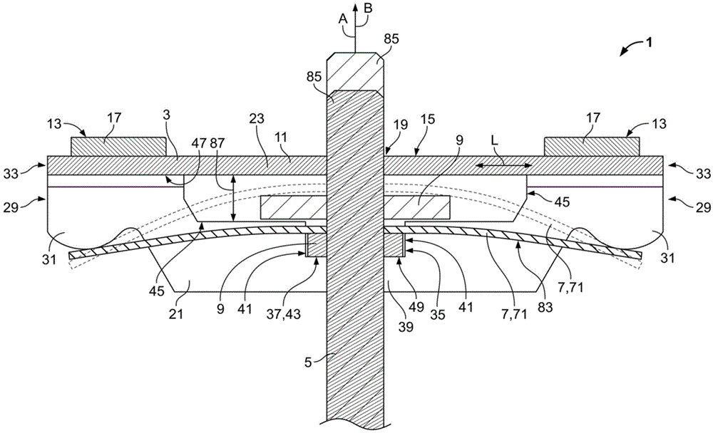
图1是根据本发明的平行于触桥的纵向方向且平行于致动方向的通过触桥布置的中截面图;Figure 1 is a mid-section view through the contact bridge arrangement parallel to the longitudinal direction of the contact bridge and parallel to the actuation direction according to the present invention;
图2是平行于致动方向且垂直于触桥的纵向方向的通过来自图1的触桥布置的中截面图;Figure 2 is a mid-section view through the contact bridge arrangement from Figure 1 parallel to the actuation direction and perpendicular to the longitudinal direction of the contact bridge;
图3是反向于致动方向的在来自图1的触桥布置上的平面图;Fig. 3 is a plan view on the contact bridge arrangement from Fig. 1 opposite to the actuation direction;
图4是根据本发明的触桥布置的示意透视图,以分解图附加地示出了弹簧元件和致动机构。Figure 4 is a schematic perspective view of a contact bridge arrangement according to the invention, additionally showing the spring element and the actuating mechanism in an exploded view.
具体实施方式Detailed ways
在下文中,参考图1-3来描述根据本发明的触桥布置,其中以各种视图绘示了有利的实施例。这里,在图3中的平面图中,在触桥布置的内部中的一些元件由虚线绘示,以使得他们易于被看到。In the following, a contact bridge arrangement according to the invention is described with reference to Figures 1-3, wherein advantageous embodiments are depicted in various views. Here, in the plan view in FIG. 3, some elements in the interior of the contact bridge arrangement are drawn with dotted lines to make them easy to see.
根据本发明,触桥布置1具有触桥3、致动构件5、至少一个弹簧元件7和至少一个止动件9。According to the invention, the
触桥3基本上沿纵向方向L延伸,并以可移动的方式沿致动方向B保持在致动构件5上。在这种情况下,其在致动方向B上由至少一个弹簧元件7按压抵靠止动件9。The contact bridge 3 extends substantially in the longitudinal direction L and is held on the actuating
触桥3可以具有触桥本体11,触桥本体11沿纵向方向L延伸。至少两个接触表面13(其在致动方向B上是自由的)优选布置在触桥3上。接触表面13优选平行于纵向方向L且垂直于致动方向B延伸。接触表面13可以布置在触桥3或触桥本体11的上侧15的上面。接触表面13可以形成作为触桥上的接触区域或作为连接至触桥3的接触元件17。在纵向方向L上观察,接触表面13在致动构件5上位于彼此的对面。The contact bridge 3 may have a
触桥3优选具有用于致动构件5的引导孔19,引导孔19在致动方向B上通过触桥本体11和上侧15延伸。在纵向方向L上观察,引导孔19优选布置在触桥3的中间,并同样地优选在宽度方向Q上,宽度方向Q横向于纵向方向L和致动方向B分布。The contact bridge 3 preferably has a
触桥3具有两个腿部21,两个腿部21从触桥本体11反向于致动方向B延伸。两个腿部21在宽度方向Q上彼此相对,以使得致动构件5布置在它们之间。腿部21优选与触桥3一体地形成。例如,它们可以通过反向于致动方向B重塑触桥材料23来形成。腿部21形成触桥3的侧向表面25,侧向表面25至少部分地平行于纵向方向L且平行于致动方向B延伸。在这种情况下,腿部21优选不在致动方向上突出在触桥3的上侧15的上面。The contact bridge 3 has two
腿部21可以在纵向方向上在触桥3的整个长度27上延伸。这不是必须的,但是有利的,这是由于按照这种方式,可以通过重塑而快速地生产触桥3。因此不必要移除在纵向方向L上彼此相对的端部29处的材料。此外,该设计可以确保:相较于在致动方向上弯曲,触桥具有增加的稳定性。腿部21优选在纵向方向L上延伸至一定程度,以使得从纵向方向L上观察,腿部21至少部分地与接触表面13在相同的高度。按照这种方式,由至少一个弹簧元件7产生的弹簧力的良好的力传递通过触桥3实现在接触表面13上。The
在触桥3的端部33(端部33在纵向方向L上位于彼此的对面)的区域中,触桥3优选具有间隔件31,该间隔件31反向于致动方向B远离触桥本体11延伸。间隔件31优选与腿部21一体地形成。同样地,间隔件31优选在纵向方向L上与腿部21的端部29重合,或者形成腿部21的端部29。间隔件31可以用于使至少一个弹簧元件7倚靠触桥3,以使得弹簧元件7可以在致动方向B上在触桥3上产生弹簧力。弹簧元件7可以通过间隔件被施加预应力。触桥3优选地分别在两个腿部21的两个端部29处具有间隔件31,这意味着一共设置有四个间隔件31。In the region of the
两个腿部21中的每一个优选具有孔35。孔35优选在宽度方向Q上延伸通过腿部21。在纵向方向L上观察,孔35可以特别地被布置在腿部的中间。孔35可以用来接收止动件9。下文将参考止动件9进一步详细描述止动件9和孔35之间的相互作用。在下文中,将更详细地探讨孔35的配置。孔35可以平行于致动方向通过腿部21延伸,直至平行于致动方向B分布的壁区段37。壁区段37可以是孔35的端部,该端部定位为反向于致动方向B。壁区段37可以是腿部21的腹板(web)39的部分,该腹板39限制了孔35反向于致动方向B。腹板39基本上平行于纵向方向L分布。Each of the two
孔35可以在致动方向B上从壁区段37延伸,该孔由两个侧向壁区段41侧向包围(flank),从纵向方向L上观察,该两个侧向壁区段41位于彼此的对面。壁区段37可以,特别是与侧向壁区段41联合在一起,代表用于止动件9的座43。侧向壁区段41可以代表用于止动件9的沿致动方向B的引导件。The
实施例示出的每个腿部21具有两个安装槽45。安装槽45基本上横向于致动方向B或在纵向方向L上分布,并远离座43延伸。在这种情况下,实施例示出的两个安装槽45在纵向方向L上在相反的方向上的远离座43延伸。安装槽45可以在致动方向B上延伸,直至触桥本体11的下侧47。安装槽45并非必须平行于纵向方向L分布。它们也可以倾斜地朝向座43分布。The embodiment shown has two mounting
安装槽45可以与孔35一起在腿部21中形成公共凹陷49。公共凹陷49可以具有T形,该T形的垂直腿部平行于致动方向B分布并由孔35形成,而该T形的两个水平腿部由安装槽45形成。原则上,还可能的是,每个腿部21仅具有一个安装槽45,该安装槽朝向腿部端部29远离孔35延伸。在这种情况下,两个腿部21可以形成为使得两个安装槽45分别在纵向方向L的两个相反的方向上分布。The mounting
根据本发明,触桥3优选地制造为冲压弯曲零件。为此,触桥材料23,其开始是平坦的,可以被冲压,由此触桥3的形状由腿部21、凹陷49以及引导孔19形成。为了不取走太多的触桥3的材料,例如当生产安装槽45时触桥本体11的材料,例如在引导孔19周围的区域中的凹陷49,可以围绕引导孔19形成环形区段51,该环形区段51具有充足的触桥材料23以保证引导孔的区域中的触桥3的稳定性。According to the invention, the contact bridge 3 is preferably produced as a stamped and bent part. For this purpose, the
在下文中,参考图1和图3以及绘示在图4的下面的区域中的致动构件5来描述本发明的致动构件5。致动构件5具有弹簧基座53,弹簧基座53可以用来支撑至少一个弹簧元件7。弹簧基座53优选形成为致动构件5的凸缘形状的区段55的部分。凸缘形状的区段55可以特别地由致动构件5上的凸缘形成。凸缘形状的区段55可以特别地与剩余的致动构件5一体地形成,或者可以连接至其。剩余的致动构件5优选为杆形或轴形。然而,进一步的技术有利的配置也是可能的。致动构件5可以用来致动触桥布置1通过致动器系统。In the following, the actuating
凸缘形状的区段55不仅具有弹簧基座53,例如通过其上侧57形成,而且还形成止动件9。止动件9具有止动表面59,止动表面59由凸缘形状的区段的下侧61形成。上侧57和下侧61与致动方向B相关,即上侧57指向致动方向B且下侧61指向反向于该方向。止动件9具有两个止动表面59,这两个止动表面59横向于致动方向B位于彼此的对面。凸缘形状的区段55因此是形成弹簧基座53和止动件9两者的部件。止动件9和弹簧基座53由凸缘形状的区段55一体地配置。图3在两个不同的位置以虚线示出了止动件9。The flange-shaped
凸缘形状的区段55或止动件9具有总体伸长的形状。在这种情况下,从横向于致动方向B观察,其具有长度63和宽度65。在插入触桥3的状态中,如图1-3以及图4的上区域所绘示,止动件的长度63优选至少和触桥3的外部宽度67一样大,至少在腿部21的区域中。在这种情况下,平行于宽度方向Q来测量外部宽度67。止动件的宽度65优选小于腿部21的内部间隔69。平行于触桥3的外部宽度67来测量腿部21的内部间隔69。The flange-shaped
触桥布置1具有弹簧元件7,弹簧元件7优选由叶片弹簧71形成。可替代地,弹簧元件7也可以由螺旋弹簧或其他合适的弹簧元件形成。组合的布置也是可能的,其中有若干叶片弹簧或者至少一个叶片弹簧和至少一个螺旋弹簧的组合。然而,为了简洁起见,在下文的描述中使用单独的叶片弹簧71。The
叶片弹簧71具有总体伸长的形状,且在布置在触桥3的状态中,平行于触桥的纵向方向L分布。叶片弹簧71在中间区域具有用于致动构件5的插入孔73。致动构件5可以螺纹穿过叶片弹簧71的插入孔73,从而叶片弹簧71横向于致动方向B主动地保持在致动构件上。在插入状态,叶片弹簧71倚靠弹簧基座53。致动构件5因此可以在致动方向B上(或反之亦然)经由弹簧基座53在叶片弹簧71上施加压力。The leaf springs 71 have an overall elongated shape, and in the state of being arranged in the contact bridges 3 are distributed parallel to the longitudinal direction L of the contact bridges. The leaf spring 71 has an
在非插入状态,如图4的下区域所示,叶片弹簧71优选在横向于致动方向B分布的平面中分布。因此,叶片弹簧71可以特别容易地由弹簧钢切割出或冲压出。In the non-inserted state, as shown in the lower area of FIG. 4 , the leaf springs 71 are preferably distributed in a plane transverse to the actuation direction B distribution. The leaf spring 71 can thus be cut or stamped out of spring steel particularly easily.
在其端部75(端部75在纵向方向L上位于彼此的对面)处,叶片弹簧优选具有端部宽度77,端部宽度77至少和触桥3的外部宽度67一样大。因此,触桥3的间隔件31可以倚靠叶片弹簧71的端部75。可以通过在其端部75具有截面加宽部79的叶片弹簧71来实现宽度77,在截面加宽部79中叶片弹簧71相对于位于端部75之间的其他叶片弹簧71被加宽。在纵向方向上观察,叶片弹簧71在端部75之间具有小于端部宽度77的中间区域宽度81。中间区域宽度81优选小于腿部21的内部间隔69。因此,叶片弹簧71可以在致动方向B上在腿部21之间以可移动的方式被引导,至少由没有超出中间区域宽度81的区域引导。At their ends 75 , which are located opposite each other in the longitudinal direction L, the leaf spring preferably has an
在下文中,以组装状态描述本发明。在图1中,以实线和淡剖面线绘示的止动件9与以实线绘示的叶片弹簧71示出了组装状态。在图4中,叶片弹簧由虚线表示,这是由于其否则是被隐藏的。In the following, the present invention is described in an assembled state. In FIG. 1 , the
触桥3沿致动方向B以可移动的方式被保持在致动构件5上。在这种情况下,触桥3至少被突出通过引导孔19的致动构件5引导。沿致动方向B进一步的引导可能是由于止动件9被两个腿部21的侧向壁区段41引导在孔35中。The contact bridge 3 is held on the
配置为叶片弹簧71的弹簧元件7被支撑在弹簧基座53上并在致动方向B上按压触桥3。叶片弹簧71倚靠弹簧基座53,并通过其倚靠间隔件31的端部75按压抵靠触桥。止动件9和弹簧基座53两者都位于弹簧元件7的背离触桥3的侧面83上。The spring element 7 configured as a leaf spring 71 is supported on the
止动件9穿过两个孔35,并通过叶片弹簧71按压抵靠两个壁区段37。在非接触的状态,如图1-4所示,止动件9倚靠壁区段37。两个孔35形成用于止动件9的两个座43,从分别承载在其上的壁区段37和侧向壁区段41。在座43中,止动件9以形式适配的方式保持为反向于致动方向且横向于致动方向,或在纵向方向L上。止动件9仅在一个致动方向上可以移出每个座43,必须克服叶片弹簧71的弹簧力。当使用根据本发明的触桥布置1时,优选确保止动件9不在致动方向B上移动超出侧向壁区段41,以使得其进入安装槽35中的操作。止动件9优选仅在其由侧向壁区段41引导的区域中移动。The
触桥3以其腿部21包围弹簧元件7或叶片弹簧71。在这种情况下,触桥3至少部分地包围体积V,叶片弹簧71被接收在体积V中。按照这种方式,可能节省用于触桥布置1的构造空间。The contact bridge 3 surrounds the spring element 7 or leaf spring 71 with its
从纵向方向L观察,触桥3具有基本上U形的截面。该U形截面基本上由触桥本体11形成(作为U的基部和远离基部延伸的两个腿部21),通过该U形截面,触桥3可以具有抵抗致动方向B上的弯曲的高度稳定性。Viewed in the longitudinal direction L, the contact bridge 3 has a substantially U-shaped cross section. This U-shaped section is substantially formed by the contact bridge body 11 (as the base of the U and the two
以下是根据本发明的触桥布置可以如何组装的简要说明。在这种情况下,假设触桥3已具有其最终形式,且凸缘形状的区段55已呈现在致动构件5上。首先,叶片弹簧71通过其插入孔73就位在致动构件5上,直至其倚靠弹簧基座53。随后致动构件5,与叶片弹簧71一起,在致动方向B上被插入触桥3。在这种情况下,凸缘形状的区段55或止动件9取向为使得其纵向方向平行于触桥3的纵向方向L分布。按照这种方式,止动件9适配在两个腿部21之间。由于叶片弹簧71在其端部75具有大于触桥3的外部宽度67的端部宽度77,一旦达到间隔件31的高度(在致动方向B上观察),叶片弹簧71的端部75可能已静止在间隔件31上。当进一步插入时,叶片弹簧71可以拱起(arch),使叶片弹簧71的围绕插入孔73的区域定位为比端部75更接近触桥本体11,端部75被间隔件31推动远离叶片弹簧71的中间区域。因此,在插入过程中必须克服弹簧71的弹簧张力。The following is a brief description of how the contact bridge arrangement according to the present invention can be assembled. In this case it is assumed that the contact bridge 3 has already taken its final form and that the flange-shaped
在插入过程中,致动构件5的上端85被插入触桥3的引导孔19。致动构件5在致动方向B上移动,直至止动件9被布置在与安装槽45相同的高度。这在图1中由粗剖面线的致动构件5和止动件9以及虚线的叶片弹簧71来绘示。在这种情况下,叶片弹簧71可以拱起,直至其倚靠触桥本体11的下侧47。由于很大的拱起导致叶片弹簧71在致动方向B上从止动件9提升离开,止动件9通过导致叶片弹簧71的拱起与触桥本体11的下侧47分隔开。当规定安装槽45的尺寸时,这可以被纳入考虑。这意味着安装槽45可以具有安装槽高度87,这使得可能把止动件9带至安装槽45的高度,即使在止动件9通过导致叶片弹簧71的拱起与触桥本体11的下侧47分隔开的情况下。During insertion, the
如果止动件9或凸缘形状的区段55位于与安装槽45同样的高度,则致动构件5可以围绕轴线A旋转,轴线A平行于致动方向B分布且在中间通过致动构件5的纵向轴线且通过引导孔19。在这种情况下,止动件9可以移动通过两个腿部21的安装槽45,并被引导至孔35。一旦止动件9取向为横向于触桥3的纵向方向L时,其被布置在座43上。随后,可以通过叶片弹簧71的弹簧力将止动件9按压进入两个座43。如果止动件9被布置在两个座43中,其通过其两个止动表面59倚靠两个壁区段37。通过安装槽45、座43以及止动件9形成致动构件5和触桥3之间的卡口连接。If the
下文给出了未在附图中绘示的可替代地配置和安装方法的简要说明。在可替代地实施例中,触桥3可以形成为没有安装槽45。取而代之的是,每个腿部21仅具有一个孔35以及用于止动件9的一个座43。在安装前,触桥3不形成为使得U形截面形成,而是使得两个腿部21甚至比在U形截面的情况中彼此更加分隔开。随后致动构件5和弹簧元件7被带入期望的位置。随后触桥3的腿部21拱起,直至产生触桥3的最终形状。这可以特别地保持U形截面。当反向于致动方向B重塑触桥3或弯曲腿部21时,止动件9可以在触桥3的两侧上穿入孔35,从而其被布置在每个腿处的座43中。在该实施例中,在致动方向上观察,止动件9或凸缘形状的区段55可以形成为圆形,即圆形止动件。其也可以同样地具有正方形形状,或其他合适的形状。A brief description of alternative arrangements and installation methods not shown in the accompanying drawings is given below. In an alternative embodiment, the contact bridge 3 may be formed without the mounting
附图标记reference number
1 触桥布置1 contact bridge arrangement
3 触桥3 touch bridge
5 致动构件5 Actuating member
7 弹簧元件7 Spring element
9 止动件9 Stopper
11 触桥本体11 Contact bridge body
13 接触表面13 Contact surfaces
15 上侧15 upper side
17 接触元件17 Contact elements
19 引导孔19 Pilot hole
21 腿部21 Legs
23 触桥材料23 Contact bridge material
25 侧向表面25 Lateral surfaces
27 触桥的长度27 Length of touch bridge
29 腿部在纵向方向上的端部29 The end of the leg in the longitudinal direction
31 间隔件31 Spacers
33 触桥在纵向方向上的端部33 The end of the contact bridge in the longitudinal direction
35 孔35 holes
37 壁区段37 Wall Sections
39 腹板39 Web
41 侧向壁区段41 Lateral wall section
43 座43 seats
45 安装槽45 Mounting slot
47 触桥本体的下侧47 Underside of the bridge body
49 凹陷49 Sag
51 环形区段51 Ring segment
53 弹簧基座53 Spring base
55 凸缘形状的区段55 Flange shaped segment
57 凸缘形状的区段的上侧57 Upper side of flange-shaped section
59 止动表面59 Stop surface
61 凸缘形状的区段的下侧61 Underside of flange-shaped segment
63 止动件的长度63 Length of stop
65 止动件的宽度65 Width of stop
67 触桥的外部宽度67 External width of the bridge
69 腿部的内部间隔69 Internal spacing of the legs
71 叶片弹簧71 Leaf spring
73 插入孔73 Insertion hole
75 叶片弹簧的端部75 End of leaf spring
77 叶片弹簧的端部宽度77 End width of leaf spring
79 截面加宽部79 Section widening
81 中间区域宽度81 Middle area width
83 弹簧元件的背离触桥的侧面83 Side of the spring element facing away from the contact bridge
85 致动构件的上端部85 Upper end of actuating member
87 安装槽高度87 Mounting slot height
B 致动方向B Actuation direction
L 纵向方向L portrait orientation
Q 宽度方向Q width direction
V 体积。V volume.
Claims (15)
Applications Claiming Priority (2)
| Application Number | Priority Date | Filing Date | Title |
|---|---|---|---|
| DE102015212817.2A DE102015212817A1 (en) | 2015-07-08 | 2015-07-08 | Contact bridge arrangement for an electrical switching element |
| DE102015212817.2 | 2015-07-08 |
Publications (2)
| Publication Number | Publication Date |
|---|---|
| CN106340407A CN106340407A (en) | 2017-01-18 |
| CN106340407B true CN106340407B (en) | 2020-02-14 |
Family
ID=56404005
Family Applications (1)
| Application Number | Title | Priority Date | Filing Date |
|---|---|---|---|
| CN201610532246.2A Expired - Fee Related CN106340407B (en) | 2015-07-08 | 2016-07-07 | Contact bridge arrangement for an electrical switching element |
Country Status (5)
| Country | Link |
|---|---|
| US (1) | US10020129B2 (en) |
| EP (1) | EP3116015B1 (en) |
| JP (1) | JP6905801B2 (en) |
| CN (1) | CN106340407B (en) |
| DE (1) | DE102015212817A1 (en) |
Families Citing this family (7)
| Publication number | Priority date | Publication date | Assignee | Title |
|---|---|---|---|---|
| DE102015212818A1 (en) * | 2015-07-08 | 2017-01-12 | Te Connectivity Germany Gmbh | Contact bridge arrangement for an electrical switching element |
| DE102020203830A1 (en) * | 2020-03-25 | 2021-09-30 | Te Connectivity Germany Gmbh | Actuation device, in particular for a relay |
| DE112021007255A5 (en) | 2021-03-11 | 2023-12-28 | Pierburg Gmbh | CONTACT BRIDGE DEVICE FOR A SWITCH OF A HIGH VOLTAGE CONTACTOR OR HIGH VOLTAGE RELAY |
| DE112021007249A5 (en) | 2021-03-11 | 2023-12-28 | Pierburg Gmbh | CONTACT BRIDGE DEVICE FOR A SWITCH OF A HIGH VOLTAGE CONTACTOR OR HIGH VOLTAGE RELAY |
| WO2025031600A1 (en) | 2023-08-10 | 2025-02-13 | Pierburg Gmbh | Contact bridge arrangement for a high-voltage contactor or high-voltage relay, and high-voltage contactor or high-voltage relay having a contact bridge arrangement |
| WO2025124694A1 (en) * | 2023-12-12 | 2025-06-19 | Pierburg Gmbh | Contact bridge arrangement for a high-voltage contactor or high-voltage relay, and high-voltage contactor or high-voltage relay comprising a contact bridge arrangement |
| FR3162908A1 (en) * | 2024-05-31 | 2025-12-05 | Safran Electrical & Power | Electrical contactor including an arc-extinguishing device by extension |
Citations (2)
| Publication number | Priority date | Publication date | Assignee | Title |
|---|---|---|---|---|
| US3848206A (en) * | 1973-07-18 | 1974-11-12 | Essex International Inc | Electromagnetic solenoid with improved contact antibounce means |
| CN104704598A (en) * | 2012-12-05 | 2015-06-10 | 富士电机机器制御株式会社 | Electromagnetic contactor |
Family Cites Families (9)
| Publication number | Priority date | Publication date | Assignee | Title |
|---|---|---|---|---|
| DE2813699C2 (en) | 1978-03-30 | 1986-08-28 | Robert Bosch Gmbh, 7000 Stuttgart | Electromagnetic switch, in particular for starting devices for internal combustion engines |
| EP0304539B1 (en) * | 1984-03-31 | 1993-02-03 | Square D Company (Deutschland) Gmbh | Switching bridge for electrical switching devices, particularly for contactors |
| FR2717003B1 (en) * | 1994-03-04 | 1996-04-12 | Radiall Sa | Switching device for opening and closing an electric line. |
| JPH10116540A (en) * | 1996-10-11 | 1998-05-06 | Nec Shizuoka Ltd | Seesaw type pushbutton switch for small sized electronic equipment |
| FR2813988B1 (en) * | 2000-09-08 | 2003-10-17 | Schneider Electric Ind Sa | SWITCHING DEVICE FOR A SWITCHING APPARATUS |
| JP2002278695A (en) * | 2001-03-15 | 2002-09-27 | Hosiden Corp | Multi-directional input device |
| JP5359960B2 (en) * | 2010-03-30 | 2013-12-04 | 三菱電機株式会社 | Contact switch |
| JP5884034B2 (en) * | 2011-03-22 | 2016-03-15 | パナソニックIpマネジメント株式会社 | Contact device |
| DE102012201967B4 (en) | 2012-02-09 | 2019-01-17 | Te Connectivity Germany Gmbh | Switching contact assembly and kit and assembly method for this |
-
2015
- 2015-07-08 DE DE102015212817.2A patent/DE102015212817A1/en not_active Ceased
-
2016
- 2016-07-01 US US15/200,095 patent/US10020129B2/en active Active
- 2016-07-04 JP JP2016132207A patent/JP6905801B2/en not_active Expired - Fee Related
- 2016-07-07 CN CN201610532246.2A patent/CN106340407B/en not_active Expired - Fee Related
- 2016-07-08 EP EP16178664.5A patent/EP3116015B1/en active Active
Patent Citations (2)
| Publication number | Priority date | Publication date | Assignee | Title |
|---|---|---|---|---|
| US3848206A (en) * | 1973-07-18 | 1974-11-12 | Essex International Inc | Electromagnetic solenoid with improved contact antibounce means |
| CN104704598A (en) * | 2012-12-05 | 2015-06-10 | 富士电机机器制御株式会社 | Electromagnetic contactor |
Also Published As
| Publication number | Publication date |
|---|---|
| CN106340407A (en) | 2017-01-18 |
| EP3116015B1 (en) | 2022-12-28 |
| DE102015212817A1 (en) | 2017-01-12 |
| JP6905801B2 (en) | 2021-07-21 |
| JP2017022101A (en) | 2017-01-26 |
| US20170011863A1 (en) | 2017-01-12 |
| EP3116015A1 (en) | 2017-01-11 |
| US10020129B2 (en) | 2018-07-10 |
Similar Documents
| Publication | Publication Date | Title |
|---|---|---|
| CN106340407B (en) | Contact bridge arrangement for an electrical switching element | |
| US9978537B2 (en) | Contact bridge arrangement for an electrical switching element | |
| JP6235033B2 (en) | Spring force terminal connecting portion and electric device having the same | |
| JP6206978B2 (en) | Switch contact subassembly having switch contact bridge and contact bridge retaining member | |
| JP6205370B2 (en) | Linear bearing and solenoid equipped therewith | |
| JP2018533185A (en) | Coupling terminal | |
| JP2015510236A5 (en) | ||
| CN113169464A (en) | Spring connecting terminal | |
| JP5984221B2 (en) | Opening and closing device including a movable part having improved dynamics | |
| CN103503102A (en) | Electrical snap action switch | |
| CN107731627B (en) | Contact pushing assembly and electromagnetic relay | |
| KR101992436B1 (en) | Magnetic system of electromagnetic repeater | |
| CN110504139B (en) | Yoke assembly, magnetic assembly and magnetic switch device of a magnetic switch device such as a relay | |
| CN103000391B (en) | A moving contact assembly | |
| JP2011204550A (en) | Operating device | |
| JP2017085690A (en) | Electric wire guide | |
| JP2015076325A (en) | Contactor | |
| CN102473535A (en) | Contact arrangement for an electromagnetic switching device | |
| JP6442604B2 (en) | Contact spring and cradle relay | |
| EP3582242A1 (en) | Electrical switch device | |
| JP2021027037A (en) | Double-armature relay | |
| CN113826177A (en) | Switchgear with self-cleaning contacts | |
| CN204332842U (en) | Contact mechanism of AC contactor | |
| JP2015026591A (en) | Movable contact for switch | |
| WO2020137508A1 (en) | Terminal block |
Legal Events
| Date | Code | Title | Description |
|---|---|---|---|
| C06 | Publication | ||
| PB01 | Publication | ||
| SE01 | Entry into force of request for substantive examination | ||
| SE01 | Entry into force of request for substantive examination | ||
| GR01 | Patent grant | ||
| GR01 | Patent grant | ||
| CF01 | Termination of patent right due to non-payment of annual fee |
Granted publication date: 20200214 |
|
| CF01 | Termination of patent right due to non-payment of annual fee |