CN106295485B - Fingerprint identification module and mobile device - Google Patents
Fingerprint identification module and mobile device Download PDFInfo
- Publication number
- CN106295485B CN106295485B CN201510325371.1A CN201510325371A CN106295485B CN 106295485 B CN106295485 B CN 106295485B CN 201510325371 A CN201510325371 A CN 201510325371A CN 106295485 B CN106295485 B CN 106295485B
- Authority
- CN
- China
- Prior art keywords
- module
- flange
- fingerprint identification
- identification module
- mobile device
- Prior art date
- Legal status (The legal status is an assumption and is not a legal conclusion. Google has not performed a legal analysis and makes no representation as to the accuracy of the status listed.)
- Active
Links
Images


Classifications
-
- G—PHYSICS
- G06—COMPUTING OR CALCULATING; COUNTING
- G06V—IMAGE OR VIDEO RECOGNITION OR UNDERSTANDING
- G06V40/00—Recognition of biometric, human-related or animal-related patterns in image or video data
- G06V40/10—Human or animal bodies, e.g. vehicle occupants or pedestrians; Body parts, e.g. hands
- G06V40/12—Fingerprints or palmprints
- G06V40/13—Sensors therefor
- G06V40/1318—Sensors therefor using electro-optical elements or layers, e.g. electroluminescent sensing
-
- G—PHYSICS
- G06—COMPUTING OR CALCULATING; COUNTING
- G06V—IMAGE OR VIDEO RECOGNITION OR UNDERSTANDING
- G06V40/00—Recognition of biometric, human-related or animal-related patterns in image or video data
- G06V40/10—Human or animal bodies, e.g. vehicle occupants or pedestrians; Body parts, e.g. hands
- G06V40/12—Fingerprints or palmprints
- G06V40/13—Sensors therefor
- G06V40/1306—Sensors therefor non-optical, e.g. ultrasonic or capacitive sensing
-
- G—PHYSICS
- G06—COMPUTING OR CALCULATING; COUNTING
- G06V—IMAGE OR VIDEO RECOGNITION OR UNDERSTANDING
- G06V40/00—Recognition of biometric, human-related or animal-related patterns in image or video data
- G06V40/10—Human or animal bodies, e.g. vehicle occupants or pedestrians; Body parts, e.g. hands
- G06V40/12—Fingerprints or palmprints
- G06V40/13—Sensors therefor
- G06V40/1329—Protecting the fingerprint sensor against damage caused by the finger
Landscapes
- Engineering & Computer Science (AREA)
- Human Computer Interaction (AREA)
- Physics & Mathematics (AREA)
- General Physics & Mathematics (AREA)
- Multimedia (AREA)
- Theoretical Computer Science (AREA)
- Telephone Set Structure (AREA)
- Image Input (AREA)
Abstract
The present disclosure relates to fingerprint identification module and mobile device, this fingerprint identification module can include: the module body is positioned at any side of a liquid crystal display module in the mobile equipment after the fingerprint identification module is installed on the mobile equipment, and the first side of the module body is close to and parallel to any side; a flange structure, the flange structure comprising: the flange body is matched with the module body in specification and surrounds all side edges of the module body; and the flange edge is formed by outwards protruding the flange body and is only positioned at the non-first side edge. Through this disclosed technical scheme, can shorten the interval between fingerprint identification module and the liquid crystal display module of mobile device to help reduce the size and specification of mobile device, realize the frivolousness of mobile device.
Description
Technical Field
The utility model relates to the technical field of terminals, especially, relate to fingerprint identification module and mobile device.
Background
With the continuous development of science and technology, various types of mobile devices such as smart phones and tablet computers are increasingly integrated into the daily life and work of users. Due to the portable demand of users for mobile devices while avoiding affecting the display effect of the mobile devices, manufacturers are reducing the size of the mobile devices in various ways while keeping the screen size unchanged.
Disclosure of Invention
The present disclosure provides a fingerprint identification module and a mobile device to solve the deficiencies in the related art.
According to a first aspect of the embodiments of the present disclosure, a fingerprint identification module is provided, including:
the module body is positioned at any side of a liquid crystal display module in the mobile equipment after the fingerprint identification module is installed on the mobile equipment, and the first side of the module body is close to and parallel to any side; the specification of the module body is matched with a reserved through hole in cover plate glass of the mobile equipment and extends out of the bottom of the reserved through hole to form a preset key;
a flange structure, the flange structure comprising:
the flange body is matched with the module body in specification and surrounds all side edges of the module body;
the flange edge is formed by outwards protruding the flange body and is only positioned at the non-first side edge; the fingerprint identification module is arranged on the mobile equipment, the flange edge is positioned at the bottom of the cover plate glass, and the periphery of the reserved through hole is matched with the cover plate glass, so that the module body is prevented from falling off from the mobile equipment.
Optionally, any one of the side edges is a bottom side edge.
Optionally, the cross-section of the module body is rectangular, and the flange edge is located at a second side edge parallel to the first side edge, and a third side edge and a fourth side edge perpendicular to the first side edge.
Optionally, the cross section of the module body is rectangular, and the flange sides are located at a third side and a fourth side perpendicular to the first side.
Optionally, the outer wall of the flange body corresponding to the first side is closely attached to the any one side.
Optionally, after the fingerprint identification module is installed on the mobile device, the flange body extends out from the bottom of the reserved through hole, and the top end face of the flange body is not lower than the top end face of the module body.
According to a second aspect of embodiments of the present disclosure, there is provided a mobile device comprising: the fingerprint identification module as described in any of the above embodiments.
The technical scheme provided by the embodiment of the disclosure can have the following beneficial effects:
according to the above embodiment, this disclosure is close to under the condition of the liquid crystal display module at the first side of the module body of fingerprint identification module, only carries out the part to this module body and surrounds at non-first side department through making the flange structure to avoid the flange structure to cause the separation between fingerprint identification module and liquid crystal display module, can shorten the interval between the two as far as possible, help reducing mobile device's size specification, realize mobile device's frivolousness.
It is to be understood that both the foregoing general description and the following detailed description are exemplary and explanatory only and are not restrictive of the disclosure.
Drawings
The accompanying drawings, which are incorporated in and constitute a part of this specification, illustrate embodiments consistent with the present disclosure and together with the description, serve to explain the principles of the disclosure.
Fig. 1 is a schematic structural diagram of a mobile device in the related art.
Fig. 2 is a schematic perspective view of a fingerprint identification module in the related art.
Fig. 3 is a schematic cross-sectional view of a mobile device in the related art.
Fig. 4 is a schematic structural diagram illustrating a fingerprint recognition module according to an exemplary embodiment.
Fig. 5 is a schematic cross-sectional diagram illustrating a mobile device in accordance with an example embodiment.
Fig. 6 is a schematic structural diagram of another fingerprint identification module according to an exemplary embodiment.
FIG. 7 is a schematic cross-sectional diagram illustrating a mobile device in accordance with an example embodiment.
Detailed Description
Reference will now be made in detail to the exemplary embodiments, examples of which are illustrated in the accompanying drawings. When the following description refers to the accompanying drawings, like numbers in different drawings represent the same or similar elements unless otherwise indicated. The implementations described in the exemplary embodiments below are not intended to represent all implementations consistent with the present disclosure. Rather, they are merely examples of apparatus and methods consistent with certain aspects of the present disclosure, as detailed in the appended claims.
Fig. 1 is a schematic structural diagram of a mobile device in the related art, and as shown in fig. 1, in the related art, more and more mobile devices 1 are configured with fingerprint identification modules 2, so that user identity authentication is implemented through a fingerprint identification function, thereby improving security and reducing complexity of user operation.
As shown in fig. 2, the fingerprint recognition module 2 in the related art includes two parts: a module body 21 and a flange structure 22, and the flange structure 22 is further composed of a flange body 221 and a flange edge 222. Wherein, the center of the flange structure 22 forms a hollow area matched with the specification of the module body 21, so that the module body 21 can be placed in the area and is mutually connected with the inner wall of the flange structure 22; and the flange edge 222 is formed by the flange structure 22 protruding to the periphery; of course, it can be considered that the flange body 221 and the flange edge 222 form a stepped structure.
Because the upper surface of mobile device 1 is cover plate glass (not mark in the figure), for the convenience of customers and fingerprint identification module 2 carry out direct contact, need set up on cover plate glass and reserve the through-hole to make fingerprint identification module 2's module body 21 stretch out the back by this reservation through-hole bottom, form and predetermine the button. Wherein, a functional unit for fingerprint collection all is located module body 21, and flange structure 22 is used for protecting and decorating module body 21 to and through the cooperation of flange 222 between reservation through-hole department and cover plate glass, thereby avoid module body 21 to drop from reserving the through-hole.
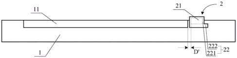
For example, as shown in fig. 3, an inner diameter of a through hole formed in the cover glass of the mobile device 1 is smaller than an outer diameter of the flange structure 22 (i.e., a distance between outer walls of two parallel flange edges 222), and the flange edges 222 penetrate through the through hole, so as to ensure that the module body 21 cannot fall off.
However, since the flange edge 222 is located around the flange body 221, when the fingerprint identification module 2 is installed in the mobile device 1, the distance D between the module body 21 and the liquid crystal display module 11 is not less than the width of one flange edge 222, which affects the trend of the mobile device 1.
Therefore, the present disclosure solves the above technical problems in the related art through structural improvement of the fingerprint identification module 2.
Fig. 4 is a schematic structural diagram of a fingerprint identification module according to an exemplary embodiment, and as shown in fig. 4, the fingerprint identification module 2 may include:
the module body 21 is located at any one side of the liquid crystal display module 11 (see fig. 3) in the mobile device 1 after the fingerprint identification module 2 is installed in the mobile device 1 (see fig. 3), and a first side (for convenience of description, it is assumed that the first side is an upper side in fig. 4) of the module body 21 is close to and parallel to the any one side; the specification of the module body 21 is matched with a reserved through hole in cover glass of the mobile device 1, and the module body extends out of the bottom of the reserved through hole to form a preset key;
a flange structure 22, the flange structure 22 comprising:
the flange body 221 is matched with the module body 21 in specification, and surrounds all sides of the module body 21;
a flange edge 222 formed by the flange body 221 protruding outward, wherein the flange edge 222 is only located at a non-first side edge; after the fingerprint identification module 2 is installed on the mobile device 1, the flange 222 is located at the bottom of the cover glass and is matched with the cover glass around the reserved through hole, so as to prevent the module body 21 from falling off from the mobile device 1.
In this embodiment, since the first side of the module body 21 is close to and parallel to the liquid crystal display module 11, and the flange 222 is only disposed at the non-first side, it can be seen that: at first side department, there is not flange limit 222 between fingerprint identification module 2 and the liquid crystal display module 11, therefore on the basis that fig. 3 shows, the spacing distance D between fingerprint identification module 2 and the liquid crystal display module 11 can not receive the hindrance of flange limit 222, and realizes further shortening. For example, as shown in fig. 5, a new spacing distance D' between the module body 21 and the liquid crystal display module 11 is reduced by at least the width distance of one flange 22 compared with the spacing distance D; when the outer wall of the flange body 221 is closely attached to the any one side of the lcd module 11, the minimum new distance D' can be obtained.
Therefore, the fingerprint identification module 2 in the embodiment shown in fig. 5 provides a smaller space occupation requirement than that of the related art, which is helpful for performing more compact combination and adjustment on other structures inside the mobile device 1, so as to reduce the overall space occupation inside the mobile device 1, i.e. to achieve the lightness and thinness of the mobile device 1.
1. Set up the position
Although fig. 1 shows the case where the fingerprint recognition module 2 is located at the bottom of the mobile device 1, it is actually just as described in the above embodiment: fingerprint identification module 2 can be located any side department of liquid crystal display module 11 in mobile device 1, and just as an exemplary embodiment, this fingerprint identification module 2 is located between liquid crystal display module 11 and mobile device 1's bottom side, and this fingerprint identification module 2 can also be used for realizing the physical button of function such as "homepage" this moment.
2. Flange 222 construction
For convenience of illustration, when the cross section of the module body 21 is rectangular (possibly chamfered based on the processing technology and the requirement of aesthetic quality), the structure of the flange 222 will be described by taking the upper side of the module body 21 as the first side.
As an exemplary embodiment, as shown in fig. 4 and 5, the flange side 222 may be located at a second side (i.e., a lower side) parallel to the first side, and third and fourth sides (i.e., left and right sides) perpendicular to the first side.
As another exemplary embodiment, as shown in fig. 6 and 7, the flange side 222 may be located at third and fourth sides (i.e., left and right sides) perpendicular to the first side. In this embodiment, the flange edges 222 at the two parallel side edges are retained, so that the stability of the fingerprint identification module 2 can be ensured, and the module body 21 is prevented from falling off; simultaneously, because there is not flange 222 at first side and second side department for not only can shorten the distance between fingerprint identification module 2 and the liquid crystal display module 11, can also shorten the distance between fingerprint identification module 2 and the side of mobile device 1, thereby further reduced fingerprint identification module 2's space and occupy the demand, can help the mobile device to realize further frivolousization.
3. Height of flange
As an exemplary embodiment, after the fingerprint identification module 2 is installed on the mobile device 1, the flange body 221 extends out from the bottom of the reserved through hole, and the top end surface of the flange body 221 is not lower than the top end surface of the module body 21. In this embodiment, when the flange body 221 is disposed around the module body 21, the module body 21 can be decorated, and direct contact and friction between the module body 21 and the cover glass can be avoided; meanwhile, the flange body 221 protruding in height can also avoid direct contact and friction to the module body 21 from the outside under the condition that the mobile device 1 is turned over on a plane, and the like, thereby being beneficial to protecting the module body 21 and prolonging the service life of the module body.
Other embodiments of the disclosure will be apparent to those skilled in the art from consideration of the specification and practice of the disclosure disclosed herein. This application is intended to cover any variations, uses, or adaptations of the disclosure following, in general, the principles of the disclosure and including such departures from the present disclosure as come within known or customary practice within the art to which the disclosure pertains. It is intended that the specification and examples be considered as exemplary only, with a true scope and spirit of the disclosure being indicated by the following claims.
It will be understood that the present disclosure is not limited to the precise arrangements described above and shown in the drawings and that various modifications and changes may be made without departing from the scope thereof. The scope of the present disclosure is limited only by the appended claims.
Claims (7)
1. The utility model provides a fingerprint identification module which characterized in that includes:
the module comprises a module body, wherein the module body comprises a functional component for fingerprint acquisition, after the fingerprint identification module is installed on mobile equipment, the module body is positioned at any side edge of a liquid crystal display module in the mobile equipment, and a first side edge of the module body is close to and parallel to any side edge; the specification of the module body is matched with a reserved through hole in cover plate glass of the mobile equipment and extends out of the bottom of the reserved through hole to form a preset key;
a flange structure, the flange structure comprising:
the flange body is matched with the module body in specification and surrounds all side edges of the module body;
the flange edge is formed by outwards protruding the flange body and is only positioned at the non-first side edge; the fingerprint identification module is arranged on the mobile equipment, the flange edge is positioned at the bottom of the cover plate glass, and the periphery of the reserved through hole is matched with the cover plate glass, so that the module body is prevented from falling off from the mobile equipment.
2. The fingerprint identification module of claim 1, wherein the any side is a bottom side.
3. The fingerprint identification module of claim 1, wherein the module body is rectangular in cross-section, and the flange sides are located at a second side parallel to the first side, and at a third side and a fourth side perpendicular to the first side.
4. The fingerprint identification module of claim 1, wherein the module body is rectangular in cross-section, and the flange is located at a third side and a fourth side perpendicular to the first side.
5. The fingerprint identification module of claim 1, wherein an outer wall of the flange body corresponding to the first side is closely attached to the any one side.
6. The fingerprint identification module of claim 1, wherein after the fingerprint identification module is installed on the mobile device, the flange body extends from the bottom of the reserved through hole, and the top end surface of the flange body is not lower than the top end surface of the module body.
7. A mobile device, comprising: the fingerprint identification module of any one of claims 1-6.
Priority Applications (1)
| Application Number | Priority Date | Filing Date | Title |
|---|---|---|---|
| CN201510325371.1A CN106295485B (en) | 2015-06-12 | 2015-06-12 | Fingerprint identification module and mobile device |
Applications Claiming Priority (1)
| Application Number | Priority Date | Filing Date | Title |
|---|---|---|---|
| CN201510325371.1A CN106295485B (en) | 2015-06-12 | 2015-06-12 | Fingerprint identification module and mobile device |
Publications (2)
| Publication Number | Publication Date |
|---|---|
| CN106295485A CN106295485A (en) | 2017-01-04 |
| CN106295485B true CN106295485B (en) | 2021-07-23 |
Family
ID=57650008
Family Applications (1)
| Application Number | Title | Priority Date | Filing Date |
|---|---|---|---|
| CN201510325371.1A Active CN106295485B (en) | 2015-06-12 | 2015-06-12 | Fingerprint identification module and mobile device |
Country Status (1)
| Country | Link |
|---|---|
| CN (1) | CN106295485B (en) |
Families Citing this family (1)
| Publication number | Priority date | Publication date | Assignee | Title |
|---|---|---|---|---|
| CN108475088A (en) * | 2017-01-05 | 2018-08-31 | 华为技术有限公司 | Fingerprint module, its assemble method and the terminal including the fingerprint module |
Family Cites Families (10)
| Publication number | Priority date | Publication date | Assignee | Title |
|---|---|---|---|---|
| CN2776210Y (en) * | 2004-12-24 | 2006-05-03 | Vkr控股公司 | Installing location seat of window curtain |
| CN201610984U (en) * | 2009-10-30 | 2010-10-20 | 平高集团有限公司 | A square flange used in high voltage switch |
| US8736001B2 (en) * | 2010-06-18 | 2014-05-27 | Authentec, Inc. | Finger sensor including encapsulating layer over sensing area and related methods |
| JP4881465B2 (en) * | 2010-07-23 | 2012-02-22 | シャープ株式会社 | Push button switch structure and electronic device equipped with the same |
| US9030440B2 (en) * | 2012-05-18 | 2015-05-12 | Apple Inc. | Capacitive sensor packaging |
| US8786403B1 (en) * | 2012-10-05 | 2014-07-22 | Jeffery Robert Vangemert | Biometric identification scanner |
| KR101934714B1 (en) * | 2012-11-28 | 2019-01-03 | 삼성전자주식회사 | Key button apparatus |
| CN103793689B (en) * | 2014-01-27 | 2017-06-06 | 南昌欧菲光科技有限公司 | Encapsulation structure of fingerprint recognition sensor, electronic device and preparation method of fingerprint recognition sensor |
| CN104156710A (en) * | 2014-08-26 | 2014-11-19 | 南昌欧菲生物识别技术有限公司 | Fingerprint recognition device and terminal device |
| CN104391635B (en) * | 2014-11-26 | 2018-06-19 | 小米科技有限责任公司 | Solve the device and method of lock screen |
-
2015
- 2015-06-12 CN CN201510325371.1A patent/CN106295485B/en active Active
Also Published As
| Publication number | Publication date |
|---|---|
| CN106295485A (en) | 2017-01-04 |
Similar Documents
| Publication | Publication Date | Title |
|---|---|---|
| CN106027863B (en) | A camera base, camera and terminal | |
| CN203705745U (en) | Liquid crystal display device | |
| KR20160135349A (en) | Mobile terminal | |
| WO2017128677A1 (en) | Cover glass assembly | |
| CN203734707U (en) | Mobile phone SIM card holder structure | |
| CN106295485B (en) | Fingerprint identification module and mobile device | |
| CN204668559U (en) | Card holder and mobile terminal | |
| EP3525297A1 (en) | Electronic device | |
| US9229491B2 (en) | Tablet computer | |
| US10109919B2 (en) | Antenna structure | |
| CN105376365B (en) | A kind of mobile phone | |
| CN205304908U (en) | Mobile handset web frame | |
| CN206452438U (en) | Input module and electronic installation | |
| CN104168343A (en) | Mobile phone holder with buckle | |
| CN104463133A (en) | Whole plane type protection device for fingerprint identification and manufacturing method thereof | |
| CN202308536U (en) | A dual SIM card slot device | |
| CN103812976B (en) | Mobile phone card holder having fool-proof function | |
| CN104347285A (en) | Fixing structure of microswitch | |
| CN207782933U (en) | A kind of camera module and electronic equipment | |
| CN208973564U (en) | A kind of control circuit of food processor | |
| US20180092458A1 (en) | Desk | |
| CN205123819U (en) | Handset | |
| CN206479963U (en) | A kind of Terminal fingerprints Module-embedding structure | |
| CN208188786U (en) | Single-hand operated keyboard with palm rest structure | |
| CN204090423U (en) | Shield assemblies and containing its mobile terminal |
Legal Events
| Date | Code | Title | Description |
|---|---|---|---|
| C06 | Publication | ||
| PB01 | Publication | ||
| C10 | Entry into substantive examination | ||
| SE01 | Entry into force of request for substantive examination | ||
| GR01 | Patent grant | ||
| GR01 | Patent grant |