CN106295455B - Bar code indicating method and bar code reader - Google Patents
Bar code indicating method and bar code reader Download PDFInfo
- Publication number
- CN106295455B CN106295455B CN201610647272.XA CN201610647272A CN106295455B CN 106295455 B CN106295455 B CN 106295455B CN 201610647272 A CN201610647272 A CN 201610647272A CN 106295455 B CN106295455 B CN 106295455B
- Authority
- CN
- China
- Prior art keywords
- distance
- image
- bar code
- target
- barcode
- Prior art date
- Legal status (The legal status is an assumption and is not a legal conclusion. Google has not performed a legal analysis and makes no representation as to the accuracy of the status listed.)
- Expired - Fee Related
Links
Images


Classifications
-
- G—PHYSICS
- G06—COMPUTING OR CALCULATING; COUNTING
- G06K—GRAPHICAL DATA READING; PRESENTATION OF DATA; RECORD CARRIERS; HANDLING RECORD CARRIERS
- G06K7/00—Methods or arrangements for sensing record carriers, e.g. for reading patterns
- G06K7/10—Methods or arrangements for sensing record carriers, e.g. for reading patterns by electromagnetic radiation, e.g. optical sensing; by corpuscular radiation
- G06K7/14—Methods or arrangements for sensing record carriers, e.g. for reading patterns by electromagnetic radiation, e.g. optical sensing; by corpuscular radiation using light without selection of wavelength, e.g. sensing reflected white light
- G06K7/1404—Methods for optical code recognition
- G06K7/1439—Methods for optical code recognition including a method step for retrieval of the optical code
- G06K7/1443—Methods for optical code recognition including a method step for retrieval of the optical code locating of the code in an image
-
- G—PHYSICS
- G06—COMPUTING OR CALCULATING; COUNTING
- G06K—GRAPHICAL DATA READING; PRESENTATION OF DATA; RECORD CARRIERS; HANDLING RECORD CARRIERS
- G06K7/00—Methods or arrangements for sensing record carriers, e.g. for reading patterns
- G06K7/10—Methods or arrangements for sensing record carriers, e.g. for reading patterns by electromagnetic radiation, e.g. optical sensing; by corpuscular radiation
- G06K7/10544—Methods or arrangements for sensing record carriers, e.g. for reading patterns by electromagnetic radiation, e.g. optical sensing; by corpuscular radiation by scanning of the records by radiation in the optical part of the electromagnetic spectrum
- G06K7/10821—Methods or arrangements for sensing record carriers, e.g. for reading patterns by electromagnetic radiation, e.g. optical sensing; by corpuscular radiation by scanning of the records by radiation in the optical part of the electromagnetic spectrum further details of bar or optical code scanning devices
- G06K7/10861—Methods or arrangements for sensing record carriers, e.g. for reading patterns by electromagnetic radiation, e.g. optical sensing; by corpuscular radiation by scanning of the records by radiation in the optical part of the electromagnetic spectrum further details of bar or optical code scanning devices sensing of data fields affixed to objects or articles, e.g. coded labels
Landscapes
- Physics & Mathematics (AREA)
- Engineering & Computer Science (AREA)
- Electromagnetism (AREA)
- Health & Medical Sciences (AREA)
- General Health & Medical Sciences (AREA)
- Toxicology (AREA)
- Artificial Intelligence (AREA)
- Computer Vision & Pattern Recognition (AREA)
- General Physics & Mathematics (AREA)
- Theoretical Computer Science (AREA)
- Image Analysis (AREA)
- Character Input (AREA)
Abstract
The invention discloses a bar code indicating method and a bar code reader, comprising the following steps: capturing a target image of a target bar code by a bar code reader; analyzing the target image to obtain image parameters; judging whether the current distance between the bar code reader and the target bar code is a relative middle distance or not according to the image parameters; and when the current distance is judged to be the relative middle distance, the bar code reader sends out indicating light to the target bar code. Therefore, the number of times that the user repeatedly moves the bar code reader can be reduced, and the decoding efficiency is improved.
Description
Technical Field
The present invention relates to a barcode indicating method and a barcode reader, and more particularly, to a barcode indicating method and a barcode reader capable of effectively increasing a decoding success rate.
Background
A bar code (barcode) is a pattern recognition element in which a plurality of black bars and spaces having different widths are arranged according to a certain coding rule to express a group of information. The bar code can mark information such as the country of manufacture, manufacturer, name of goods, date of manufacture, book classification number, starting and ending place of mail, category, date, etc., so that the bar code is widely applied to many fields such as commodity circulation, book management, postal management, bank system, etc.
Referring to fig. 1, fig. 1 is a schematic diagram of a barcode reader 1 in the prior art for reading a barcode. As shown in fig. 1, the barcode reader 1 includes an image capturing unit 10 and a light emitting unit 12. When the barcode reader 1 reads a barcode, the light emitting unit 12 emits an indicating light 120 on the barcode for a user to identify the barcode to be read, and the image capturing unit 10 captures an image of the barcode. Since the positions of the image capturing unit 10 and the light emitting unit 12 are not overlapped, the traveling path of the indication light 120 and the image capturing path 100 of the image capturing unit 10 are not on the same line, and an angle is formed between the traveling path of the indication light 120 and the image capturing path 100 of the image capturing unit 10 as shown in fig. 1. If the distance from the barcode reader 1 is defined as a relatively short distance, a relatively medium distance and a relatively long distance from the near side as shown in fig. 1, the barcode indicated by the indication light 120 is consistent with the barcode captured by the image capturing unit 10 only when the barcode is within the relatively medium distance.
As shown in FIG. 1, both barcodes 20, 22 are located at relatively large distances and in close proximity to each other. If the user wants to read the barcode 20 with the barcode reader 1, the user directs the indication light 120 emitted by the light emitting unit 12 to the barcode 20. However, since the barcodes 20 and 22 are located at relatively far distances and close to each other, the image capturing unit 10 images the barcode 22 rather than the barcode 20. In this way, the barcode reader 1 decodes the barcode 22, not the barcode 20. Therefore, the user may mistake the decoding result of the barcode 22 as the decoding result of the barcode 20. If the user does not find the error in real time, the user may lose the error.
In addition, if the barcode 20 is located at a relatively long distance and no other barcode exists in the vicinity of the barcode, when the user directs the indication light 120 emitted by the light emitting unit 12 to the barcode 20, the image capturing unit 10 cannot capture the barcode image, which results in a decoding failure. At this time, the user needs to repeatedly move the barcode reader 1 so that the barcode 20 is located within a relatively middle distance range, and then the barcode 20 can be successfully decoded. The above operation is not only inefficient but also affects the user's use.
Disclosure of Invention
The present invention provides a barcode indicating method and a barcode reader capable of effectively increasing the decoding success rate, so as to solve the above problems.
To achieve the above object, the present invention provides a barcode indicating method, comprising the following steps:
capturing a target image of a target bar code by a bar code reader;
analyzing the target image to obtain image parameters;
judging whether the current distance between the bar code reader and the target bar code is an effective decoding distance or not according to the image parameters; and
when the current distance is judged to be the effective decoding distance, the bar code reader sends out indicating light to the target bar code.
Preferably, the method further comprises the following steps:
when the current distance is judged not to be the effective decoding distance, an alarm message is sent out from the bar code reader.
Preferably, the image parameter is image resolution, and the barcode indicating method further comprises the following steps:
when the image definition falls into a preset definition range, judging that the current distance is the effective decoding distance; and
and when the image definition falls outside the preset definition range, judging that the current distance is not the effective decoding distance.
Preferably, the method further comprises the following steps:
setting a target scanning line on a first interval of the target image;
analyzing the relative relation between at least two characteristic points on the gray scale distribution of the target scanning line according to the coding rule to obtain the image parameter, wherein the image parameter comprises at least one reference characteristic parameter;
when the at least one reference characteristic parameter is consistent with the corresponding at least one first preset characteristic parameter, judging that the current distance is a relatively long distance;
when the at least one reference characteristic parameter is consistent with at least one corresponding second preset characteristic parameter, judging that the current distance is the effective decoding distance; and
and when the at least one reference characteristic parameter is consistent with the corresponding at least one third preset characteristic parameter, judging that the current distance is a relatively short distance.
Preferably, the method further comprises the following steps:
capturing a plurality of sample images of a sample bar code at a plurality of preset distances by using the bar code reader, wherein the preset distances belong to the relatively long distance, part of the preset distances belong to the relatively medium distance, and the rest part of the preset distances belong to the relatively short distance;
setting a sample scanning line on a second interval of each sample image, wherein the decoding of the first interval and the second interval is the same; and
and analyzing the relative relationship between at least two characteristic points on the gray scale distribution of each sample scanning line according to the coding rule to obtain the at least one first preset characteristic parameter corresponding to the relatively long distance, the at least one second preset characteristic parameter corresponding to the relatively medium distance and the at least one third preset characteristic parameter corresponding to the relatively short distance.
Preferably, the relative relationship between the at least two feature points is pixel distance, gray scale difference value or combination thereof.
Preferably, the at least two feature points are two adjacent peak points and valley points, two adjacent peak points, two adjacent valley points or a combination thereof.
To achieve the above object, the present invention further provides a barcode reader, comprising:
the image capturing unit captures a target image of the target bar code;
a light emitting unit; and
the processing unit is electrically connected with the image acquisition unit and the light-emitting unit, analyzes the target image to obtain image parameters, judges whether the current distance between the bar code reader and the target bar code is an effective decoding distance according to the image parameters, and controls the light-emitting unit to emit indicating light on the target bar code when the processing unit judges that the current distance is the effective decoding distance.
Preferably, the mobile terminal further comprises an alarm unit electrically connected to the processing unit, and when the processing unit determines that the current distance is not the valid decoding distance, the processing unit controls the alarm unit to send an alarm message.
Preferably, the image parameter is an image sharpness, when the image sharpness falls within a predetermined sharpness range, the processing unit determines that the current distance is the effective decoding distance, and when the image sharpness falls outside the predetermined sharpness range, the processing unit determines that the current distance is not the effective decoding distance.
Preferably, the processing unit sets a target scan line in a first interval of the target image, the processing unit analyzes a relative relationship between at least two feature points on a gray scale distribution of the target scan line according to a coding rule to obtain the image parameter, the image parameter includes at least one reference feature parameter, the processing unit determines that the current distance is a relatively long distance when the at least one reference feature parameter matches with at least one corresponding first predetermined feature parameter, the processing unit determines that the current distance is the valid decoding distance when the at least one reference feature parameter matches with at least one corresponding second predetermined feature parameter, and the processing unit determines that the current distance is a relatively short distance when the at least one reference feature parameter matches with at least one corresponding third predetermined feature parameter.
Preferably, the decoding apparatus further comprises a memory unit electrically connected to the processing unit, wherein the memory unit stores a look-up table, and the look-up table records the at least one first predetermined characteristic parameter corresponding to the relatively long distance, the at least one second predetermined characteristic parameter corresponding to the effective decoding distance, and the at least one third predetermined characteristic parameter corresponding to the relatively short distance.
Preferably, the relative relationship between the at least two feature points is pixel distance, gray scale difference value or combination thereof.
Preferably, the at least two feature points are two adjacent peak points and valley points, two adjacent peak points, two adjacent valley points or a combination thereof.
Compared with the prior art, the invention provides a bar code reader and a bar code indicating method, when the bar code reader reads a bar code, the invention controls the light-emitting unit to emit indicating light on a target bar code when judging that the current distance between the bar code reader and the target bar code is a relative middle distance. At this time, the barcode reader decodes the target image of the target barcode. Since the target bar code is located within the relative middle distance range, the image capturing unit captures an image of the target bar code. In other words, even if other barcodes exist near the target barcode, when the user sees the pointing light to strike the target barcode, it can be determined that the barcode reader must decode the target barcode. Therefore, the decoding success rate of the target bar code can be effectively improved. In addition, when the current distance between the barcode reader and the target barcode is not a relatively middle distance (e.g., a relatively long distance or a relatively short distance), the present invention may send an alert message from the barcode reader to prompt the user to adjust the current distance between the barcode reader and the target barcode to be the relatively middle distance. Therefore, the number of times that the user repeatedly moves the bar code reader can be reduced, and the decoding efficiency is improved.
Drawings
Fig. 1 is a schematic diagram of a barcode reader reading a barcode according to the prior art.
Fig. 2A is a schematic diagram of a barcode reader 3 and a sample barcode 4 according to an embodiment of the present invention.
Fig. 2B is a schematic diagram of a sample image obtained by scanning a sample barcode 4 by a barcode reader 3 according to an embodiment of the present invention.
FIG. 3 is a functional block diagram of the barcode reader in FIG. 2A.
Fig. 4 is a flowchart of a barcode indicating method according to an embodiment of the present invention for establishing a comparison table of barcode image features and relative distances between the barcode reader 3 and the sample barcode 4.
FIG. 5 is a diagram illustrating a gray level distribution obtained when a predetermined distance between a barcode reader and a sample barcode is a relative middle distance.
FIG. 6 is a diagram illustrating a gray level distribution obtained when a predetermined distance between a barcode reader and a sample barcode is a relatively long distance.
FIG. 7 is a diagram illustrating a gray level distribution obtained when a predetermined distance between a barcode reader and a sample barcode is relatively close.
FIG. 8 is a flow chart of a barcode indicating method according to an embodiment of the present invention.
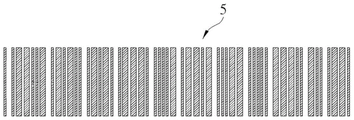
Fig. 9A is a schematic diagram of the target barcode 5.
Fig. 9B is a schematic diagram of a target image obtained by the barcode reader 3 capturing the target barcode 5.
FIG. 10 is a diagram illustrating a gray scale distribution of a target scan line.
Detailed Description
In order to further understand the objects, structures, features and functions of the present invention, the following embodiments are described in detail.
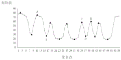
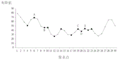
Referring to fig. 2A to 7, fig. 2A is a schematic diagram illustrating a use state of a sample barcode 4 scanned by a barcode reader 3 according to an embodiment of the present invention, FIG. 2B is a schematic diagram of a sample image obtained by scanning a sample barcode 4 by a barcode reader 3 according to an embodiment of the present invention, FIG. 3 is a functional block diagram of the barcode reader 3 in FIG. 2A, FIG. 4 is a flowchart of a barcode indication method according to an embodiment of the present invention for establishing a comparison table of barcode image characteristics and relative distances between the barcode reader 3 and the sample barcode 4, FIG. 5 is a diagram illustrating a gray scale distribution obtained when the predetermined distance between the barcode reader 3 and the sample barcode 4 is a relative middle distance, FIG. 6 is a diagram illustrating a gray scale distribution obtained when a predetermined distance between the barcode reader 3 and the sample barcode 4 is a relatively long distance, fig. 7 is a schematic diagram of a gray scale distribution obtained when the predetermined distance between the barcode reader 3 and the sample barcode 4 is a relatively short distance.
As shown in fig. 3, the barcode reader 3 of the present invention includes an image capturing unit 30, a light emitting unit 32, a processing unit 34, an alarm unit 36 and a memory unit 38, wherein the processing unit 34 is electrically connected to the image capturing unit 30, the light emitting unit 32, the alarm unit 36 and the memory unit 38. In practical applications, the image capturing unit 30 may be a Charge-coupled Device (CCD) sensor or a Complementary Metal-Oxide Semiconductor (CMOS) sensor; the light emitting unit 32 may be a light emitting diode or other light emitting components; the processing unit 34 may be a processor or controller having data processing functionality; the warning unit 36 may be a light source, a display, a speaker, a vibration motor, or a combination thereof; memory unit 38 may be a memory or other data storage device. Generally, the barcode reader 3 is further provided with software and hardware components necessary for operation, such as a circuit board, a power supply, an application program, a communication module, a lens, and the like, depending on the actual application.
According to the invention, the image characteristics of the sample bar code 4 are obtained by the bar code reader 3, and then the relative distance between the bar code reader 3 and the sample bar code 4 is estimated, so that the relative distance information required in decoding is provided, and the decoding success rate is effectively improved. Therefore, before decoding the barcode, the barcode indicating method of the present invention may first establish a comparison table of the barcode image characteristics and the relative distance between the barcode reader 3 and the sample barcode 4.
First, step S10 is performed to provide a sample barcode 4. In this embodiment, the code of the sample barcode 4 conforms to a specific coding rule. As shown in fig. 2A, the Code of the sample barcode 4 may conform to the Code 39, so that after decoding the sample barcode 4, the Code of "× 3A" may be obtained. Since there are regions corresponding to fixed start and stop symbols before and after the sample barcode 4, the present invention can use this special region to create a lookup table of barcode image characteristics and relative distances between the barcode reader 3 and the sample barcode 4. It should be noted that the encoding of the sample barcode 4 may also select other encoding rules according to actual requirements, and is not limited to the encoding rule of the Code 39.
Next, step S12 is executed to capture a plurality of sample images of the sample barcode 4 at a plurality of predetermined distances by the barcode reader 3, wherein a part of the predetermined distances belongs to a relatively long distance, a part of the predetermined distances belongs to a relatively medium distance (i.e. an effective decoding distance), and the rest of the predetermined distances belongs to a relatively short distance.
Next, step S14 is executed to set sample scan lines 40 in the first interval of each sample image. The sample scan line 40 may be set to a horizontal line on the sample image of the sample barcode 4, as shown in fig. 2B. It should be noted that the first interval is the special interval, i.e. the sample scan line 40 can be set in the special interval (corresponding to the fixed start and stop symbol "+") to improve the versatility; in addition, in the present invention, only the sample scan line 40 is set on the sample image to scan the sample image along the sample scan line 40 and obtain the gray scale distribution of the sample scan line 40, the sample scan line 40 is not directly drawn on the sample image, but the obtained gray scale distribution is affected if the sample scan line 40 actually exists on the sample image, so that the sample scan line 40 cannot be directly seen on the sample image in practice, and fig. 2B only marks the sample scan line 40 for easy understanding.
Next, step S16 is executed to analyze the relative relationship between at least two feature points on the gray-scale distribution of each sample scan line 40 according to the encoding rule to obtain at least one first predetermined feature parameter corresponding to a relatively long distance, at least one second predetermined feature parameter corresponding to a relatively medium distance, and at least one third predetermined feature parameter corresponding to a relatively short distance.
In this embodiment, fig. 5 shows a gray scale distribution obtained when the predetermined distance between the barcode reader 3 and the sample barcode 4 is a relatively middle distance, fig. 6 shows a gray scale distribution obtained when the predetermined distance between the barcode reader 3 and the sample barcode 4 is a relatively long distance, and fig. 7 shows a gray scale distribution obtained when the predetermined distance between the barcode reader 3 and the sample barcode 4 is a relatively short distance, in which a triangle and a square are a peak point and a valley point of the gray scale distribution, respectively.
The present invention can analyze two adjacent peak points a and B, two adjacent peak points C, E, and two adjacent valley points D and E as three sets of feature points as shown in fig. 5 to 7. It should be noted that, taking two adjacent peak points a and valley points B as an example, the relative positions of the gray scale distribution curves corresponding to the peak points a and the valley points B in fig. 5 are the same as the relative positions of the gray scale distribution curves corresponding to the peak points a and the valley points B in fig. 6, and the relative positions of the gray scale distribution curves corresponding to the peak points a and the valley points B in fig. 6 are the same as the relative positions of the gray scale distribution curves corresponding to the peak points a and the valley points B in fig. 7, that is, the peak points a in fig. 5 to 7 all correspond to the same interval of the sample barcode 4, and the valley points B in fig. 5 to 7 all correspond to the same interval of the sample barcode 4, so as to obtain the relative position relationship between the peak points a and the valley points B at different predetermined distances; the selection principle of the two adjacent peak points C, E and the two adjacent valley points D and E is the same as above, and will not be described herein again. Of course, the invention can also select two adjacent peaks and troughs, two adjacent peaks, two adjacent troughs, or a combination thereof as the feature points for analysis according to practical applications, and is not limited to the embodiments shown in fig. 5 to 7.
For example, the predetermined distance between the barcode reader 3 and the sample barcode 4 is defined as a relative middle distance when the distance is 7 cm, and the gray scale distribution shown in fig. 5 is obtained by the relative middle distance, wherein two adjacent peak points a and B are separated by a distance of 5 pixels, two adjacent peak points C, E are separated by a distance of 5 pixels, and the gray scale difference between two adjacent peak points D and E is 35. In addition, a predetermined distance between the barcode reader 3 and the sample barcode 4 is defined as a relative distance when the distance is 13 cm, and the gray scale distribution shown in fig. 6 is obtained by the relative distance, where two adjacent peak points a and B are separated by a distance of 3 pixels, two adjacent peak points C, E are separated by a distance of 1 pixel, and the gray scale difference between two adjacent peak points D and E is 7. Furthermore, a predetermined distance between the barcode reader 3 and the sample barcode 4 is defined as a relatively short distance when the distance is 4 cm, and the gray scale distribution shown in fig. 7 is obtained by the relatively short distance, where two adjacent peak points a and B are separated by 8 pixel distances, two adjacent peak points C, E are separated by 7 pixel distances, and the gray scale difference between two adjacent peak points D and E is 14. It should be noted that the pixel distance, the gray level difference value, or the combination thereof between two feature points can be selected as the relative relationship between two feature points according to practical applications, and the embodiment is not limited to the above.
After the barcode reader 3 captures a plurality of sample images of the sample barcode 4 at a plurality of different predetermined distances and the above analysis is performed on the gray scale distribution of the sample scan line 40 of each sample image, a comparison table of barcode image characteristics and the relative distances between the barcode reader 3 and the sample barcode 4 as shown in table 1 below is established, wherein the comparison table shown in table 1 is stored in the memory unit 38.
TABLE 1


Referring to fig. 8 to 10, fig. 8 is a flowchart of a barcode indicating method according to an embodiment of the present invention, fig. 9A is a schematic diagram of a target barcode 5, fig. 9B is a schematic diagram of a target image obtained by a barcode reader 3 capturing the target barcode 5, and fig. 10 is a schematic diagram of a gray scale distribution of a target scan line 50. After the comparison table of the barcode image features and the relative distances between the barcode reader 3 and the sample barcode 4 as shown in table 1 above is established, the target barcode 5 can be captured and decoded according to table 1. It should be noted that, since table 1 is established according to the encoding rule of Code 39, the target barcode 5 also needs to conform to the encoding rule of Code 39. In other words, the encoding rule of the target barcode 5 is required to conform to the encoding rule used to establish table 1. The present invention can generate a plurality of mapping tables shown in table 1 corresponding to different encoding rules through the above-mentioned manner, and store the plurality of mapping tables in the memory unit 38.
First, in step S30, the barcode reader 3 captures a target image of the target barcode 5, that is, the image capturing unit 30 of the barcode reader 3 captures the target image of the target barcode 5.
Next, in step S32, the processing unit 34 analyzes the target image to obtain image parameters. In this embodiment, the processing unit 34 may set the target scan line 50 before the second interval of the target image, as shown in fig. 9B, wherein the decoding of the first interval and the second interval is the same. It should be noted that the second interval is also the special interval, and the sample scan line 40 is set in the special interval, i.e. the interval corresponding to the fixed start and end symbols "", otherwise the reference property of table 1 will be lost. Of course, the setting of the scan line is not limited thereto, as long as the corresponding decoding of the section of the sample barcode set by the sample scan line and the section of the target barcode set by the target scan line is the same, which is determined by the designer according to the actual situation, and is not described herein again.
In addition, in the present invention, only the target scan line 50 is set on the target image to scan the target image along the target scan line 50 and obtain the gray scale distribution of the target scan line 50, the target scan line 50 is not directly drawn on the target image, but if the target scan line 50 actually exists on the target image, the obtained gray scale portion is affected, so that the target scan line 50 cannot be directly seen on the target image in practice, and fig. 9B only marks the target scan line 50 for easy understanding. Then, the processing unit 34 may analyze a relative relationship between at least two feature points on the gray-scale distribution of the target scan line 50 according to the encoding rule of the target barcode 5 to obtain an image parameter, wherein the image parameter includes at least one reference feature parameter. Since table 1 is established with two adjacent peak points a and B, two adjacent peak points C, E, and two adjacent valley points D and E shown in fig. 5 to 7 as three sets of feature points, the present invention can obtain three reference feature parameters according to the relative relationship (as shown in fig. 10) between two adjacent peak points a and B, two adjacent peak points C, E, and two adjacent valley points D and E on the gray scale distribution of the target scan line 50, that is, the pixel distance between two adjacent peak points a and B, the pixel distance between two adjacent peak points C, E, and the gray scale difference between two adjacent valley points D and E.
After the image parameters of the target image of the target barcode 5 are obtained in the above manner, step S34 is executed, and the processing unit determines whether the current distance between the barcode reader 3 and the target barcode 5 is the relative middle distance according to the image parameters. In this embodiment, when the reference characteristic parameter (i.e., the image parameter) obtained according to the target barcode 5 matches the first predetermined characteristic parameter in table 1, the processing unit 34 can determine that the current distance between the barcode reader 3 and the target barcode 5 is a relatively long distance; when the reference characteristic parameter (i.e., the image parameter) obtained according to the target barcode 5 matches the second predetermined characteristic parameter in table 1, the processing unit 34 may determine that the current distance between the barcode reader 3 and the target barcode 5 is a relative middle distance, i.e., an effective decoding distance; when the reference characteristic parameter (i.e., the image parameter) obtained from the target barcode 5 matches the third predetermined characteristic parameter in table 1, the processing unit 34 determines that the current distance between the barcode reader 3 and the target barcode 5 is relatively close.
When the processing unit 34 determines that the current distance between the barcode reader 3 and the target barcode 5 is the relative middle distance, i.e. the effective decoding distance, step S36 is executed, and the processing unit 34 controls the light-emitting unit 32 to emit the indication light onto the target barcode 5. In this embodiment, when the light-emitting unit 32 emits the indicating light on the target barcode 5, the processing unit 34 can decode the target image of the target barcode 5 at the same time. In another embodiment, when the light-emitting unit 32 emits the indicating light onto the target barcode 5, the processing unit 34 may decode the target image of the target barcode 5 after the user further triggers the switch on the barcode reader 3. Since the target barcode 5 is located within the relative middle distance range, the image capturing unit 30 captures an image of the target barcode 5. In other words, even if other barcodes exist near the target barcode 5, when the user sees the indication light to strike the target barcode 5, it is determined that the barcode reader 3 must decode the target barcode 5. Therefore, the decoding success rate of the target bar code 5 can be effectively improved.
On the other hand, when the processing unit 34 determines that the current distance between the barcode reader 3 and the target barcode 5 is not the relative middle distance (e.g., the relative long distance or the relative short distance), step S38 is executed in which the processing unit 34 controls the warning unit 36 to issue a warning message to prompt the user to adjust the current distance between the barcode reader 3 and the target barcode 5 to the relative middle distance. In this embodiment, the warning message may be light, image, sound, vibration or a combination thereof, depending on the application. In addition, the present invention can also use the light emitting unit 32 as a warning unit, in which case, the warning unit 36 can be omitted.
For example, when the current distance between the barcode reader 3 and the target barcode 5 is relatively far (i.e. the barcode reader 3 is too far away from the target barcode 5), the present invention can prompt the user to approach the barcode reader 3 to the target barcode 5 for image capture in a fast flashing manner. On the contrary, when the current distance between the barcode reader 3 and the target barcode 5 is relatively close (i.e. the barcode reader 3 is too close to the target barcode 5), the present invention can prompt the user to take an image by keeping the barcode reader 3 away from the target barcode 5 in a slow flashing manner. Of course, the present invention can also directly display the "too far", "too near" or other characters, symbols or images to prompt the user. In other words, the presentation manner of the warning message can be determined according to the practical application, and is not limited to the above embodiments.
In another embodiment, the image parameter obtained in the step S32 may also be an image sharpness. In other words, the present invention can analyze the target image of the target barcode 5 by using an image processing technique to obtain the image resolution of the target image, and the image resolution of the target image is used as the image parameter. When the image definition falls within the predetermined definition range, the processing unit 34 may determine that the current distance between the barcode reader 3 and the target barcode 5 is a relative middle distance, and when the image definition falls outside the predetermined definition range, the processing unit 34 may determine that the current distance between the barcode reader 3 and the target barcode 5 is not a relative middle distance. It should be noted that the corresponding relationship between the predetermined definition range and the relative middle distance can be determined according to practical applications.
In summary, when the barcode reader of the present invention is used to read a barcode, the light-emitting unit is controlled to emit an indication light onto the target barcode only when the present distance between the barcode reader and the target barcode is determined to be a relative middle distance. At this time, the barcode reader decodes the target image of the target barcode. Since the target bar code is located within the relative middle distance range, the image capturing unit captures an image of the target bar code. In other words, even if other barcodes exist near the target barcode, when the user sees the pointing light to strike the target barcode, it can be determined that the barcode reader must decode the target barcode. Therefore, the decoding success rate of the target bar code can be effectively improved. In addition, when the current distance between the barcode reader and the target barcode is not a relatively middle distance (e.g., a relatively long distance or a relatively short distance), the present invention may send an alert message from the barcode reader to prompt the user to adjust the current distance between the barcode reader and the target barcode to be the relatively middle distance. Therefore, the number of times that the user repeatedly moves the bar code reader can be reduced, and the decoding efficiency is improved.
The present invention has been described in relation to the above embodiments, which are only exemplary of the implementation of the present invention. It should be noted that the disclosed embodiments do not limit the scope of the invention. Rather, it is intended that all such modifications and variations be included within the spirit and scope of this invention.
Claims (10)
1. A bar code indicating method, comprising the steps of:
capturing a target image of a target bar code by a bar code reader;
analyzing the target image to obtain image parameters;
judging whether the current distance between the bar code reader and the target bar code is an effective decoding distance or not according to the image parameters; and
when the current distance is judged to be the effective decoding distance, the bar code reader sends out indicating light to the target bar code; when the current distance is judged to be relatively long, a first warning message is sent from the bar code reader; when the current distance is judged to be relatively close, a second warning message is sent from the bar code reader; wherein the second alert message is different from the first alert message;
wherein, the step of analyzing the target image and determining whether the current distance is an effective decoding distance specifically comprises the following steps:
setting a target scanning line on a first interval of the target image;
analyzing the relative relation between at least two characteristic points on the gray scale distribution of the target scanning line according to the coding rule to obtain the image parameter, wherein the image parameter comprises at least one reference characteristic parameter;
when the at least one reference characteristic parameter is consistent with the corresponding at least one first preset characteristic parameter, judging that the current distance is a relatively long distance;
when the at least one reference characteristic parameter is consistent with at least one corresponding second preset characteristic parameter, judging that the current distance is the effective decoding distance; and
and when the at least one reference characteristic parameter is consistent with the corresponding at least one third preset characteristic parameter, judging that the current distance is a relatively short distance.
2. The bar code indicating method of claim 1 wherein the image parameters further include image sharpness, the bar code indicating method further comprising the steps of:
when the image definition falls into a preset definition range, judging that the current distance is the effective decoding distance; and
and when the image definition falls outside the preset definition range, judging that the current distance is not the effective decoding distance.
3. The bar code indicating method of claim 1, further comprising the steps of:
capturing a plurality of sample images of a sample bar code at a plurality of preset distances by using the bar code reader, wherein the plurality of preset distances belong to the relatively long distance, part of the preset distances belong to the effective decoding distance, and the rest part of the preset distances belong to the relatively short distance;
setting a sample scanning line on a second interval of each sample image, wherein the decoding of the first interval and the second interval is the same; and
analyzing the relative relationship between at least two feature points on the gray scale distribution of each sample scanning line according to the encoding rule to obtain the at least one first predetermined feature parameter corresponding to the relatively long distance, the at least one second predetermined feature parameter corresponding to the effective decoding distance, and the at least one third predetermined feature parameter corresponding to the relatively short distance.
4. The barcode indication method according to claim 1 or 3, wherein the relative relationship between the at least two feature points is a pixel distance or a combination of the pixel distance and a gray level difference value.
5. A bar code indicating method according to claim 1 or 3 wherein the at least two characteristic points are two adjacent peak and valley points, two adjacent peak points, two adjacent valley points or a combination thereof.
6. A barcode reader, comprising:
the image capturing unit captures a target image of the target bar code;
a light emitting unit;
a warning unit; and
the processing unit is electrically connected with the image acquisition unit, the warning unit and the light-emitting unit, analyzes the target image to obtain image parameters, and judges whether the current distance between the bar code reader and the target bar code is an effective decoding distance or not according to the image parameters; when the processing unit judges that the current distance is the effective decoding distance, the processing unit controls the light-emitting unit to emit indicating light on the target bar code; when the processing unit judges that the current distance is relatively long, the processing unit controls the warning unit to send out a first warning message; when the processing unit judges that the current distance is relatively short, the processing unit controls the warning unit to send out a second warning message; wherein the second alert message is different from the first alert message;
the processing unit sets a target scanning line on a first interval of the target image, analyzes the relative relation between at least two characteristic points on the gray scale distribution of the target scanning line according to a coding rule to obtain the image parameter, and the image parameter comprises at least one reference characteristic parameter; when the at least one reference characteristic parameter is consistent with the corresponding at least one first preset characteristic parameter, the processing unit judges that the current distance is a relatively long distance; when the at least one reference characteristic parameter is consistent with at least one corresponding second preset characteristic parameter, the processing unit judges that the current distance is the effective decoding distance; when the at least one reference characteristic parameter is consistent with the corresponding at least one third preset characteristic parameter, the processing unit judges that the current distance is a relatively short distance.
7. The barcode reader of claim 6, wherein the image parameters further include an image sharpness, the processing unit determines the current distance as the valid decoding distance when the image sharpness falls within a predetermined sharpness range, and the processing unit determines the current distance as not the valid decoding distance when the image sharpness falls outside the predetermined sharpness range.
8. The barcode reader of claim 7, further comprising a memory unit electrically connected to the processing unit, the memory unit storing a look-up table recording the at least one first predetermined characteristic parameter corresponding to the relatively long distance, the at least one second predetermined characteristic parameter corresponding to the effective decoding distance, and the at least one third predetermined characteristic parameter corresponding to the relatively short distance.
9. The barcode reader of claim 7, wherein the relative relationship between the at least two feature points is a pixel distance or a combination of a pixel distance and a gray level difference value.
10. The barcode reader of claim 7, wherein the at least two feature points are two adjacent peak and valley points, two adjacent peak points, two adjacent valley points, or a combination thereof.
Priority Applications (1)
| Application Number | Priority Date | Filing Date | Title |
|---|---|---|---|
| CN201610647272.XA CN106295455B (en) | 2016-08-09 | 2016-08-09 | Bar code indicating method and bar code reader |
Applications Claiming Priority (1)
| Application Number | Priority Date | Filing Date | Title |
|---|---|---|---|
| CN201610647272.XA CN106295455B (en) | 2016-08-09 | 2016-08-09 | Bar code indicating method and bar code reader |
Publications (2)
| Publication Number | Publication Date |
|---|---|
| CN106295455A CN106295455A (en) | 2017-01-04 |
| CN106295455B true CN106295455B (en) | 2021-08-03 |
Family
ID=57666798
Family Applications (1)
| Application Number | Title | Priority Date | Filing Date |
|---|---|---|---|
| CN201610647272.XA Expired - Fee Related CN106295455B (en) | 2016-08-09 | 2016-08-09 | Bar code indicating method and bar code reader |
Country Status (1)
| Country | Link |
|---|---|
| CN (1) | CN106295455B (en) |
Families Citing this family (3)
| Publication number | Priority date | Publication date | Assignee | Title |
|---|---|---|---|---|
| CN109670362A (en) * | 2017-10-16 | 2019-04-23 | 上海商米科技有限公司 | Bar code scanning method and device |
| CN109615360A (en) * | 2018-09-29 | 2019-04-12 | 阿里巴巴集团控股有限公司 | A kind of graphic coding display method and device |
| CN115906882A (en) * | 2022-12-16 | 2023-04-04 | 苏州斯普锐智能系统股份有限公司 | Installation system and installation method of code reading equipment |
Citations (3)
| Publication number | Priority date | Publication date | Assignee | Title |
|---|---|---|---|---|
| CN102034072A (en) * | 2009-09-25 | 2011-04-27 | 神基科技股份有限公司 | Bar code image identification method |
| CN102096797A (en) * | 2011-01-18 | 2011-06-15 | 深圳市民德电子科技有限公司 | Position prompting device and method for read bar code and bar code reading equipment |
| CN103336938A (en) * | 2013-06-05 | 2013-10-02 | 华南理工大学 | Recognition method based one-dimensional bar code image |
Family Cites Families (5)
| Publication number | Priority date | Publication date | Assignee | Title |
|---|---|---|---|---|
| JP2003168071A (en) * | 2001-11-30 | 2003-06-13 | Sanyo Electric Co Ltd | How to read 2D barcodes |
| CN101419481A (en) * | 2007-10-25 | 2009-04-29 | 达方电子股份有限公司 | Posture reminding method and device |
| CN102480587A (en) * | 2010-11-23 | 2012-05-30 | 英业达股份有限公司 | Network camera device and operating method thereof |
| CN103491307B (en) * | 2013-10-07 | 2018-12-11 | 厦门美图网科技有限公司 | A kind of intelligent self-timer method of rear camera |
| CN105279490A (en) * | 2015-10-21 | 2016-01-27 | 北京无线电计量测试研究所 | Man-machine interaction type iris image automatic acquisition apparatus |
-
2016
- 2016-08-09 CN CN201610647272.XA patent/CN106295455B/en not_active Expired - Fee Related
Patent Citations (3)
| Publication number | Priority date | Publication date | Assignee | Title |
|---|---|---|---|---|
| CN102034072A (en) * | 2009-09-25 | 2011-04-27 | 神基科技股份有限公司 | Bar code image identification method |
| CN102096797A (en) * | 2011-01-18 | 2011-06-15 | 深圳市民德电子科技有限公司 | Position prompting device and method for read bar code and bar code reading equipment |
| CN103336938A (en) * | 2013-06-05 | 2013-10-02 | 华南理工大学 | Recognition method based one-dimensional bar code image |
Also Published As
| Publication number | Publication date |
|---|---|
| CN106295455A (en) | 2017-01-04 |
Similar Documents
| Publication | Publication Date | Title |
|---|---|---|
| EP3040906B1 (en) | Visual feedback for code readers | |
| US10013591B2 (en) | Code symbol reading system having adaptive autofocus | |
| US9443123B2 (en) | System and method for indicia verification | |
| US8167209B2 (en) | Increasing imaging quality of a bar code reader | |
| EP2507741B1 (en) | Imaging-based scanner including border searching for image acquisition | |
| CN107392069B (en) | Indicia reading apparatus and method for decoding decodable indicia using stereoscopic imaging | |
| CN106295455B (en) | Bar code indicating method and bar code reader | |
| US20060091216A1 (en) | Self-optimizing symbology reader | |
| KR102641301B1 (en) | Systems and methods for user selection of barcode scanning range | |
| US9524411B2 (en) | User-customizable data capture terminal for and method of imaging and processing a plurality of target data on one or more targets | |
| US9710688B2 (en) | Stereoscopic information code and stereoscopic information code reading device | |
| JP5413006B2 (en) | Portable terminal device and program | |
| TWI623884B (en) | Barcode indicating method and barcode reader | |
| CN114444531B (en) | Method and system for collecting data for training machine learning (ML) models | |
| JP6638614B2 (en) | Optical information reader | |
| JP4378491B2 (en) | Code image output device | |
| TWI623882B (en) | Barcode capturing method and barcode reader | |
| JP4873312B2 (en) | Optical information reader |
Legal Events
| Date | Code | Title | Description |
|---|---|---|---|
| C06 | Publication | ||
| PB01 | Publication | ||
| C10 | Entry into substantive examination | ||
| SE01 | Entry into force of request for substantive examination | ||
| GR01 | Patent grant | ||
| GR01 | Patent grant | ||
| CF01 | Termination of patent right due to non-payment of annual fee |
Granted publication date: 20210803 |
|
| CF01 | Termination of patent right due to non-payment of annual fee |