CN106236257B - Alignment of coronary sinus catheter images - Google Patents
Alignment of coronary sinus catheter images Download PDFInfo
- Publication number
- CN106236257B CN106236257B CN201610390607.4A CN201610390607A CN106236257B CN 106236257 B CN106236257 B CN 106236257B CN 201610390607 A CN201610390607 A CN 201610390607A CN 106236257 B CN106236257 B CN 106236257B
- Authority
- CN
- China
- Prior art keywords
- heart
- coronary sinus
- model
- image data
- catheter
- Prior art date
- Legal status (The legal status is an assumption and is not a legal conclusion. Google has not performed a legal analysis and makes no representation as to the accuracy of the status listed.)
- Active
Links
Images


Classifications
-
- A—HUMAN NECESSITIES
- A61—MEDICAL OR VETERINARY SCIENCE; HYGIENE
- A61B—DIAGNOSIS; SURGERY; IDENTIFICATION
- A61B5/00—Measuring for diagnostic purposes; Identification of persons
- A61B5/0033—Features or image-related aspects of imaging apparatus classified in A61B5/00, e.g. for MRI, optical tomography or impedance tomography apparatus; arrangements of imaging apparatus in a room
- A61B5/004—Features or image-related aspects of imaging apparatus classified in A61B5/00, e.g. for MRI, optical tomography or impedance tomography apparatus; arrangements of imaging apparatus in a room adapted for image acquisition of a particular organ or body part
- A61B5/0044—Features or image-related aspects of imaging apparatus classified in A61B5/00, e.g. for MRI, optical tomography or impedance tomography apparatus; arrangements of imaging apparatus in a room adapted for image acquisition of a particular organ or body part for the heart
-
- A—HUMAN NECESSITIES
- A61—MEDICAL OR VETERINARY SCIENCE; HYGIENE
- A61B—DIAGNOSIS; SURGERY; IDENTIFICATION
- A61B6/00—Apparatus for radiation diagnosis, e.g. combined with radiation therapy equipment
- A61B6/12—Devices for detecting or locating foreign bodies
-
- A—HUMAN NECESSITIES
- A61—MEDICAL OR VETERINARY SCIENCE; HYGIENE
- A61B—DIAGNOSIS; SURGERY; IDENTIFICATION
- A61B6/00—Apparatus for radiation diagnosis, e.g. combined with radiation therapy equipment
- A61B6/52—Devices using data or image processing specially adapted for radiation diagnosis
- A61B6/5211—Devices using data or image processing specially adapted for radiation diagnosis involving processing of medical diagnostic data
- A61B6/5229—Devices using data or image processing specially adapted for radiation diagnosis involving processing of medical diagnostic data combining image data of a patient, e.g. combining a functional image with an anatomical image
- A61B6/5235—Devices using data or image processing specially adapted for radiation diagnosis involving processing of medical diagnostic data combining image data of a patient, e.g. combining a functional image with an anatomical image combining images from the same or different ionising radiation imaging techniques, e.g. PET and CT
-
- A—HUMAN NECESSITIES
- A61—MEDICAL OR VETERINARY SCIENCE; HYGIENE
- A61B—DIAGNOSIS; SURGERY; IDENTIFICATION
- A61B5/00—Measuring for diagnostic purposes; Identification of persons
- A61B5/0059—Measuring for diagnostic purposes; Identification of persons using light, e.g. diagnosis by transillumination, diascopy, fluorescence
- A61B5/0071—Measuring for diagnostic purposes; Identification of persons using light, e.g. diagnosis by transillumination, diascopy, fluorescence by measuring fluorescence emission
-
- A—HUMAN NECESSITIES
- A61—MEDICAL OR VETERINARY SCIENCE; HYGIENE
- A61B—DIAGNOSIS; SURGERY; IDENTIFICATION
- A61B5/00—Measuring for diagnostic purposes; Identification of persons
- A61B5/0059—Measuring for diagnostic purposes; Identification of persons using light, e.g. diagnosis by transillumination, diascopy, fluorescence
- A61B5/0082—Measuring for diagnostic purposes; Identification of persons using light, e.g. diagnosis by transillumination, diascopy, fluorescence adapted for particular medical purposes
- A61B5/0084—Measuring for diagnostic purposes; Identification of persons using light, e.g. diagnosis by transillumination, diascopy, fluorescence adapted for particular medical purposes for introduction into the body, e.g. by catheters
-
- A—HUMAN NECESSITIES
- A61—MEDICAL OR VETERINARY SCIENCE; HYGIENE
- A61B—DIAGNOSIS; SURGERY; IDENTIFICATION
- A61B5/00—Measuring for diagnostic purposes; Identification of persons
- A61B5/06—Devices, other than using radiation, for detecting or locating foreign bodies ; determining position of probes within or on the body of the patient
- A61B5/065—Determining position of the probe employing exclusively positioning means located on or in the probe, e.g. using position sensors arranged on the probe
- A61B5/066—Superposing sensor position on an image of the patient, e.g. obtained by ultrasound or x-ray imaging
-
- A—HUMAN NECESSITIES
- A61—MEDICAL OR VETERINARY SCIENCE; HYGIENE
- A61B—DIAGNOSIS; SURGERY; IDENTIFICATION
- A61B6/00—Apparatus for radiation diagnosis, e.g. combined with radiation therapy equipment
-
- A—HUMAN NECESSITIES
- A61—MEDICAL OR VETERINARY SCIENCE; HYGIENE
- A61B—DIAGNOSIS; SURGERY; IDENTIFICATION
- A61B6/00—Apparatus for radiation diagnosis, e.g. combined with radiation therapy equipment
- A61B6/02—Devices for diagnosis sequentially in different planes; Stereoscopic radiation diagnosis
- A61B6/03—Computerised tomographs
- A61B6/032—Transmission computed tomography [CT]
-
- A—HUMAN NECESSITIES
- A61—MEDICAL OR VETERINARY SCIENCE; HYGIENE
- A61B—DIAGNOSIS; SURGERY; IDENTIFICATION
- A61B6/00—Apparatus for radiation diagnosis, e.g. combined with radiation therapy equipment
- A61B6/46—Apparatus for radiation diagnosis, e.g. combined with radiation therapy equipment with special arrangements for interfacing with the operator or the patient
- A61B6/461—Displaying means of special interest
- A61B6/466—Displaying means of special interest adapted to display 3D data
-
- A—HUMAN NECESSITIES
- A61—MEDICAL OR VETERINARY SCIENCE; HYGIENE
- A61B—DIAGNOSIS; SURGERY; IDENTIFICATION
- A61B6/00—Apparatus for radiation diagnosis, e.g. combined with radiation therapy equipment
- A61B6/50—Clinical applications
- A61B6/503—Clinical applications involving diagnosis of heart
-
- A—HUMAN NECESSITIES
- A61—MEDICAL OR VETERINARY SCIENCE; HYGIENE
- A61B—DIAGNOSIS; SURGERY; IDENTIFICATION
- A61B6/00—Apparatus for radiation diagnosis, e.g. combined with radiation therapy equipment
- A61B6/52—Devices using data or image processing specially adapted for radiation diagnosis
- A61B6/5211—Devices using data or image processing specially adapted for radiation diagnosis involving processing of medical diagnostic data
- A61B6/5229—Devices using data or image processing specially adapted for radiation diagnosis involving processing of medical diagnostic data combining image data of a patient, e.g. combining a functional image with an anatomical image
- A61B6/5247—Devices using data or image processing specially adapted for radiation diagnosis involving processing of medical diagnostic data combining image data of a patient, e.g. combining a functional image with an anatomical image combining images from an ionising-radiation diagnostic technique and a non-ionising radiation diagnostic technique, e.g. X-ray and ultrasound
-
- A—HUMAN NECESSITIES
- A61—MEDICAL OR VETERINARY SCIENCE; HYGIENE
- A61B—DIAGNOSIS; SURGERY; IDENTIFICATION
- A61B90/00—Instruments, implements or accessories specially adapted for surgery or diagnosis and not covered by any of the groups A61B1/00 - A61B50/00, e.g. for luxation treatment or for protecting wound edges
- A61B90/36—Image-producing devices or illumination devices not otherwise provided for
-
- G—PHYSICS
- G06—COMPUTING; CALCULATING OR COUNTING
- G06T—IMAGE DATA PROCESSING OR GENERATION, IN GENERAL
- G06T11/00—2D [Two Dimensional] image generation
- G06T11/003—Reconstruction from projections, e.g. tomography
- G06T11/005—Specific pre-processing for tomographic reconstruction, e.g. calibration, source positioning, rebinning, scatter correction, retrospective gating
-
- G—PHYSICS
- G06—COMPUTING; CALCULATING OR COUNTING
- G06T—IMAGE DATA PROCESSING OR GENERATION, IN GENERAL
- G06T15/00—3D [Three Dimensional] image rendering
- G06T15/08—Volume rendering
-
- G—PHYSICS
- G06—COMPUTING; CALCULATING OR COUNTING
- G06T—IMAGE DATA PROCESSING OR GENERATION, IN GENERAL
- G06T7/00—Image analysis
-
- G—PHYSICS
- G06—COMPUTING; CALCULATING OR COUNTING
- G06T—IMAGE DATA PROCESSING OR GENERATION, IN GENERAL
- G06T7/00—Image analysis
- G06T7/0002—Inspection of images, e.g. flaw detection
- G06T7/0012—Biomedical image inspection
-
- G—PHYSICS
- G06—COMPUTING; CALCULATING OR COUNTING
- G06T—IMAGE DATA PROCESSING OR GENERATION, IN GENERAL
- G06T7/00—Image analysis
- G06T7/30—Determination of transform parameters for the alignment of images, i.e. image registration
- G06T7/33—Determination of transform parameters for the alignment of images, i.e. image registration using feature-based methods
-
- A—HUMAN NECESSITIES
- A61—MEDICAL OR VETERINARY SCIENCE; HYGIENE
- A61B—DIAGNOSIS; SURGERY; IDENTIFICATION
- A61B34/00—Computer-aided surgery; Manipulators or robots specially adapted for use in surgery
- A61B34/20—Surgical navigation systems; Devices for tracking or guiding surgical instruments, e.g. for frameless stereotaxis
- A61B2034/2046—Tracking techniques
- A61B2034/2051—Electromagnetic tracking systems
-
- A—HUMAN NECESSITIES
- A61—MEDICAL OR VETERINARY SCIENCE; HYGIENE
- A61B—DIAGNOSIS; SURGERY; IDENTIFICATION
- A61B90/00—Instruments, implements or accessories specially adapted for surgery or diagnosis and not covered by any of the groups A61B1/00 - A61B50/00, e.g. for luxation treatment or for protecting wound edges
- A61B90/36—Image-producing devices or illumination devices not otherwise provided for
- A61B2090/364—Correlation of different images or relation of image positions in respect to the body
-
- A—HUMAN NECESSITIES
- A61—MEDICAL OR VETERINARY SCIENCE; HYGIENE
- A61B—DIAGNOSIS; SURGERY; IDENTIFICATION
- A61B90/00—Instruments, implements or accessories specially adapted for surgery or diagnosis and not covered by any of the groups A61B1/00 - A61B50/00, e.g. for luxation treatment or for protecting wound edges
- A61B90/36—Image-producing devices or illumination devices not otherwise provided for
- A61B90/37—Surgical systems with images on a monitor during operation
- A61B2090/376—Surgical systems with images on a monitor during operation using X-rays, e.g. fluoroscopy
-
- A—HUMAN NECESSITIES
- A61—MEDICAL OR VETERINARY SCIENCE; HYGIENE
- A61B—DIAGNOSIS; SURGERY; IDENTIFICATION
- A61B5/00—Measuring for diagnostic purposes; Identification of persons
- A61B5/05—Detecting, measuring or recording for diagnosis by means of electric currents or magnetic fields; Measuring using microwaves or radio waves
- A61B5/055—Detecting, measuring or recording for diagnosis by means of electric currents or magnetic fields; Measuring using microwaves or radio waves involving electronic [EMR] or nuclear [NMR] magnetic resonance, e.g. magnetic resonance imaging
-
- G—PHYSICS
- G06—COMPUTING; CALCULATING OR COUNTING
- G06T—IMAGE DATA PROCESSING OR GENERATION, IN GENERAL
- G06T2207/00—Indexing scheme for image analysis or image enhancement
- G06T2207/10—Image acquisition modality
- G06T2207/10064—Fluorescence image
-
- G—PHYSICS
- G06—COMPUTING; CALCULATING OR COUNTING
- G06T—IMAGE DATA PROCESSING OR GENERATION, IN GENERAL
- G06T2207/00—Indexing scheme for image analysis or image enhancement
- G06T2207/10—Image acquisition modality
- G06T2207/10072—Tomographic images
- G06T2207/10081—Computed x-ray tomography [CT]
-
- G—PHYSICS
- G06—COMPUTING; CALCULATING OR COUNTING
- G06T—IMAGE DATA PROCESSING OR GENERATION, IN GENERAL
- G06T2207/00—Indexing scheme for image analysis or image enhancement
- G06T2207/10—Image acquisition modality
- G06T2207/10072—Tomographic images
- G06T2207/10088—Magnetic resonance imaging [MRI]
-
- G—PHYSICS
- G06—COMPUTING; CALCULATING OR COUNTING
- G06T—IMAGE DATA PROCESSING OR GENERATION, IN GENERAL
- G06T2207/00—Indexing scheme for image analysis or image enhancement
- G06T2207/10—Image acquisition modality
- G06T2207/10116—X-ray image
- G06T2207/10121—Fluoroscopy
-
- G—PHYSICS
- G06—COMPUTING; CALCULATING OR COUNTING
- G06T—IMAGE DATA PROCESSING OR GENERATION, IN GENERAL
- G06T2207/00—Indexing scheme for image analysis or image enhancement
- G06T2207/30—Subject of image; Context of image processing
- G06T2207/30004—Biomedical image processing
- G06T2207/30048—Heart; Cardiac
Abstract
The invention discloses a cardiac catheterization, which is performed by: importing image data of a heart of a living subject into an image processing computer system, representing the image data in a first coordinate space as a first model of the heart and the coronary sinus, and introducing a probe into the coronary sinus. A second model of the coronary sinus is then prepared in a second coordinate space using fluoroscopic image data of the probe, and the first model is transformed into the second coordinate space by placing the coronary sinus of the second model in alignment with the coronary sinus of the first model.
Description
Background
Technical Field
The present invention relates to cardiac physiology. More particularly, the invention relates to the assessment of electrical propagation in the heart.
Description of related art
The meanings of certain acronyms and abbreviations used herein are given in table 1.
TABLE 1 acronyms and abbreviations
| CS | Coronary sinus |
| LAO | Left front inclined position |
| RAO | Right oblique position |
| CT | Computed tomography |
| MRI | Magnetic resonance imaging |
Cardiac arrhythmias such as atrial fibrillation are a significant cause of morbidity and mortality. Commonly assigned U.S. patent 5,546,951 and U.S. patent 6,690,963 (both to Ben Haim), and PCT application WO 96/05768, both incorporated herein by reference, disclose methods for sensing electrical properties, such as local activation time, of cardiac tissue as a function of precise location within the heart. Data is acquired using one or more catheters having electrical and position sensors in their distal tips, which are advanced into the heart. Methods of creating a map of the electrical activity of the heart based on these data are disclosed in commonly assigned U.S. Pat. No. 6,226,542 and U.S. Pat. No. 6,301,496 (both to Reisfeld), which are incorporated herein by reference. As noted in these patents, the location and electrical activity is typically initially measured at about 10 to about 20 points on the inner surface of the heart. These data points are then typically sufficient to generate a preliminary reconstruction or map of the heart surface. The preliminary map is often combined with data acquired at additional points to generate a more comprehensive map of the electrical activity of the heart. Indeed, in a clinical setting, it is not uncommon to accumulate data at 100 or more sites to generate a detailed, comprehensive map of ventricular electrical activity. The generated detailed map can then be used as a basis for deciding on a course of therapeutic action (e.g., tissue ablation) to alter the propagation of electrical activity of the heart and restore a normal heart rhythm.
A catheter containing a position sensor can be used to determine the trajectory of points on the surface of the heart. These trajectories can be used to infer motion characteristics, such as the contractility of tissue. As disclosed in U.S. patent 5,738,096 to Ben Haim, which is incorporated herein by reference in its entirety, when trajectory information is sampled at a sufficient number of points in the heart, a map depicting such motion characteristics may be constructed.
Electrical activity at a point in the heart is typically measured by advancing a multi-electrode catheter to measure electrical activity simultaneously at multiple points in the ventricle. Recordings derived from time-varying potentials measured by one or more electrodes are called electrograms. The electrogram may be measured by a unipolar lead or a bipolar lead and used, for example, to determine the onset of electrical propagation at a point, which is referred to as a local activation time.
Currently, a large amount of anatomical and functional data is collected in catheter-based cardiac surgery. Maintaining this data in alignment with the actual position of the patient's heart and understanding the catheter's relationship to the anatomy are both critical to the success of the procedure. In one approach, the catheter is aligned with an image acquired by another modality.
An example of this approach is suggested in U.S. patent 7,720,520 to Willis. A reference catheter or reference element is placed in contact with the anatomical body. A reference element or a reference catheter is used to locate a physical structure within the navigational coordinate system. An image reference corresponding to the physical structure within the image coordinates is located. The positioning of the image reference may be done, for example, by displaying the medical image and electronically marking the displayed image reference, or by automatically positioning the image data corresponding to the image reference. The navigation coordinate system and the image coordinate system are then aligned based on the positioning of the physical structure within the navigation coordinate system and the positioning of the image fiducial within the image coordinate system, which allows the graphical information to be merged with the medical image data.
Disclosure of Invention
According to disclosed embodiments of the invention, a reconstruction of the heart is prepared from cardiac image data (such as CT data or MRI data) prior to catheterization. The reconstruction takes into account the motion of the cardiac structure (such as the coronary sinus) due to the motion of the heart and the patient. With this reconstruction, the coronary sinus is catheterized and reconstructed with fluoroscopic image data. The reconstruction of the coronary sinus is placed in registration with the reconstruction of the heart so that the coordinate space of the resulting image coincides with the coordinate space of a functional electro-anatomical image of the heart (e.g., a CARTO map) that may be displayed or generated. The cardiac structure of interest may then be identified on the functional electroanatomical image by the operator.
According to an embodiment of the present invention, there is provided a method performed by: the method includes importing image data of a heart of a living subject into an image processing computer system, representing the image data in a first coordinate space as a first model of the heart and a coronary sinus, and introducing a probe into the coronary sinus. The method is then further performed by: acquiring fluoroscopic image data of the probe, preparing a second model of the coronary sinus in a second coordinate space using the fluoroscopic image data, and transforming the first model into the second coordinate space by placing the coronary sinus of the second model in alignment with the coronary sinus of the first model.
The image data is obtained by computer tomography or magnetic resonance imaging of the heart.
According to one aspect of the method, the first model is a 3-dimensional model.
According to another aspect of the method, preparing the second model includes reconstructing a 2-dimensional path of the probe.
According to additional aspects of the method, preparing the second model includes estimating a 3-dimensional path of the probe from the 2-dimensional path.
Another aspect of the method includes positioning a cardiac structure in the transformed first model in a second coordinate space.
There is also provided, in accordance with an embodiment of the present invention, apparatus including a cardiac catheter introducible into a coronary sinus of a heart of a living subject, a display, and a processor. A processor cooperates with the fluoroscopic imaging apparatus for performing a method by: the method includes importing image data of a heart into an image processing computer system, representing the image data in a first coordinate space as a first model of the heart and a coronary sinus, and introducing a probe into the coronary sinus. The method is then further performed by: acquiring fluoroscopic image data of the probe, preparing a second model of the coronary sinus in a second coordinate space using the fluoroscopic image data, and transforming the first model into the second coordinate space by placing the coronary sinus of the second model in alignment with the coronary sinus of the first model.
Drawings
For a better understanding of the present invention, reference is made to the detailed description of the invention, by way of example, which is to be read in connection with the following drawings, wherein like elements are given like reference numerals, and wherein:
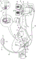
FIG. 1 is a perspective illustration of a system for performing cardiac catheterization procedures, constructed and operative in accordance with a disclosed embodiment of the present invention;
FIG. 2 is a flow chart of a method of aligning images of a heart using a coronary sinus catheter according to an embodiment of the present invention; and is
FIG. 3 is a composite image illustrating stages in a process of coronary sinus reconstruction applied to a 3-dimensional model of the heart, according to an embodiment of the invention.
Detailed Description
In the following description, numerous specific details are set forth in order to provide a thorough understanding of the various principles of the invention. It will be apparent, however, to one skilled in the art that not all of these details are required in order to practice the present invention. In this example, well-known circuits, control logic, and the details of computer program instructions for conventional algorithms and processes have not been shown in detail in order not to unnecessarily obscure the general concepts.
Aspects of the present invention may be embodied in software programming code that is typically maintained in a non-transitory storage device such as a computer readable medium. In a client/server environment, such software programming code may be stored on a client or server. The software programming code may be embodied on any of a variety of known non-transitory media such as USB memory, a hard drive, electronic media, or CD-ROM for use with a data processing system. The code may be distributed on such media, or may be distributed to users from the memory or storage of one computer system over a network of some type to storage on other computer systems for use by users of such other systems.
Embodiments of the present invention allow for identification of cardiac structures in a medical procedure. When the position of the coronary sinus is accurately known based on fluoroscopy of the coronary sinus catheter, its position may be related to the position of other parts of the heart, provided that a common coordinate system exists to locate the other parts. Embodiments of the present invention place the coronary sinus as determined from fluoroscopy in alignment with a 3-dimensional model of the heart prepared using another imaging modality.
Overview of the System
Turning now to the drawings, reference is first made to FIG. 1, which is a perspective illustration of a system 10 for performing a catheterization procedure on a heart 12 of a living subject, constructed and operative in accordance with a disclosed embodiment of the present invention. The system includes a catheter 14, which catheter 14 is percutaneously inserted by an operator 16 through the vascular system of the patient into a chamber or vascular structure of the heart 12. An operator 16 (typically a physician) brings a distal tip 18 of the catheter into contact with the heart wall at the ablation target site. The electro-active maps, anatomical location information (i.e., information on the distal portion of the catheter), and other functional images may then be prepared using the processor 23 located in the console 24 according to the methods disclosed in U.S. Pat. Nos. 6,226,542 and 6,301,496, and commonly assigned U.S. Pat. No. 6,892,091, the disclosures of which are incorporated herein by reference. One commercial product implementing the elements of system 10 may be under the trade name The 3 system was purchased from Biosense Webster, inc. (3333 Diamond canton Road, Diamond Bar, CA91765), which was capable of generating an electro-anatomical map of the heart as needed for ablation. This system can be modified by one skilled in the art to implement the principles of the invention described herein.
Areas determined to be abnormal, for example, by evaluation of an electro-activation map, may be ablated by applying thermal energy, for example, by conducting radio frequency current through wires in the catheter to one or more electrodes at the distal tip 18, which apply the radio frequency energy to the myocardium. Energy is absorbed in the tissue, heating (or cooling) the tissue to a point where the tissue permanently loses its electrical excitability (typically about 60 ℃). After the procedure is successful, the procedure forms a nonconductive lesion in the heart tissue that interrupts the abnormal electrical pathway that leads to the arrhythmia. The principles of the present invention may be applied to different ventricles to treat a variety of different arrhythmias.
The catheter 14 generally includes a handle 20 with suitable controls thereon to enable the operator 16 to manipulate, position and orient the distal end of the catheter as needed for ablation. To assist the operator 16, the distal portion of the catheter 14 includes a position sensor (not shown) that provides a signal to a positioning processor 22 located in a console 24.
Ablation energy and electrical signals may be transmitted back and forth between the heart 12 and the console 24 via a cable 34 through the catheter tip and/or one or more ablation electrodes 32 located at or near the distal tip 18. Pacing signals and other control signals may be communicated from console 24 to heart 12 via cable 34 and electrodes 32. Sensing electrodes 33, which are additionally connected to the console 24, are disposed between the ablation electrodes 32 and have connections to cables 34.
A wire connection 35 connects the console 24 with the body surface electrodes 30 and other components of the positioning subsystem. The electrodes 32 and body surface electrodes 30 may be used to measure tissue impedance at the ablation site as taught in U.S. patent 7,536,218 to Govari et al, which is incorporated herein by reference. A temperature sensor (not shown), typically a thermocouple or thermistor, may be mounted on or near each of the electrodes 32.
The console 24 typically includes one or more ablation power generators 25. The catheter 14 may be adapted to conduct ablative energy, such as radiofrequency energy, ultrasound energy, cryotechniques, and laser-generated optical energy, to the heart using any known ablation technique. Such methods are disclosed in commonly assigned U.S. Pat. Nos. 6,814,733, 6,997,924, and 7,156,816, which are incorporated herein by reference.
The positioning processor 22 is an element of a positioning subsystem in the system 10 that measures the position and orientation coordinates of the catheter 14.
In one embodiment, the positioning subsystem includes a magnetic position tracking configuration that utilizes the magnetic field generating coils 28 to determine the position and orientation of the catheter 14 by generating magnetic fields in a predetermined working volume and sensing these magnetic fields at the catheter. The positioning subsystem may employ impedance measurements as taught in U.S. patent No. 7,756,576, which is incorporated by reference herein, as well as U.S. patent No. 7,536,218, which is discussed above.
The fluoroscopic imaging apparatus 37 has a C-arm 39, an X-ray source 41, an image intensifier module 43 and an adjustable collimator 45. A control processor (not shown), which may be located in console 24, allows the operator to control the operation of fluoroscopic imaging apparatus 37, for example, by setting imaging parameters and controlling collimator 45 to adjust the size and position of the field of view. The control processor may communicate with the fluoroscopic imaging device 37 via a cable 51 to enable and disable the X-ray source 41 or limit its emission to a desired region of interest by controlling the collimator 45, and to acquire image data from the image intensifier module 43. An optional display monitor 49 connected to the control processor allows the operator to view the images produced by the fluoroscopic imaging apparatus 37. When display monitor 49 is not included, fluoroscopic images may be viewed on monitor 29 via a split screen or alternating with other non-fluoroscopic images.
As described above, the catheter 14 is coupled to the console 24, which enables the operator 16 to view and adjust the function of the catheter 14. The processor 23 is typically a computer with suitable signal processing circuitry. Coupled to the processor 23 to drive a monitor 29. The signal processing circuitry typically receives, amplifies, filters, and digitizes signals from catheter 14, including signals generated by the above-described sensors and a plurality of position sensing electrodes (not shown) located distal to catheter 14. The console 24 and positioning system receive and use the digitized signals to calculate the position and orientation of the catheter 14 and analyze the electrical signals from the electrodes and generate a desired electro-anatomical map.
In general, the system 10 includes other elements that are not shown in the figures for simplicity. For example, the system 10 may include an Electrocardiogram (ECG) monitor coupled to receive signals from one or more body surface electrodes to provide ECG synchronization signals to the console 24. As described above, the system 10 also typically includes a reference position sensor located on an externally applied reference patch attached to the exterior of the subject's body or on an indwelling catheter that is inserted into the heart 12 and held in a fixed position relative to the heart 12. Conventional pumps and conduits are provided for circulating fluid through the catheter 14 to cool the ablation site.
Operation of
Reference is now made to fig. 2, which is a flowchart illustrating a method of aligning cardiac images using a coronary sinus catheter, in accordance with an embodiment of the present invention. For clarity of presentation, the process steps are shown in a particular linear order. However, it will be apparent that many of these steps can be performed in parallel, asynchronously, or in a different order. Those skilled in the art will also appreciate that a process can alternatively be represented as a number of interrelated states or events, such as in a state diagram. Moreover, not all illustrated process steps may be required to implement a methodology in accordance with the present invention.
In an initial step 53, cardiac CT (or MRI) images are obtained. This can be done prior to the current treatment procedure, but in any case prior to cardiac catheter introduction. The image generated in this step has a scale and coordinate system specific to the image acquisition device used, which is referred to as "CT coordinates" for convenience. The term "CT coordinate space" describes a 3-dimensional space with points described in CT coordinates. The coronary sinus is defined on the image in CT coordinates.
Next, at step 71, the CT images are imported into an image processing computer, such as the CARTO 3 system described above. At this stage, the imported image occupies the CT coordinate space. However, images generated by image processing computers typically have another coordinate system and occupy a different coordinate space. This coordinate system and space are referred to herein for convenience as the "CARTO coordinates" and "CARTO coordinate space," respectively. It should be understood that the use of this term is not limited to applying this method to the CARTO 3 system. Rather, these steps may be performed by a variety of other types of image processing computers.
Next, at step 55, a CT is prepared from the CT image using the image processing computer of step 71A 3-dimensional model of the heart in coordinate space. This can be done using CARTOMERGE available from Biosense WebsterTMAnd completing the process.
Next, at step 73, a coronary sinus catheter is introduced into the coronary sinus under fluoroscopic control.
Next, at step 75, the coronary sinus is reconstructed by the image processing computer using the techniques taught in commonly assigned co-pending patent applications 14/621,570 and 14/621,581, which are incorporated herein by reference, with the coronary sinus catheter held in place. In short, the 3-dimensional path of the coronary sinus catheter can be estimated using epi-polar geometry or iterative reconstruction of line segments. In one method of reconstructing the coronary sinus, the position of the patient's heart is recorded over time. To compensate for cardiac motion, the algorithm reconstructs the path or trajectory of the coronary sinus catheter in three-dimensional space based on two 2-dimensional fluoroscopic images acquired before and after the motion and synchronized in the cardiac respiratory cycle. A transformation between the two reconstructed catheters is computed and used to align the data. The reconstructed coronary sinus is motion compensated and exists in the CARTO coordinate space.
Reference is now made to fig. 3, which is a composite image showing stages in a procedure applied to reconstruction of the coronary sinus of a 3-dimensional model 81 of the heart as described in step 55, in accordance with an embodiment of the present invention. In the lower part of the figure, taken from the fluoroscopic frame, the channel 83 is drawn and sampled around the CS catheter path 85 (indicated by the dashed line). The catheter path 85 is defined by the previous frame and may have been labeled by the operator. The divergence of CS conduit 87 from conduit path 85 is compensated for by suitable transformations, as described in more detail in the above-identified patent applications 14/621,570 and 14/621,581.
Referring again to FIG. 2 in conjunction with FIG. 3, at step 77, the reconstructed coronary sinus is placed in alignment with the 3-dimensional model prepared in step 55 by aligning the coronary sinus 89 in the model 81 with the transformed catheter path 85 obtained from the analysis of the fluoroscopic images. It should be reiterated that the 3-dimensional model 81 exists in the CT coordinate space. The model 81 is now transformed into CARTO coordinate space. CARTOME from Biosense WebsterRGETMThe image integration module is adapted to perform image alignment and coordinate transformation. Since the position of the coronary sinus is closely related to the position of other parts of the heart, the rest of the heart on the model 81 will be aligned with other images of the heart generated and displayed by the image processing computer.
Then in a final step 79 the coronary sinus and other cardiac structures can now be accurately positioned in the CARTO coordinate space on the image processing computer display.
It will be appreciated by persons skilled in the art that the present invention is not limited to what has been particularly shown and described hereinabove. Rather, the scope of the present invention includes both combinations and subcombinations of the various features described hereinabove, as well as variations and modifications thereof which would occur to persons skilled in the art upon reading the foregoing description and which are not in the prior art.
Claims (7)
1. A medical device, comprising:
a cardiac catheter adapted to be introduced into a coronary sinus of a heart of a living subject;
a display; and
a processor cooperating with a fluoroscopic imaging apparatus and configured for performing the steps of:
importing image data of the heart obtained prior to introduction of the cardiac catheter;
representing the image data in a first coordinate space as a first model of the heart, the first model including the coronary sinus;
then acquiring first fluoroscopic image data of the cardiac catheter in the coronary sinus of the heart;
acquiring second fluoroscopic image data of the cardiac catheter in the coronary sinus of the heart, wherein the first fluoroscopic image data and the second fluoroscopic image data are acquired before and after motion of the heart, wherein the first fluoroscopic image data and the second fluoroscopic image data are synchronized in a cardiopulmonary cycle of the living subject;
the processor is further configured to perform the steps of:
preparing a second model of the coronary sinus in a second coordinate space using the first fluoroscopic image data and the second fluoroscopic image data; and
transforming the first model into the second coordinate space by placing the coronary sinus of the second model in alignment with the coronary sinus of the first model.
2. The apparatus of claim 1, wherein the image data is obtained by computed tomography of the heart.
3. The apparatus of claim 1, wherein the image data is obtained from magnetic resonance imaging of the heart.
4. The apparatus of claim 1, wherein the first model is a 3-dimensional model.
5. The apparatus of claim 1, wherein preparing a second model comprises reconstructing a 2-dimensional path of the cardiac catheter.
6. The apparatus of claim 5, wherein preparing a second model comprises estimating a 3-dimensional path of the cardiac catheter from the 2-dimensional path.
7. The apparatus of claim 1, further comprising positioning a cardiac structure in the transformed first model in the second coordinate space.
Applications Claiming Priority (2)
| Application Number | Priority Date | Filing Date | Title |
|---|---|---|---|
| US14/730386 | 2015-06-04 | ||
| US14/730,386 US20160354049A1 (en) | 2015-06-04 | 2015-06-04 | Registration of coronary sinus catheter image |
Publications (2)
| Publication Number | Publication Date |
|---|---|
| CN106236257A CN106236257A (en) | 2016-12-21 |
| CN106236257B true CN106236257B (en) | 2021-07-09 |
Family
ID=56101339
Family Applications (1)
| Application Number | Title | Priority Date | Filing Date |
|---|---|---|---|
| CN201610390607.4A Active CN106236257B (en) | 2015-06-04 | 2016-06-03 | Alignment of coronary sinus catheter images |
Country Status (8)
| Country | Link |
|---|---|
| US (1) | US20160354049A1 (en) |
| EP (1) | EP3100682B1 (en) |
| JP (1) | JP6727936B2 (en) |
| CN (1) | CN106236257B (en) |
| AU (1) | AU2016203605B2 (en) |
| CA (1) | CA2930682A1 (en) |
| ES (1) | ES2797786T3 (en) |
| IL (1) | IL245719B (en) |
Families Citing this family (3)
| Publication number | Priority date | Publication date | Assignee | Title |
|---|---|---|---|---|
| US10674982B2 (en) | 2015-08-06 | 2020-06-09 | Covidien Lp | System and method for local three dimensional volume reconstruction using a standard fluoroscope |
| US10575746B2 (en) | 2017-12-14 | 2020-03-03 | Biosense Webster (Israel) Ltd. | Epicardial mapping |
| AU2019200594B2 (en) * | 2018-02-08 | 2020-05-28 | Covidien Lp | System and method for local three dimensional volume reconstruction using a standard fluoroscope |
Citations (2)
| Publication number | Priority date | Publication date | Assignee | Title |
|---|---|---|---|---|
| CN101190149A (en) * | 2006-10-05 | 2008-06-04 | 西门子公司 | Integrating 3D images into interventional procedures |
| CN101961245A (en) * | 2009-07-23 | 2011-02-02 | 通用电气公司 | System and method to compensate for respiratory motion in acquired radiography images |
Family Cites Families (33)
| Publication number | Priority date | Publication date | Assignee | Title |
|---|---|---|---|---|
| US5738096A (en) | 1993-07-20 | 1998-04-14 | Biosense, Inc. | Cardiac electromechanics |
| US5391199A (en) | 1993-07-20 | 1995-02-21 | Biosense, Inc. | Apparatus and method for treating cardiac arrhythmias |
| ES2144123T3 (en) | 1994-08-19 | 2000-06-01 | Biosense Inc | MEDICAL DIAGNOSIS, TREATMENT AND IMAGE SYSTEMS. |
| US6690963B2 (en) | 1995-01-24 | 2004-02-10 | Biosense, Inc. | System for determining the location and orientation of an invasive medical instrument |
| US6301496B1 (en) | 1998-07-24 | 2001-10-09 | Biosense, Inc. | Vector mapping of three-dimensionally reconstructed intrabody organs and method of display |
| US6226542B1 (en) | 1998-07-24 | 2001-05-01 | Biosense, Inc. | Three-dimensional reconstruction of intrabody organs |
| US6892091B1 (en) | 2000-02-18 | 2005-05-10 | Biosense, Inc. | Catheter, method and apparatus for generating an electrical map of a chamber of the heart |
| US6814733B2 (en) | 2002-01-31 | 2004-11-09 | Biosense, Inc. | Radio frequency pulmonary vein isolation |
| US7778686B2 (en) * | 2002-06-04 | 2010-08-17 | General Electric Company | Method and apparatus for medical intervention procedure planning and location and navigation of an intervention tool |
| US6997924B2 (en) | 2002-09-17 | 2006-02-14 | Biosense Inc. | Laser pulmonary vein isolation |
| US7156816B2 (en) | 2002-11-26 | 2007-01-02 | Biosense, Inc. | Ultrasound pulmonary vein isolation |
| US20070055142A1 (en) * | 2003-03-14 | 2007-03-08 | Webler William E | Method and apparatus for image guided position tracking during percutaneous procedures |
| US20050010105A1 (en) * | 2003-07-01 | 2005-01-13 | Sra Jasbir S. | Method and system for Coronary arterial intervention |
| US20050143777A1 (en) * | 2003-12-19 | 2005-06-30 | Sra Jasbir S. | Method and system of treatment of heart failure using 4D imaging |
| US20050137661A1 (en) * | 2003-12-19 | 2005-06-23 | Sra Jasbir S. | Method and system of treatment of cardiac arrhythmias using 4D imaging |
| US20070208252A1 (en) * | 2004-04-21 | 2007-09-06 | Acclarent, Inc. | Systems and methods for performing image guided procedures within the ear, nose, throat and paranasal sinuses |
| US7720521B2 (en) * | 2004-04-21 | 2010-05-18 | Acclarent, Inc. | Methods and devices for performing procedures within the ear, nose, throat and paranasal sinuses |
| US8515527B2 (en) * | 2004-10-13 | 2013-08-20 | General Electric Company | Method and apparatus for registering 3D models of anatomical regions of a heart and a tracking system with projection images of an interventional fluoroscopic system |
| US7720520B2 (en) * | 2004-12-01 | 2010-05-18 | Boston Scientific Scimed, Inc. | Method and system for registering an image with a navigation reference catheter |
| US20050203502A1 (en) * | 2005-04-22 | 2005-09-15 | Boveja Birinder R. | Method and system for monitoring atrial fibrillation ablations with an ablation interface device |
| US7536218B2 (en) | 2005-07-15 | 2009-05-19 | Biosense Webster, Inc. | Hybrid magnetic-based and impedance-based position sensing |
| US7756576B2 (en) | 2005-08-26 | 2010-07-13 | Biosense Webster, Inc. | Position sensing and detection of skin impedance |
| US7918793B2 (en) * | 2005-10-28 | 2011-04-05 | Biosense Webster, Inc. | Synchronization of ultrasound imaging data with electrical mapping |
| US8394144B2 (en) * | 2006-09-25 | 2013-03-12 | Mazor Surgical Technologies Ltd. | System for positioning of surgical inserts and tools |
| US20100283484A1 (en) * | 2006-10-16 | 2010-11-11 | Cohen Richard J | Method and Apparatus for Localizing an Object in the Body |
| US8098914B2 (en) * | 2007-03-05 | 2012-01-17 | Siemens Aktiengesellschaft | Registration of CT volumes with fluoroscopic images |
| US8634896B2 (en) * | 2010-09-20 | 2014-01-21 | Apn Health, Llc | 3D model creation of anatomic structures using single-plane fluoroscopy |
| US9785246B2 (en) * | 2010-10-06 | 2017-10-10 | Nuvasive, Inc. | Imaging system and method for use in surgical and interventional medical procedures |
| BR112013021977A2 (en) * | 2011-03-02 | 2018-06-12 | King S College London | method for displaying information of an object of interest, device for displaying information of an object of interest, medical imaging system, computer program element and computer readable medium |
| US10255721B2 (en) * | 2012-06-20 | 2019-04-09 | Koninklijke Philips N.V. | Multicamera device tracking |
| WO2014046267A1 (en) * | 2012-09-20 | 2014-03-27 | 株式会社東芝 | Image processing system, x-ray diagnostic device, and image processing method |
| US9629595B2 (en) * | 2013-03-15 | 2017-04-25 | Hansen Medical, Inc. | Systems and methods for localizing, tracking and/or controlling medical instruments |
| US9576107B2 (en) * | 2013-07-09 | 2017-02-21 | Biosense Webster (Israel) Ltd. | Model based reconstruction of the heart from sparse samples |
-
2015
- 2015-06-04 US US14/730,386 patent/US20160354049A1/en not_active Abandoned
-
2016
- 2016-05-18 IL IL245719A patent/IL245719B/en active IP Right Grant
- 2016-05-19 CA CA2930682A patent/CA2930682A1/en active Pending
- 2016-05-31 AU AU2016203605A patent/AU2016203605B2/en not_active Ceased
- 2016-06-03 ES ES16172805T patent/ES2797786T3/en active Active
- 2016-06-03 CN CN201610390607.4A patent/CN106236257B/en active Active
- 2016-06-03 EP EP16172805.0A patent/EP3100682B1/en active Active
- 2016-06-03 JP JP2016111676A patent/JP6727936B2/en active Active
Patent Citations (2)
| Publication number | Priority date | Publication date | Assignee | Title |
|---|---|---|---|---|
| CN101190149A (en) * | 2006-10-05 | 2008-06-04 | 西门子公司 | Integrating 3D images into interventional procedures |
| CN101961245A (en) * | 2009-07-23 | 2011-02-02 | 通用电气公司 | System and method to compensate for respiratory motion in acquired radiography images |
Also Published As
| Publication number | Publication date |
|---|---|
| CA2930682A1 (en) | 2016-12-04 |
| EP3100682A1 (en) | 2016-12-07 |
| AU2016203605B2 (en) | 2020-05-07 |
| CN106236257A (en) | 2016-12-21 |
| AU2016203605A1 (en) | 2016-12-22 |
| US20160354049A1 (en) | 2016-12-08 |
| JP6727936B2 (en) | 2020-07-22 |
| IL245719A0 (en) | 2016-08-31 |
| JP2017000749A (en) | 2017-01-05 |
| EP3100682B1 (en) | 2020-05-13 |
| IL245719B (en) | 2021-02-28 |
| ES2797786T3 (en) | 2020-12-03 |
Similar Documents
| Publication | Publication Date | Title |
|---|---|---|
| US9101333B2 (en) | Integrative atrial fibrillation ablation | |
| US9883918B2 (en) | Method for mapping ventricular/atrial premature beats during sinus rhythm | |
| US10441188B2 (en) | Automatic display of earliest LAT point | |
| EP3092944B1 (en) | Combined electrophysiological mapping and cardiac ablation systems | |
| JP6719885B2 (en) | Positioning map using intracardiac signals | |
| JP5270365B2 (en) | System and method for cardiac morphology visualization during electrophysiological mapping and treatment | |
| EP2064990A1 (en) | Determining locations of ganglia and plexi in the heart using complex fractionated atrial electrogram | |
| JP2007185516A (en) | Mapping of complex fractionated atrial electrogram | |
| CN113288155A (en) | Reverse ECG mapping | |
| CN106236257B (en) | Alignment of coronary sinus catheter images |
Legal Events
| Date | Code | Title | Description |
|---|---|---|---|
| C06 | Publication | ||
| PB01 | Publication | ||
| SE01 | Entry into force of request for substantive examination | ||
| GR01 | Patent grant | ||
| GR01 | Patent grant |