CN1061790C - Safety circuit for electrical devices - Google Patents
Safety circuit for electrical devices Download PDFInfo
- Publication number
- CN1061790C CN1061790C CN97114836A CN97114836A CN1061790C CN 1061790 C CN1061790 C CN 1061790C CN 97114836 A CN97114836 A CN 97114836A CN 97114836 A CN97114836 A CN 97114836A CN 1061790 C CN1061790 C CN 1061790C
- Authority
- CN
- China
- Prior art keywords
- circuit
- safety circuit
- working power
- electric
- electric equipment
- Prior art date
- Legal status (The legal status is an assumption and is not a legal conclusion. Google has not performed a legal analysis and makes no representation as to the accuracy of the status listed.)
- Expired - Fee Related
Links
Images


Classifications
-
- H—ELECTRICITY
- H05—ELECTRIC TECHNIQUES NOT OTHERWISE PROVIDED FOR
- H05B—ELECTRIC HEATING; ELECTRIC LIGHT SOURCES NOT OTHERWISE PROVIDED FOR; CIRCUIT ARRANGEMENTS FOR ELECTRIC LIGHT SOURCES, IN GENERAL
- H05B1/00—Details of electric heating devices
- H05B1/02—Automatic switching arrangements specially adapted to apparatus ; Control of heating devices
- H05B1/0202—Switches
- H05B1/0205—Switches using a fusible material
-
- H—ELECTRICITY
- H05—ELECTRIC TECHNIQUES NOT OTHERWISE PROVIDED FOR
- H05B—ELECTRIC HEATING; ELECTRIC LIGHT SOURCES NOT OTHERWISE PROVIDED FOR; CIRCUIT ARRANGEMENTS FOR ELECTRIC LIGHT SOURCES, IN GENERAL
- H05B3/00—Ohmic-resistance heating
- H05B3/20—Heating elements having extended surface area substantially in a two-dimensional plane, e.g. plate-heater
- H05B3/34—Heating elements having extended surface area substantially in a two-dimensional plane, e.g. plate-heater flexible, e.g. heating nets or webs
- H05B3/342—Heating elements having extended surface area substantially in a two-dimensional plane, e.g. plate-heater flexible, e.g. heating nets or webs heaters used in textiles
-
- H—ELECTRICITY
- H05—ELECTRIC TECHNIQUES NOT OTHERWISE PROVIDED FOR
- H05B—ELECTRIC HEATING; ELECTRIC LIGHT SOURCES NOT OTHERWISE PROVIDED FOR; CIRCUIT ARRANGEMENTS FOR ELECTRIC LIGHT SOURCES, IN GENERAL
- H05B1/00—Details of electric heating devices
- H05B1/02—Automatic switching arrangements specially adapted to apparatus ; Control of heating devices
- H05B1/0227—Applications
- H05B1/0252—Domestic applications
-
- H—ELECTRICITY
- H05—ELECTRIC TECHNIQUES NOT OTHERWISE PROVIDED FOR
- H05B—ELECTRIC HEATING; ELECTRIC LIGHT SOURCES NOT OTHERWISE PROVIDED FOR; CIRCUIT ARRANGEMENTS FOR ELECTRIC LIGHT SOURCES, IN GENERAL
- H05B3/00—Ohmic-resistance heating
- H05B3/20—Heating elements having extended surface area substantially in a two-dimensional plane, e.g. plate-heater
- H05B3/34—Heating elements having extended surface area substantially in a two-dimensional plane, e.g. plate-heater flexible, e.g. heating nets or webs
-
- H—ELECTRICITY
- H05—ELECTRIC TECHNIQUES NOT OTHERWISE PROVIDED FOR
- H05B—ELECTRIC HEATING; ELECTRIC LIGHT SOURCES NOT OTHERWISE PROVIDED FOR; CIRCUIT ARRANGEMENTS FOR ELECTRIC LIGHT SOURCES, IN GENERAL
- H05B3/00—Ohmic-resistance heating
- H05B3/40—Heating elements having the shape of rods or tubes
- H05B3/54—Heating elements having the shape of rods or tubes flexible
- H05B3/56—Heating cables
-
- H—ELECTRICITY
- H02—GENERATION; CONVERSION OR DISTRIBUTION OF ELECTRIC POWER
- H02H—EMERGENCY PROTECTIVE CIRCUIT ARRANGEMENTS
- H02H5/00—Emergency protective circuit arrangements for automatic disconnection directly responsive to an undesired change from normal non-electric working conditions with or without subsequent reconnection
- H02H5/04—Emergency protective circuit arrangements for automatic disconnection directly responsive to an undesired change from normal non-electric working conditions with or without subsequent reconnection responsive to abnormal temperature
- H02H5/042—Emergency protective circuit arrangements for automatic disconnection directly responsive to an undesired change from normal non-electric working conditions with or without subsequent reconnection responsive to abnormal temperature using temperature dependent resistors
- H02H5/043—Emergency protective circuit arrangements for automatic disconnection directly responsive to an undesired change from normal non-electric working conditions with or without subsequent reconnection responsive to abnormal temperature using temperature dependent resistors the temperature dependent resistor being disposed parallel to a heating wire, e.g. in a heating blanket
-
- H—ELECTRICITY
- H05—ELECTRIC TECHNIQUES NOT OTHERWISE PROVIDED FOR
- H05B—ELECTRIC HEATING; ELECTRIC LIGHT SOURCES NOT OTHERWISE PROVIDED FOR; CIRCUIT ARRANGEMENTS FOR ELECTRIC LIGHT SOURCES, IN GENERAL
- H05B2203/00—Aspects relating to Ohmic resistive heating covered by group H05B3/00
- H05B2203/002—Heaters using a particular layout for the resistive material or resistive elements
- H05B2203/003—Heaters using a particular layout for the resistive material or resistive elements using serpentine layout
-
- H—ELECTRICITY
- H05—ELECTRIC TECHNIQUES NOT OTHERWISE PROVIDED FOR
- H05B—ELECTRIC HEATING; ELECTRIC LIGHT SOURCES NOT OTHERWISE PROVIDED FOR; CIRCUIT ARRANGEMENTS FOR ELECTRIC LIGHT SOURCES, IN GENERAL
- H05B2203/00—Aspects relating to Ohmic resistive heating covered by group H05B3/00
- H05B2203/014—Heaters using resistive wires or cables not provided for in H05B3/54
-
- H—ELECTRICITY
- H05—ELECTRIC TECHNIQUES NOT OTHERWISE PROVIDED FOR
- H05B—ELECTRIC HEATING; ELECTRIC LIGHT SOURCES NOT OTHERWISE PROVIDED FOR; CIRCUIT ARRANGEMENTS FOR ELECTRIC LIGHT SOURCES, IN GENERAL
- H05B2203/00—Aspects relating to Ohmic resistive heating covered by group H05B3/00
- H05B2203/017—Manufacturing methods or apparatus for heaters
-
- H—ELECTRICITY
- H05—ELECTRIC TECHNIQUES NOT OTHERWISE PROVIDED FOR
- H05B—ELECTRIC HEATING; ELECTRIC LIGHT SOURCES NOT OTHERWISE PROVIDED FOR; CIRCUIT ARRANGEMENTS FOR ELECTRIC LIGHT SOURCES, IN GENERAL
- H05B2203/00—Aspects relating to Ohmic resistive heating covered by group H05B3/00
- H05B2203/035—Electrical circuits used in resistive heating apparatus
Abstract
An electrical safety circuit for discontinuing the operating power to an electrical device when overheat conditions are present.
Description
The present invention relates to be connected the safety circuit of use with electric equipment.
In electric equipment, need to disconnect working power sometimes to prevent overheated damage that causes or injury.Finish this task, make substantial progress with research aspect the safety device that bedcover links to each other with electric blanket.
Electric blanket generally is provided with fibre sleeving, and it has the passage by the whole zone of blanket, wherein passes crooked low wattage heating element.Heating element is overheated to provide protection in order to give, known bimetallic thermal switch or lasting sense line are placed on to sentence near heating element just respond to superheat state.This safety device is reacted to superheat state by operational relay or similar switchgear, open circuit and the working power of turn-offing heating element.
In more advanced electric blanket, heating element is made of the conductor that two of positive temperature coefficient (PTC) material seal separates each other.The limit temperature of this heating element own, its can balanced certain superheat state and need not disconnect working power.But if there is extremely superheat state, for example opening circuit appears in one of two conductors of relevant PTC heating element or when opening a way, then separating device also needs to disconnect working power.This safety device generally passes through blown fuse and interrupt circuit before being developed to precarious position.
The invention provides a kind of improved device, under superheat state, interrupt the working power of electric equipment.
The present invention realizes that with a kind of safety circuit it has the hot joining conducting element of one of circuit element of electric equipment closely at least, and this electric equipment is powered by working power.Constituting conducting element makes it to disconnect fast in response to high temperature.
Safety circuit comprises the switching circuit that links to each other with working power with conducting element, and it interrupts the working power of electric equipment in response to the disconnection of conducting element.
With reference to following explanation, claim and accompanying drawing, those skilled in the art will be further understood that above-mentioned and other characteristics, advantage and purpose of the present invention.
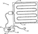
Fig. 1 realizes electric blanket schematic diagram of the present invention;
Fig. 2 is the amplification sectional view of positive temperature coefficient heating element of the present invention;
Fig. 3 is the schematic circuit of safety circuit of the present invention.
Safety device of the present invention can comprise electric blanket, electric pad, and electric notor and building circuit, but be not limited to this various circuit, implement in electric equipment and the power line.In order to illustrate, the situation that the present invention is applied to electric blanket is described below.
Referring to Fig. 1, this figure is depicted as the electric blanket 10 that can use safety device of the present invention.Blanket 10 comprises elongated heating element 12, and it cycles through the passage that forms in the electric blanket cover 14, even distribution heating on the blanket face in known manner back and forth.Though only shown common about 100 feet long heating elements, can contain two or more heating elements in the blanket.Controller 16 connects heating elements 12, and it comprises on/off switch 18, start button 20, and the accent thermal control 22 that makes the heat that user's scalable heating element 12 of blanket 10 produces.Controller 16 is connected to suitable work about electric power power supply by plug 24 with blanket 10.
Fig. 2 is the sectional view of heating element of the present invention 12 used in the electric blanket 10.Heating element 12 uses positive temperature coefficient (PTC) material 26, and this material pushes between a pair of conductor that separates each other 28 and 30 and centers on it, and this material is dog bone (dogbone) shape.Suitable electric insulation coating layer 32 is pressed on the ptc material 26.Though the ad hoc structure of PTC heating element can extensively change, but the preferred embodiment of this heating element is in the U.S. Patent No. 4,277,673 of Kelly, on July 7th, 1981 published, the U.S. Patent No. 4,309 of title " electric conductor self-regulation goods " and Crowley, 596, publish January 5 nineteen eighty-two, open in detail, for referencial use with this two patent here in the title " flexibly from limiting heating cable ".Usually, the ptc material in the heating element has very high sheet resistance, and by polyethylene, and silicon rubber or the analog with mixed carbon black particle constitute, thereby provide specific temperature/resistance characteristic.In a preferred embodiment, each conductor 28 and 30 all has the conductor lines spiral and twines insulating core on it, each core coated with conductive carbon diffusion, and as the U.S. Patent No. 4,309 of Crowley, 596 is described.Be added in coating on each core and offset the high surface resistance of ptc material 26, the result combines for low-resistance electric between ptc material 26 and each conductor 28 and 30.Be in operation, electric current flows between conductor 28 and 30 and the material 26 by therebetween.Ptc material 26 provides resistive hot zone on the whole length of heating element 12, and though Figure 3 shows that discontinuous resistance arranged side by side, ptc material forms a continuous resistance heater between conductor 28 and 30.
Select the composition of ptc material 26 and the physical size of its extruding, make heat radiation reasonably stability under any given temperature of resistance and every foot length.At low temperatures, every foot heat radiation will be greater than under the normal room temperature.And when overheated or the condition of high temperature, heat radiation will be lower than normal condition.Ptc material 26 produces given heat radiation or line temperature from restriction to each varying environment and insulation system.In this way, with regard to heat radiation, tie up or during by unusual constraint (for example, some thing on the blanket top causes by being placed on), 12 pairs of new environment of heating element react and reduce its heat radiation in this zone, attempt to keep rational stable temperature at part blanket 10.
Contain conducting element 34 (Fig. 2) in the heating element 12 of the present invention, it and the parallel length of conductor 28 by heating element with 30.In a preferred embodiment, element 34 is silk or fiber, and in the gap between ptc material 26 and insulating barrier 32 (exaggerative slightly among Fig. 2).So locate the nearly conductor 28 of fiber 34 hot joinings and 30.But, not resembling conductor 28 and 30, conductive fiber 34 uncoated conductive carbon dissipate.So the high surface resistance of FTC material 26 makes conductive fiber 34 electric insulation in fact, thereby the leakage current that flows through between fiber 34 and conductor 28 and 30 does not almost have.In a preferred embodiment, conductor 28 separates with 30, about 0.040 inch of distance, and conductive fiber 34 and each free of conductors, about 0.031 inch of distance.The composition of fiber 34 is as follows, and this composition is running into and the extreme relevant high temperature of superheat state it, and the self-limiting characteristics by ptc material 26 will disconnect can not compensate the time.There are many kinds of materials and composition to can be used for conducting element 34.Can use any metal, alloy, or electric conducting material, and composition thereof, including, but not limited to:
Stainless steel
Zirconium/copper
Copper and copper alloy
Nickel and nickel alloy
Platinum
Lead and lead alloy
Silver
Nickel/chromium
Gold
Nickel/chromium/iron
Aluminium
Brass
Kirsite
Beryllium/copper
Bronze
Iron
Iron/chromium/aluminium
Cadmium alloy
Tin and ashbury metal
Carbon
Phosphorus/bronze
Equally, any metal or conduction coated fiber or line can be used for conductive fiber 34, including, but not limited to:
Apply the line of silver
The line of nickel coating
Apply the line of graphite
The line of coated copper
The line of coated copper/silver
Apply the line of silver/nickel
Apply the line of graphite/iron oxide
The line of carbon coating
And any line with metal mixture or conductive fiber can be used for conductive fiber 34, including, but not limited to:
Fill the plastic cord of silver
Fill the plastic cord of nickel
Fill the plastic cord of carbon
Fill the plastic cord of graphite
Fill the plastic cord of copper/silver
Fill the plastic cord of silver/nickel
The plastic cord of filling aluminum
Fill the plastic cord of copper
Fill the plastic cord of gold
Polytype optical fiber also can be used for conductive fiber 34.
Test above-mentioned different materials and composition, constitute the preferred embodiment of conductive fiber 34 so which kind of to be determined.The test stainless steel fibre, the stainless steel fibre of winding polyester line applies silver-colored polyester line, applies the formal wire of silver, and the polypropylene line of coating silver.Though all tested materials and composition are all functional, determine that the stainless steel fibre of winding polyester line is an optimal material.This particular type optimal material of actual test is made of four strands of 35 microns stainless steel fibres that twine two strand of 150 Denier (equaling about 0.006 inch diameter) polyester line, it can obtain from Bekaert Fibre Technology, as VN35/4 polyester stainless steel wire.The common fusing point of contained polyester is 256 ℃ in this preferred material, and the stainless steel fusing point is generally about 1500 ℃.
In other material of testing for conductive fiber 34, determine that second optimal material is stainless steel fibre (a no polyester line).This particular type second preferred material of actual test is made of 90 strands of 14 microns stainless steel fibres (fusing point is about 1500 ℃ usually), and it can obtain from Bekaert Fibre Technology, as Bekinox #VN 14/1X90/90Z.
For conductive fiber 34 preferred above-mentioned two kinds of optimal components are because the normal bending that its intensity is enough to bear electric blanket is put in order and washing, and enough flexible, can not make electric blanket too stiff.And because the following reason that more hashes out, stainless stranded enough few, heat disconnects conductive fiber 34 before the burning of blanket fabric.Polyester in the most preferred embodiment is of value to the intensity that increases the stainless steel fibre thigh, is beneficial to make handle.
Referring to Fig. 3, this figure is the schematic circuit of safety circuit 37 of the present invention, and its major part is contained in the controller 16 (Fig. 1).Plug 24 is connected to suitable work about electric power power supply with safety circuit, and this power supply is generally ac line voltage.Fuse 38 and power line 40 polyphones, and be used for interrupt circuit when the electric current of flowing through surpasses predetermined value.In a preferred embodiment, fuse 38 is specified 5 amperes, if this explanation electric current is at least 4.5 amperes (its rated values 90%), then fuse is with open circuit.The rated value of fuse 38 is enough high, thereby first to blanket 10 power supplies the time, instantaneous experience is about 4 amperes normal high switching current usually, and fuse 38 does not blow.This high switching current is that ptc material causes, during cooling, this material has extremely low resistance, and this resistance raises fast with the power supply of heating element 12.But if short circuit occurs in the heating element 12, fuse 38 will blow and open circuit fast, and will be as described below.
What connect with fuse 38 is on/off switch 18, and it is by user's control (Fig. 1) of blanket 10.Switch 18 when " on " position closure to connect all the other safety circuits and work about electric power power supply.Safety circuit comprises the relay that is made of relay coil 42 and normal relay switch 44.In a preferred embodiment, relay has 115 volts of alternating voltage coils and single-pole switch, and is made by CornellDubilier Corporation (company).The start button 20 that links to each other with relay coil 42 clicks when making on/off switch 18 closures (" on ") the user moment, makes to form complete loop, and relay coil 42 is energized and has enough electric currents of flowing through and makes relay switch 44 closures thus.After discharging start button 20, though when pressing start button 20, the complete loops (the following describes) that conductive fiber 34 forms will make relay coil 42 fully be encouraged so that latching relay switch 44 closures subsequently through the induced current of relay coil 42.In a preferred embodiment, start button 20 is normally to disconnect instant shut-in by the single pole single throw that Grayhill company makes.
Safety circuit comprises flue 46, its excitation when relay switch 44 and on/off switch 18 closures.Flue 46 is luminous when so encouraging, and as display light representation electric blanket in use.With flue 46 polyphone be current-limiting resistance R1.In a preferred embodiment, flue 46 is neon lamps, and resistance R 1 is 62 kilo-ohms of resistance, and manage 46 and resistance R 1 be combined as specified 120 volts.
Also comprise bimetallic thermal switch 48 in the safety circuit.Connect resistance R 2, it is just encouraged and generation heat when heating element 12 generations are hot, and resistance R 2 is 62 kilo-ohms of carbon resistors in a preferred embodiment.In mode known to a person of ordinary skill in the art, thermal switch 48 is as work the heat decision that this temperature is sent by resistance R 2 with the switch of its temperature correlation.Particularly, when its temperature thermal switch 48 " closure " when a certain critical value is following, and when surpassing critical temperature " disconnection ".By accent thermal control 22 (Fig. 1) the Control Critical temperature of controller 16, and the sensitivity of corresponding thermal switch 48.When surpassing critical temperature and thermal switch 48 disconnections, resistance R 2 and heating element 12 all do not encourage, and make it stop to generate heat and beginning to cool down.When the temperature that is cooled to thermal switch 48 when resistance R 2 dropped to the point of subcritical temperature, thermal switch 48 closures encouraged resistance R 2 and heating element 12 once more.This periodic performance makes the user of blanket 10 utilize accent thermal control 22 can effectively control the heat that heating element 12 produces.
Fig. 3 has also shown heating element 12.When on/off switch 18, when relay switch 44 and bimetallic thermal switch 48 were closed, heating element 12 was energized and by flowing through between conductor 28 and 30 and the electric current of the resistive ptc material 26 of flowing through produces heat.Owing to following reason, the two ends 50 and 52 of conductor 28 link together, and the two ends 54 and 56 of conductor 30 link together.As mentioned above, heating element 12 comprises conducting element or fiber 34, and as shown in Figure 3, it links to each other with working power and extends to a little 60 and length by heating element 12 from putting 58.Is connected relay coil 42 with the conductive fibers 34 of 30 insulation with ptc material 26 and conductor 28 and the unbroken loop flow path of formation conduction current when on/off switch 18 is closed.As mentioned above, this current excitation relay coil 42, thereby latching relay switch 44 closures.
Usually to use aforesaid electric blanket with the closely similar mode of non-electric blanket.Particularly, during use, between the use or when washing, alternating bending and folding electric blanket usually.From these requirements to electric blanket, heating element contained in this electric blanket must be made by suitable size and material, makes it can alternating bending and do not rupture or other problem occurs.Although carefully design and make this heating element,, may damage heating element if blanket produces serious superheat state when connecting working power.This serious superheat state incendivity heating element also brings danger.This damage example to heating element is included in appearance fracture or fault in the contained one or more conductors of heating element, or produces short circuit between conductor.Serious superheat state is normally caused by the electric arc that can reach several thousand degrees centigrade.
Above-mentioned safety circuit of the present invention prevents or eliminates this class problem.In conductor 28 or 30, occur under the situation of single fracture, because it is the two ends of each conductor link together and be connected to working power,, also quite little even the pressure drop that the breakpoint two ends produce has.The accurate amplitude of this pressure drop depends on the fracture position of relative conductor end.Do not have pressure drop on the breakpoint when rupturing in the middle of conductor 28 or 30, and the fracture at conductor one end place produces maximum pressure drop, it equals the overall presure drop on the conductor length.The internal resistance of conductor is depended in pressure drop on the conductor, and it keeps enough low, even make that fracture place can not produce electric arc yet under the situation of maximum pressure drop.In the above described manner, the U.S. Patent No. 2,168,580 of Crowley has more detailed description in the title " electric blanket or pad ", and is for referencial use at this, and safety circuit prevents that the single fracture in one or two of conductor 28 and 30 from producing superheat state.
But when two breakpoints occurring in conductor 28 or 30, the pressure drop on one or two breakpoint is very high usually, thereby produces electric arc.As mentioned above, this electric arc can produce too much heat, if working power is not interrupted, this overheated meeting causes danger, burning ptc material 26, insulating barrier 32, the fiber of final combustion blanket 10.
The conductive fiber 34 of safety circuit of the present invention prevents the dangerous situation development when two breakpoints occurring in conductor 28 or 30.As mentioned above, fiber 34 physical locations are near conductor 28 and 30, and have essentially identical hot state, and the material of its disconnection are formed when running into high temperature.Like this, produce blanket 10 normal work period of expectation heats at heating element 12, electric conducting material 34 does not disconnect, if but develop into the extreme superheat state that causes as electric arc then electric conducting material 34 will disconnect fast.Disconnection in the electric conducting material 34 will be opened the current path of normal guiding electric current by relay coil 42.Make relay coil 42 de-energisations so disconnect, relay switch 44 disconnects and interrupts the working power of heating element 12.As mentioned above, the material of selecting to be used for conductive fiber 34 disconnected fiber 34 before developing into precarious position, and the interruption of work power supply.
When being short-circuited between conductor 28 and 30, the electric current by safety circuit will increase.If short circuit is serious, and working power is not interrupted, and the electric current of increase by conductor 28 and 30 can cause that heating element 12 is overheated, even electric arc occurs, develops into dangerous situation.Surpass predetermined value if flow through the electric current of the fuse 38 of safety circuit, it is by open circuit, thereby the interruption of work power supply prevents this superheat state, and in a preferred embodiment, this predetermined value is about 5.0 amperes.But under the very little situation of the malfunctioning by chance possibility of fuse 38, conductive fiber 34 will prevent the precarious position development.In the above described manner, if because the temperature of short circuit heating element 12 when reaching dangerous high value, fiber 34 will disconnect, thus the interruption of work power supply.
From foregoing description as seen, conductive fiber 34 and safety circuit of the present invention almost can both easily realize preventing superheat state under any condition.And, at various circuit, in electric equipment and the electric wire,, can both realize the advantage of this safety circuit no matter power supply is to exchange or direct current.
Above-mentioned just preferred embodiment.Those skilled in the art and utilize people of the present invention will revise the present invention.So, should understand shown in the accompanying drawing and embodiment described above is in order to illustrate rather than limit protection scope of the present invention that protection scope of the present invention is determined by the following claim of illustrating by the Patent Law principle.
Claims (12)
1. an electrical safety circuit is used to have the electric equipment by the circuit element of working power excitation, and this safety circuit comprises:
Conducting element, nearly at least one circuit element by the working power excitation of its hot joining constitutes described conducting element to disconnect in response to high temperature; And
The switching circuit that connects described conducting element and working power, described switching circuit interrupts the working power of electric equipment in response to the disconnection of described conducting element.
2. safety circuit as claimed in claim 1 is characterized in that described conducting element comprises the stainless steel fibre that twines the polyester line.
3. safety circuit as claimed in claim 1 is characterized in that described conducting element comprises stainless steel fibre.
4. safety circuit as claimed in claim 1 is characterized in that described switching circuit comprises relay.
5. safety circuit as claimed in claim 1 also comprises the fuse that connects working power, and described fuse interrupts the working power of electric equipment when surpassing predetermined current value.
6. safety circuit as claimed in claim 1 is characterized in that electric equipment is an electric blanket.
7. safety circuit as claimed in claim 6, wherein at least one circuit element is the positive temperature coefficient heating element with two conductors that are separated from each other, and wherein said conducting element is included in the heating element and with the conductor parallel running.
8. safety circuit as claimed in claim 7, each that it is characterized in that two conductors that are separated from each other has the two ends that connect together.
9. safety circuit as claimed in claim 1 is characterized in that the preceding disconnection of catching fire of described conducting element in electric equipment.
10. safety circuit as claimed in claim 1 is characterized in that described conducting element disconnects if when occurring open circuit or short circuit in the electric equipment.
11. an electrical safety circuit is used to have the electric equipment by the circuit element of working power excitation, this safety circuit comprises:
The device of guiding electric current, nearly at least one circuit element by the working power excitation of the hot joining of described electric installation constitutes described electric installation to disconnect in response to the unusual high temperature of at least one circuit element; And
The switching device that connects described electric installation and working power, described switching device turn-offs the working power of electric equipment in response to the disconnection of described electric installation.
12. a method of protecting electric equipment, this electric equipment is by the working power excitation and wherein have superheat state, and this method comprises:
Disconnect the conducting element of the nearly superheat state of hot joining; And
Turn-off the power supply of electric equipment in response to the disconnection of described conducting element.
Applications Claiming Priority (2)
| Application Number | Priority Date | Filing Date | Title |
|---|---|---|---|
| US08/652,898 US5801914A (en) | 1996-05-23 | 1996-05-23 | Electrical safety circuit with a breakable conductive element |
| US08/652,898 | 1996-05-23 |
Publications (2)
| Publication Number | Publication Date |
|---|---|
| CN1170261A CN1170261A (en) | 1998-01-14 |
| CN1061790C true CN1061790C (en) | 2001-02-07 |
Family
ID=24618657
Family Applications (1)
| Application Number | Title | Priority Date | Filing Date |
|---|---|---|---|
| CN97114836A Expired - Fee Related CN1061790C (en) | 1996-05-23 | 1997-05-23 | Safety circuit for electrical devices |
Country Status (9)
| Country | Link |
|---|---|
| US (1) | US5801914A (en) |
| EP (1) | EP0809417A3 (en) |
| JP (1) | JP3023332B2 (en) |
| KR (1) | KR970078742A (en) |
| CN (1) | CN1061790C (en) |
| AR (1) | AR003660A1 (en) |
| AU (1) | AU2357597A (en) |
| CA (1) | CA2205819A1 (en) |
| MX (1) | MX9703836A (en) |
Families Citing this family (40)
| Publication number | Priority date | Publication date | Assignee | Title |
|---|---|---|---|---|
| TW371379B (en) * | 1997-01-09 | 1999-10-01 | Daifuku Kk | Protective device of non-contact feeder system |
| US5900999A (en) * | 1997-01-09 | 1999-05-04 | Donnelly Corporation | Housing with integral electrical connectors for a rearview mirror actuator assembly |
| US6229123B1 (en) | 1998-09-25 | 2001-05-08 | Thermosoft International Corporation | Soft electrical textile heater and method of assembly |
| DE19827374C2 (en) * | 1998-06-19 | 2001-05-23 | Daimler Chrysler Ag | Fuse element for electrical systems |
| US6452138B1 (en) * | 1998-09-25 | 2002-09-17 | Thermosoft International Corporation | Multi-conductor soft heating element |
| AU756477C (en) * | 1998-12-23 | 2003-09-11 | Fisher & Paykel Healthcare Limited | Fault protection system for a respiratory conduit heater element |
| US7202444B2 (en) * | 1999-01-25 | 2007-04-10 | Illinois Tool Works Inc. | Flexible seat heater |
| US6884965B2 (en) * | 1999-01-25 | 2005-04-26 | Illinois Tool Works Inc. | Flexible heater device |
| US7053344B1 (en) | 2000-01-24 | 2006-05-30 | Illinois Tool Works Inc | Self regulating flexible heater |
| US6713733B2 (en) | 1999-05-11 | 2004-03-30 | Thermosoft International Corporation | Textile heater with continuous temperature sensing and hot spot detection |
| US6403935B2 (en) * | 1999-05-11 | 2002-06-11 | Thermosoft International Corporation | Soft heating element and method of its electrical termination |
| US6563094B2 (en) | 1999-05-11 | 2003-05-13 | Thermosoft International Corporation | Soft electrical heater with continuous temperature sensing |
| US6492629B1 (en) | 1999-05-14 | 2002-12-10 | Umesh Sopory | Electrical heating devices and resettable fuses |
| WO2003011000A1 (en) * | 2001-07-05 | 2003-02-06 | King's Metal Fiber Technologies Co., Ltd. | Heating apparatus having heating line combined with soft matrix |
| US6770854B1 (en) * | 2001-08-29 | 2004-08-03 | Inotec Incorporated | Electric blanket and system and method for making an electric blanket |
| GB0216932D0 (en) * | 2002-07-20 | 2002-08-28 | Heat Trace Ltd | Electrical heating cable |
| DE10234389A1 (en) * | 2002-07-23 | 2004-02-05 | Alcoa Fujikura Gesellschaft mit beschränkter Haftung | Line arrangement for vehicle electrical systems |
| US6713724B1 (en) | 2002-10-11 | 2004-03-30 | Perfect Fit Industries, Inc. | Heating element arrangement for an electric blanket or the like |
| US20040070904A1 (en) * | 2002-10-11 | 2004-04-15 | Carr Sheldon P. | Over-voltage protection arrangement for a low voltage power supply |
| US6888108B2 (en) | 2002-10-11 | 2005-05-03 | Perfect Fit Industries, Inc. | Low voltage power supply system for an electric blanket or the like |
| US7306283B2 (en) | 2002-11-21 | 2007-12-11 | W.E.T. Automotive Systems Ag | Heater for an automotive vehicle and method of forming same |
| KR20060023572A (en) * | 2003-06-24 | 2006-03-14 | 코닌클리케 필립스 일렉트로닉스 엔.브이. | Stretchable fabric switch |
| GB0322047D0 (en) * | 2003-09-20 | 2003-10-22 | Heat Trace Ltd | Method of processing parallel resistance electrical heating cable |
| US6958463B1 (en) | 2004-04-23 | 2005-10-25 | Thermosoft International Corporation | Heater with simultaneous hot spot and mechanical intrusion protection |
| US7889733B2 (en) | 2004-04-28 | 2011-02-15 | Cisco Technology, Inc. | Intelligent adjunct network device |
| FI120926B (en) * | 2008-01-25 | 2010-04-30 | Abb Oy | The load control apparatus |
| US20100314381A1 (en) * | 2008-01-28 | 2010-12-16 | Ching Chuan Wang | Heating device |
| US8544942B2 (en) | 2010-05-27 | 2013-10-01 | W.E.T. Automotive Systems, Ltd. | Heater for an automotive vehicle and method of forming same |
| DE102011114949A1 (en) | 2010-10-19 | 2012-04-19 | W.E.T. Automotive Systems Ag | Electrical conductor |
| DE102012000977A1 (en) | 2011-04-06 | 2012-10-11 | W.E.T. Automotive Systems Ag | Heating device for complex shaped surfaces |
| DE102011121979A1 (en) | 2011-09-14 | 2012-11-22 | W.E.T. Automotive Systems Ag | Tempering equipment for use in handle piece of shifting knob of gear shift of vehicle for keeping hand of user at moderate temperature, has heating device provided with heating resistor, and strand inserted into recesses of carrier |
| US10201039B2 (en) | 2012-01-20 | 2019-02-05 | Gentherm Gmbh | Felt heater and method of making |
| DE102013006410A1 (en) | 2012-06-18 | 2013-12-19 | W.E.T. Automotive Systems Ag | Sheet installed in function region, used as floor mat for e.g. motor car, has heating device including electrodes which are arranged spaced apart from electrical resistor, and sensor for detecting temperature of environment |
| US10772510B2 (en) * | 2012-08-22 | 2020-09-15 | Midmark Corporation | Vital signs monitor for controlling power-adjustable examination table |
| DE102012017047A1 (en) | 2012-08-29 | 2014-03-06 | W.E.T. Automotive Systems Ag | Electric heater |
| DE102012024903A1 (en) | 2012-12-20 | 2014-06-26 | W.E.T. Automotive Systems Ag | Flat structure with electrical functional elements |
| GB2514385A (en) * | 2013-05-22 | 2014-11-26 | Heat Trace Ltd | Heating cable |
| EP3468300B1 (en) * | 2017-08-11 | 2020-09-16 | SH Tech Co., Ltd. | Heating unit and heating module comprising same |
| CN107898273A (en) * | 2017-12-18 | 2018-04-13 | 无锡优耐特能源科技有限公司 | A kind of security protection foot pad and safety relay device |
| US11526184B2 (en) | 2018-04-10 | 2022-12-13 | Lear Corporation | Vehicle seat including a heating mat having overheating prevention and protection |
Citations (2)
| Publication number | Priority date | Publication date | Assignee | Title |
|---|---|---|---|---|
| CN2096180U (en) * | 1991-07-04 | 1992-02-12 | 张福来 | Safety protector for electric blanket |
| CN2133110Y (en) * | 1992-07-14 | 1993-05-12 | 大连电热毯厂 | Interruption protect temp. control switch for heating blanket |
Family Cites Families (37)
| Publication number | Priority date | Publication date | Assignee | Title |
|---|---|---|---|---|
| US3114825A (en) * | 1961-01-30 | 1963-12-17 | Gen Electric | Electric heating pad |
| NL288627A (en) * | 1962-02-21 | |||
| US3215896A (en) * | 1962-10-04 | 1965-11-02 | Gen Electric | Fast response overload protection circuit |
| US3325718A (en) * | 1963-12-04 | 1967-06-13 | Gen Lab Associates Inc | Protective circuit for vibrator type d.c.-a.c. converters |
| US3493815A (en) * | 1967-07-19 | 1970-02-03 | Gen Electric | Electric protective system |
| US3600634A (en) * | 1969-12-16 | 1971-08-17 | Integrated Systems Inc | Protective control circuit against transient voltages |
| US3628093A (en) * | 1970-04-13 | 1971-12-14 | Northern Electric Co | Thermostat overheat protection system for an electric appliance such as a blanket |
| USRE28656E (en) * | 1971-10-26 | 1975-12-16 | Thermostatless blanket control circuit | |
| US3845355A (en) * | 1973-05-04 | 1974-10-29 | Borg Warner | Fault protection circuit for an adjustable motorized hospital bed |
| US3878434A (en) * | 1973-12-10 | 1975-04-15 | Leeds & Northrup Co | Power-limiting electrical barrier device |
| US3968407A (en) * | 1974-03-27 | 1976-07-06 | Petrolite Corporation | Redundant intrinsic safety barrier |
| FR2315752A1 (en) * | 1975-06-24 | 1977-01-21 | Babled Frederic | Thermal overload protection for LV cable - has fuse wire installed inside cable which is monitored for continuity |
| US4034185A (en) * | 1975-09-02 | 1977-07-05 | Northern Electric Company | Electric blanket control circuit |
| GB1599709A (en) * | 1978-01-31 | 1981-10-07 | Dreamland Electrical Appliance | Heating circuits |
| US4277673A (en) * | 1979-03-26 | 1981-07-07 | E-B Industries, Inc. | Electrically conductive self-regulating article |
| US4450496A (en) * | 1979-08-16 | 1984-05-22 | Raychem Corporation | Protection of certain electrical systems by use of PTC device |
| CA1156300A (en) * | 1980-04-01 | 1983-11-01 | Gordon S. Carlson | Electric blanket safety circuit |
| US4309597A (en) * | 1980-05-19 | 1982-01-05 | Sunbeam Corporation | Blanket wire utilizing positive temperature coefficient resistance heater |
| US4271350A (en) * | 1980-05-19 | 1981-06-02 | Sunbeam Corporation | Blanket wire utilizing positive temperature coefficient resistance heater |
| US4309596A (en) * | 1980-06-24 | 1982-01-05 | Sunbeam Corporation | Flexible self-limiting heating cable |
| US4436986A (en) * | 1981-11-23 | 1984-03-13 | Sunbeam Corporation | Electric blanket safety circuit |
| US4439801A (en) * | 1982-04-12 | 1984-03-27 | Xenell Corporation | Electrical load imbalance detection and protection apparatus |
| CA1235450A (en) * | 1983-05-11 | 1988-04-19 | Kazunori Ishii | Flexible heating cable |
| US4577094A (en) * | 1983-10-05 | 1986-03-18 | Fieldcrest Mills, Inc. | Electrical heating apparatus protected against an overheating condition |
| US4550358A (en) * | 1984-02-13 | 1985-10-29 | Sunbeam Corporation | Protective circuit for portable electric appliances |
| US4547658A (en) * | 1984-06-13 | 1985-10-15 | Sunbeam Corporation | Multiple heat fusing wire circuit for underblankets |
| CA1244863A (en) * | 1984-12-06 | 1988-11-15 | George C. Crowley | Electric blanket or pad having improved positive temperature coefficient heater circuit |
| JPS62100968A (en) * | 1985-10-29 | 1987-05-11 | 東レ株式会社 | String heater element and manufacture of the same |
| US5143649A (en) * | 1985-12-06 | 1992-09-01 | Sunbeam Corporation | PTC compositions containing low molecular weight polymer molecules for reduced annealing |
| US4822983A (en) * | 1986-12-05 | 1989-04-18 | Raychem Corporation | Electrical heaters |
| US5081339A (en) * | 1990-06-01 | 1992-01-14 | Sunbeam Corporation | Water bed heater |
| US5451747A (en) * | 1992-03-03 | 1995-09-19 | Sunbeam Corporation | Flexible self-regulating heating pad combination and associated method |
| GB9208182D0 (en) * | 1992-04-11 | 1992-05-27 | Cole Graham M | Improvements in or relating to electrically heated panels |
| US5369247A (en) * | 1992-10-29 | 1994-11-29 | Doljack; Frank A. | Self-regulating electrical heater system and method |
| US5420397A (en) * | 1992-12-15 | 1995-05-30 | Micro Weiss Electronics, Inc. | Control device and safety circuit for heating pads with PTC heater |
| US5424895A (en) * | 1993-08-17 | 1995-06-13 | Gaston; William R. | Electrical wiring system with overtemperature protection |
| US5412181A (en) * | 1993-12-27 | 1995-05-02 | The B. F. Goodrich Company | Variable power density heating using stranded resistance wire |
-
1996
- 1996-05-23 US US08/652,898 patent/US5801914A/en not_active Expired - Fee Related
-
1997
- 1997-05-22 CA CA002205819A patent/CA2205819A1/en not_active Abandoned
- 1997-05-22 AU AU23575/97A patent/AU2357597A/en not_active Abandoned
- 1997-05-23 JP JP9169374A patent/JP3023332B2/en not_active Expired - Lifetime
- 1997-05-23 CN CN97114836A patent/CN1061790C/en not_active Expired - Fee Related
- 1997-05-23 EP EP97303563A patent/EP0809417A3/en not_active Withdrawn
- 1997-05-23 MX MX9703836A patent/MX9703836A/en unknown
- 1997-05-23 AR ARP970102193A patent/AR003660A1/en unknown
- 1997-05-23 KR KR1019970020111A patent/KR970078742A/en not_active Application Discontinuation
Patent Citations (2)
| Publication number | Priority date | Publication date | Assignee | Title |
|---|---|---|---|---|
| CN2096180U (en) * | 1991-07-04 | 1992-02-12 | 张福来 | Safety protector for electric blanket |
| CN2133110Y (en) * | 1992-07-14 | 1993-05-12 | 大连电热毯厂 | Interruption protect temp. control switch for heating blanket |
Also Published As
| Publication number | Publication date |
|---|---|
| JPH10144192A (en) | 1998-05-29 |
| EP0809417A3 (en) | 1998-02-04 |
| MX9703836A (en) | 1998-04-30 |
| CA2205819A1 (en) | 1997-11-23 |
| CN1170261A (en) | 1998-01-14 |
| AU2357597A (en) | 1997-11-27 |
| US5801914A (en) | 1998-09-01 |
| KR970078742A (en) | 1997-12-12 |
| AR003660A1 (en) | 1998-09-09 |
| EP0809417A2 (en) | 1997-11-26 |
| JP3023332B2 (en) | 2000-03-21 |
Similar Documents
| Publication | Publication Date | Title |
|---|---|---|
| CN1061790C (en) | Safety circuit for electrical devices | |
| MXPA97003836A (en) | Electric device security circuit | |
| EP0125913B1 (en) | Flexible heating wire | |
| CA1268510A (en) | Electrical heaters | |
| AU663171B2 (en) | Improvements in or relating to electrically heated panels | |
| AU607666B2 (en) | Flexible, elongated positive temperature coefficient heating assembly and method | |
| NZ202222A (en) | Electric blanket gas tube safety heating circuit | |
| KR20110031982A (en) | Heater wire control circuit and method to operate a heating element | |
| US4684785A (en) | Electric blankets | |
| US4278874A (en) | Heating circuits | |
| US4491723A (en) | Heating circuit with overheat safety control feature | |
| CN1823552B (en) | Heating blanket | |
| EP0562850A2 (en) | Heating device | |
| WO2006072765A1 (en) | A controller for a heating cable | |
| NZ196568A (en) | Electric blanket:automatic disconnection with element open circuit | |
| CA1244863A (en) | Electric blanket or pad having improved positive temperature coefficient heater circuit | |
| CA2492216A1 (en) | Electrical heating cable | |
| GB2028608A (en) | Heating circuits | |
| GB2236236A (en) | Electric heating cable | |
| EP0668646B1 (en) | Improvements in or relating to electrically heated panels | |
| CN2169264Y (en) | Safety heater for electric heating pad | |
| EP0577378A1 (en) | Electric heating cable | |
| GB2268643A (en) | Electric heating cable. | |
| KR950004454Y1 (en) | Protective apparatus | |
| GB2154816A (en) | Electrical heating circuits |
Legal Events
| Date | Code | Title | Description |
|---|---|---|---|
| C06 | Publication | ||
| PB01 | Publication | ||
| C14 | Grant of patent or utility model | ||
| GR01 | Patent grant | ||
| C19 | Lapse of patent right due to non-payment of the annual fee | ||
| CF01 | Termination of patent right due to non-payment of annual fee |