CN106170090B - Method for encoding/decoding picture block - Google Patents
Method for encoding/decoding picture block Download PDFInfo
- Publication number
- CN106170090B CN106170090B CN201610325693.0A CN201610325693A CN106170090B CN 106170090 B CN106170090 B CN 106170090B CN 201610325693 A CN201610325693 A CN 201610325693A CN 106170090 B CN106170090 B CN 106170090B
- Authority
- CN
- China
- Prior art keywords
- luminance
- block
- average value
- representation
- picture
- Prior art date
- Legal status (The legal status is an assumption and is not a legal conclusion. Google has not performed a legal analysis and makes no representation as to the accuracy of the status listed.)
- Active
Links
Images


Classifications
-
- H—ELECTRICITY
- H04—ELECTRIC COMMUNICATION TECHNIQUE
- H04N—PICTORIAL COMMUNICATION, e.g. TELEVISION
- H04N19/00—Methods or arrangements for coding, decoding, compressing or decompressing digital video signals
- H04N19/10—Methods or arrangements for coding, decoding, compressing or decompressing digital video signals using adaptive coding
- H04N19/169—Methods or arrangements for coding, decoding, compressing or decompressing digital video signals using adaptive coding characterised by the coding unit, i.e. the structural portion or semantic portion of the video signal being the object or the subject of the adaptive coding
- H04N19/17—Methods or arrangements for coding, decoding, compressing or decompressing digital video signals using adaptive coding characterised by the coding unit, i.e. the structural portion or semantic portion of the video signal being the object or the subject of the adaptive coding the unit being an image region, e.g. an object
- H04N19/176—Methods or arrangements for coding, decoding, compressing or decompressing digital video signals using adaptive coding characterised by the coding unit, i.e. the structural portion or semantic portion of the video signal being the object or the subject of the adaptive coding the unit being an image region, e.g. an object the region being a block, e.g. a macroblock
-
- H—ELECTRICITY
- H04—ELECTRIC COMMUNICATION TECHNIQUE
- H04N—PICTORIAL COMMUNICATION, e.g. TELEVISION
- H04N19/00—Methods or arrangements for coding, decoding, compressing or decompressing digital video signals
- H04N19/10—Methods or arrangements for coding, decoding, compressing or decompressing digital video signals using adaptive coding
- H04N19/169—Methods or arrangements for coding, decoding, compressing or decompressing digital video signals using adaptive coding characterised by the coding unit, i.e. the structural portion or semantic portion of the video signal being the object or the subject of the adaptive coding
- H04N19/182—Methods or arrangements for coding, decoding, compressing or decompressing digital video signals using adaptive coding characterised by the coding unit, i.e. the structural portion or semantic portion of the video signal being the object or the subject of the adaptive coding the unit being a pixel
-
- H—ELECTRICITY
- H04—ELECTRIC COMMUNICATION TECHNIQUE
- H04N—PICTORIAL COMMUNICATION, e.g. TELEVISION
- H04N19/00—Methods or arrangements for coding, decoding, compressing or decompressing digital video signals
- H04N19/10—Methods or arrangements for coding, decoding, compressing or decompressing digital video signals using adaptive coding
- H04N19/169—Methods or arrangements for coding, decoding, compressing or decompressing digital video signals using adaptive coding characterised by the coding unit, i.e. the structural portion or semantic portion of the video signal being the object or the subject of the adaptive coding
- H04N19/186—Methods or arrangements for coding, decoding, compressing or decompressing digital video signals using adaptive coding characterised by the coding unit, i.e. the structural portion or semantic portion of the video signal being the object or the subject of the adaptive coding the unit being a colour or a chrominance component
-
- H—ELECTRICITY
- H04—ELECTRIC COMMUNICATION TECHNIQUE
- H04N—PICTORIAL COMMUNICATION, e.g. TELEVISION
- H04N19/00—Methods or arrangements for coding, decoding, compressing or decompressing digital video signals
- H04N19/50—Methods or arrangements for coding, decoding, compressing or decompressing digital video signals using predictive coding
-
- H—ELECTRICITY
- H04—ELECTRIC COMMUNICATION TECHNIQUE
- H04N—PICTORIAL COMMUNICATION, e.g. TELEVISION
- H04N19/00—Methods or arrangements for coding, decoding, compressing or decompressing digital video signals
- H04N19/60—Methods or arrangements for coding, decoding, compressing or decompressing digital video signals using transform coding
- H04N19/61—Methods or arrangements for coding, decoding, compressing or decompressing digital video signals using transform coding in combination with predictive coding
-
- H—ELECTRICITY
- H04—ELECTRIC COMMUNICATION TECHNIQUE
- H04N—PICTORIAL COMMUNICATION, e.g. TELEVISION
- H04N9/00—Details of colour television systems
- H04N9/64—Circuits for processing colour signals
- H04N9/65—Circuits for processing colour signals for synchronous modulators
-
- H—ELECTRICITY
- H04—ELECTRIC COMMUNICATION TECHNIQUE
- H04N—PICTORIAL COMMUNICATION, e.g. TELEVISION
- H04N9/00—Details of colour television systems
- H04N9/64—Circuits for processing colour signals
- H04N9/66—Circuits for processing colour signals for synchronous demodulators
-
- H—ELECTRICITY
- H04—ELECTRIC COMMUNICATION TECHNIQUE
- H04N—PICTORIAL COMMUNICATION, e.g. TELEVISION
- H04N9/00—Details of colour television systems
- H04N9/77—Circuits for processing the brightness signal and the chrominance signal relative to each other, e.g. adjusting the phase of the brightness signal relative to the colour signal, correcting differential gain or differential phase
-
- H—ELECTRICITY
- H04—ELECTRIC COMMUNICATION TECHNIQUE
- H04N—PICTORIAL COMMUNICATION, e.g. TELEVISION
- H04N19/00—Methods or arrangements for coding, decoding, compressing or decompressing digital video signals
- H04N19/30—Methods or arrangements for coding, decoding, compressing or decompressing digital video signals using hierarchical techniques, e.g. scalability
- H04N19/34—Scalability techniques involving progressive bit-plane based encoding of the enhancement layer, e.g. fine granular scalability [FGS]
-
- H—ELECTRICITY
- H04—ELECTRIC COMMUNICATION TECHNIQUE
- H04N—PICTORIAL COMMUNICATION, e.g. TELEVISION
- H04N19/00—Methods or arrangements for coding, decoding, compressing or decompressing digital video signals
- H04N19/90—Methods or arrangements for coding, decoding, compressing or decompressing digital video signals using coding techniques not provided for in groups H04N19/10-H04N19/85, e.g. fractals
- H04N19/98—Adaptive-dynamic-range coding [ADRC]
Abstract
The present disclosure relates generally to a method and apparatus for encoding a picture block having a luminance component. The method is characterized in that the method comprises: by subtracting a first representation (L) of the calculated average value of the luminance component from the luminance componentl,LlD) Obtaining (103, 301) a luminance residual block (L)r) (ii) a By applying a transfer function to the mean value (L) of the luminance componentsl) In order to reduce the dynamic range of the mean value, a second representation (f (L) of the mean value is obtained (102)l),f(Ll)D) (ii) a For the pass luminance residual block (L)r) Second representation from the mean (f (L)l),f(Ll)D) Luminance blocks (L) obtained by adding (105, 302) togethere) And (6) coding is carried out. The present disclosure also relates to a method and apparatus for decoding a picture block.
Description
Technical Field
The present disclosure relates generally to picture/video encoding and decoding. In particular, but not exclusively, the technical field of the present disclosure relates to encoding/decoding of pictures whose pixel values belong to a high dynamic range.
Background
This section is intended to introduce the reader to various aspects of art, which may be related to various aspects of the present disclosure that are described and/or claimed below. This discussion is believed to be helpful in providing the reader with background information to facilitate a better understanding of the various aspects of the present disclosure. Accordingly, it should be understood that these statements are to be read in this light, and not as admissions of prior art.
In the following, a picture contains one or several arrays of samples (pixel values) in a specific picture/video format specifying all information related to the pixel values of the picture (or video) and all information that can be used by a display and/or any other device, for example, to visualize and/or decode the picture (or video). A picture comprises at least one component in the shape of a first array of samples, typically a luminance (or luma) component, and possibly at least one other component in the shape of at least one other array of samples, typically a color component. Or, equivalently, the same information may also be represented by a set of arrays of color samples, such as the conventional three primary RGB representation.
The pixel value is represented by a vector of n values, where n is the number of components. Each value of the vector is expressed in a number of bits that defines the maximum dynamic range of the pixel value.
A picture block refers to a group of pixels belonging to the picture, and the pixel value of a block refers to the value of the pixel belonging to the block. A picture block may be a macroblock, a coding unit or a transform unit according to H264 or H265, or any other group of pixels forming an area of a picture of any arbitrary shape (not limited to a square or rectangular shape).
A low dynamic range picture (LDR picture) is a picture whose luminance values are expressed in a limited number of bits, often 8 or 10 bits. This limited representation does not allow a correct rendering of small signal variations, especially in the dark and bright luminance range. In high dynamic range images (HDR images), the signal representation is extended in order to maintain a high accuracy of the signal over its entire range. In HDR images, pixel values are usually expressed in floating-point format (32-bit or 16-bit per component, i.e. floating-point or half-floating), the most popular format being openEXR half-floating-point format (16-bit per RGB component, i.e. 48-bit per pixel) or in integers with long expression (typically at least 16-bit).
A typical method of encoding HDR images is to apply a transfer function to a picture in order to reduce the dynamic range of the picture (typically 8 bits). The transferred pictures are then encoded by means of a conventional coding scheme (JPEG/JPEG2000, JPGE 2000: "Information technology-JPEG 2000image coding system: Code coding system", ITU-T recommendation T.800, month 8 2002; or for video MPEG-2, H.264/AVC: "Advanced video coding for genetic audio services", ITU-T H.264 (9 th edition), month 2 2014; or H265/HEVC, HEVC: "High Efficiency video coding", ITU-T H.265, month 10 2014).
Typical transfer functions are defined in a contribution to the ITU standardization organization entitled "Image dynamic range in hierarchy systems" (document 6C/77-E, day 10/2012).
At the decoder side, the transferred picture is obtained and the inverse transfer function is applied on the decoded transferred picture. The term "inverse transfer function" means that if the transfer function and the inverse transfer function are applied successively to an input picture (without any encoding/decoding), the resulting picture and the input picture are the same picture. Any monotonic function can be a transfer function.
Using such typical encoding schemes for encoding HDR pictures involves the large size of the compressed pictures. Thus, this typical approach cannot be used in applications requiring high coding performance, such as, for example, in the context of transmissions requiring high compression rates.
The present disclosure has been devised in view of the foregoing.
Disclosure of Invention
In view of the foregoing, aspects of the present disclosure are directed to creating and maintaining semantic relationships between data objects on a computer system. The following presents a simplified summary of the disclosure in order to provide a basic understanding of some aspects of the disclosure. This summary is not an extensive overview of the disclosure. It is not intended to identify key or critical elements of the disclosure. The following summary merely presents some aspects of the disclosure in a simplified form as a prelude to the more detailed description provided below.
The present disclosure is directed to remedy at least one of the shortcomings of the prior art with a method of encoding a picture block having a luminance component. The method comprises the following steps:
-obtaining a luminance residual block by subtracting a first representation of the average value of the luminance component from the luminance component;
-by applying a transfer function to the mean value (L) of the luminance componentsl) So as to reduce the dynamic range of the mean value, obtaining a second representation of the mean value;
-encoding a luminance block obtained by adding together the luminance residual block and the second representation of the average value.
In accordance with the present principles, obtaining the second representation of the average further comprises quantizing the transferred average according to a sampling factor, and obtaining the first representation of the average by applying another transfer function to the second representation of the average, the other transfer function being an inverse of the transfer function.
In accordance with the present principles, the method further comprises encoding a residual average value obtained by subtracting an average value of a decoded version of the encoded luma block from the first representation of the average value.
In accordance with the present principles, the picture block further comprises at least one color component, wherein the luminance residual block (L)r) A perceptual space belonging to a metric having a value representing a difference between visual perceptions of two points of said perceptual space, said metric being defined such that there is a perception threshold below which a human being is unable to perceive a visual difference between two colors of the perceptual space; and enables control of visual loss in the displayed decoded version of the picture block to be encoded.
In accordance with the present principles, the present disclosure relates to a method of decoding a picture block having a luminance component expressed in an original number of bits. The method comprises the following steps:
-obtaining a luminance residual block by subtracting an average of said luminance block from a luminance block;
-obtaining a decoded luminance component of the picture block by adding together the luminance residual block and a representation of the mean value of the luminance block expressed in the original number of bits.
In accordance with the present principles, a representation of the average of a luminance block is obtained by adding together the residual average and the average of the luminance block.
According to the present principles, the picture block comprises at least one color component, wherein the method further comprises applying an inverse transformation to a luminance residual block belonging to a perceptual space having a measure representing a difference between visual perceptions of two points of said perceptual space, said measure being defined such that there is a perception threshold below which a human being is unable to perceive a visual difference between two colors of the perceptual space and such that a visual loss in the displayed decoded version of the picture block can be controlled.
According to another of its aspects, the present disclosure relates to a signal carrying a coded luminance block, characterized in that it also carries information data indicating the sum of a luminance component of the coded luminance block representation picture block and a representation of an average of said luminance component.
According to its other aspects, the present disclosure relates to: a device comprising a processor configured to implement the above-described method; a computer program product comprising program code instructions for carrying out the steps of the above-mentioned method when the program is executed on a computer; a processor readable medium having stored therein instructions for causing a processor to perform at least the steps of the above-described method; and a non-transitory storage medium carrying instructions of program code which, when the program is executed on a computer, perform the steps of the above-described method.
The particular features of the present disclosure, as well as other objects, advantages, features, and uses of the disclosure, will become apparent from the following description of the embodiments, which is to be read in connection with the accompanying drawings.
Drawings
Embodiments of the present disclosure are illustrated in the accompanying drawings. Wherein:
fig. 1 shows a block diagram of the steps of a method for encoding a picture block according to an embodiment of the present disclosure;
fig. 2 shows a block diagram of the steps of a method for decoding a picture block according to an example of the present principles;
fig. 3 shows a block diagram of the steps of a method for encoding a picture block according to an example of the present principles.
Fig. 4 shows a block diagram of the steps of a method for decoding a picture block according to an example of the present principles.
Figure 5 shows a block diagram of the steps of a variant of the method of figure 3;
figure 6 shows a block diagram of the steps of a variant of the method of figure 4;
figure 7 shows a block diagram of the steps of a variant of the method of figure 1;
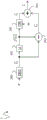
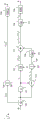
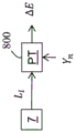
figures 8a, 8b show diagrams of steps of a method of determining an upper limit according to an example of the present principles;
figure 9 shows a block diagram of the steps of a variant of the method of figure 2;
figure 10 shows a block diagram of the steps of a variant of the method of figure 3;
figure 11 shows a block diagram of the steps of a variant of the method of figure 4;
figure 12 shows a block diagram of the steps of a variant of the method of figure 5;
figure 13 shows a block diagram of the steps of a variant of the method of figure 6;
figure 14 shows an example of an architecture of a device according to an example of the present principles;
figure 15 shows two remote devices communicating over a communication network, in accordance with an example of the present principles; and
fig. 16 shows the syntax of an exemplary signal according to the present principles.
The same reference numbers are used to identify similar or identical elements.
Detailed Description
The present disclosure now will be described more fully hereinafter with reference to the accompanying drawings, in which embodiments of the disclosure are shown. This disclosure may, however, be embodied in many alternate forms and should not be construed as limited to the embodiments set forth herein. Accordingly, while the disclosure is susceptible to various modifications and alternative forms, specific embodiments thereof have been shown by way of example in the drawings and will herein be described in detail. It should be understood, however, that there is no intention to limit the disclosure to the specific forms disclosed; on the contrary, the intention is to cover all modifications, equivalents, and alternatives falling within the spirit and scope of the disclosure as defined by the appended claims.
The terminology used herein is for the purpose of describing particular embodiments only and is not intended to be limiting of the disclosure. As used herein, the singular forms "a", "an" and "the" are intended to include the plural forms as well, unless the context clearly indicates otherwise. It will be further understood that the terms "comprises," "comprising," "includes" and/or "including," when used in this specification, specify the presence of stated features, integers, steps, operations, elements, and/or components, but do not preclude the presence or addition of one or more other features, integers, steps, operations, elements, components, and/or groups thereof. Also, when an element is referred to as being "responsive" or "connected" to another element, it can be directly responsive or connected to the other element or intervening elements may be present. In contrast, when an element is referred to as being "directly responsive" or "directly connected" to another element, there are no intervening elements present. As used herein, the term "and/or" includes any and all combinations of one or more of the associated listed items and may be abbreviated as "/".
It will be understood that, although the terms first, second, etc. may be used herein to describe various elements, these elements should not be limited by these terms. These terms are only used to distinguish one element from another. For example, a first element could be termed a second element, and, similarly, a second element could be termed a first element, without departing from the teachings of the present disclosure.
Although some of the figures include arrows on communication paths to show the primary direction of communication, it is to be understood that communication may occur in the opposite direction to the depicted arrows.
Some embodiments are described with reference to block diagrams and operational flow diagrams, wherein each block represents a circuit element, module, or portion of code, which comprises one or more executable instructions for implementing the specified logical function(s). It should also be noted that, in other implementations, the functions noted in the blocks may occur out of the order noted. For example, two blocks shown in succession may, in fact, be executed substantially concurrently, or the blocks may sometimes be executed in the reverse order, depending upon the functionality involved.
Reference herein to "one embodiment" or "an embodiment" means that a particular feature, structure, or characteristic described in connection with the embodiment can be included in at least one implementation of the disclosure. The appearances of the phrases "in one embodiment" or "according to an embodiment" in various places in the specification are not necessarily all referring to the same embodiment, nor are separate or alternative embodiments necessarily mutually exclusive of other embodiments.
Reference signs appearing in the claims are provided by way of illustration only and shall have no limiting effect on the scope of the claims.
Although not explicitly described, the present embodiments and variations may be used in any combination or sub-combination.
The present disclosure is described for encoding/decoding a picture block, but extends to encoding/decoding a picture or a sequence of pictures (video), in that each picture in the sequence is divided into a plurality of blocks, and the blocks are sequentially encoded/decoded, as described below.
The average of a block or component is the average calculated from the values of the samples of the block or component.
Fig. 1 shows a block diagram 1 of the steps of a method for encoding a picture block according to an embodiment of the present disclosure.
In step 100, the module IC obtains the luminance component L of the picture block B to be coded. The dynamic range of the pixel values of the luminance component L is defined by the number of bits, in the following referred to as the raw number of bits no. Tile B may also have at least one color component c (i), where i is an index identifying the color component of tile B.
The present disclosure is not limited to gray tiles (having no color components) nor to tiles having one or more color components. When a gray scale picture is encoded as described below, the description relating to the color components is not considered.
In step 101, the module LI obtains an average value L of the luminance component Ll。
In step 102, the module TR determines the mean value L of the luminance component by applying the transfer function f to the mean value L of the luminance componentlObtaining an average value L expressed in the first digit nllIs represented by f (L)l)。
In step 103, by subtracting the average value L from the luminance component LlObtaining a luminance residual block Lr。
According to a variant of the method, in step 104 the module CLI cuts down the (clip) luminance residual block L by using the second digit nlrrThe value of (c).
Clipping the value of the block by using the target number of bits may result in setting the value of the samples equal to the lower bound for samples below the minimum allowed when the value of the samples is represented at nlr bits nlr. Also, for samples above the maximum allowed when the value of the sample is represented in nlr bits nlr, the reduction is in setting these sample values equal to the upper limit.
In step 105, the luminance residual block L is processedrAnd the average value LlIs represented by f (L)l) Are added together to obtain a luminance block Le。
According to an example of the method, in step 104, the module CLI clips the luminance block L by using the third number of bits neeA third bit number ne is defined for the luminance block L by a conventional encoder ENC such as JPEG2000, HEVC, H265, H264/AVCeEncoding is performed (step 106).
According to an example of the method, the values of the encoded luminance block are added to the bitstream F.
Fig. 2 shows a block diagram 2 of steps of a method for decoding a picture block in accordance with an example of the present principles.
This embodiment of the method for decoding allows for decoding a picture block encoded by the method according to fig. 1.
In step 200, the luminance block is obtained from a local or remote memory, or, as shown in fig. 2, by decoding the bitstream F in whole or in part by a decoder DEC
In step 101, the module LI obtains a luminance block First representation of the mean value of
In step 202, the luminance block is processed by decoding the luminance block Subtracting luminance block
 First representation of the mean value of
 To obtain a luminance residual block
In step 201, the module ITR passes the inverse transfer function f-1Applied to the first representation Obtaining a luminance block
 Second representation of the mean value of (a) expressed in the number of original bits no
In step 203, the luminance residual block is processed And luminance block
 Is expressed by the mean value of
 Added together to obtain the decoded luminance component of the picture block
According to the examples of steps 102 and 201, a representation of the average value expressed in output bit number is obtained from the average value expressed in input bit number by applying the transfer function f.
Thus, for example, in step 102, by applying a transfer function, an average value L (expressed in the original number of bits no) is obtainedlIn the first placeExpressed by a number nl) represents f (L)l) So as to express such an average value L in the first digit nll。
As explained above, for the input data, the module TR applies the transfer function f, while the module ITR applies the transfer function f-1. Note that the transfer function f-1Is the inverse of the transfer function f, i.e. when the transfer function f transfers the dynamics of the data from the input bit number to the output bit number-1The dynamic of the data is "passed" to the input digit.
For example, the Transfer Function is a monotonic Function defined in "High Dynamic Range Electro-Optical Transfer Function of Mastering Reference Displays" (SMPTE Standard, ST 2084: 2014).
Fig. 3 shows a block diagram 3 of the steps of a method for encoding a picture block according to an embodiment of the present disclosure.
In step 100, the module IC obtains the luminance component L of the picture block B to be encoded, and in step 101, the module LI obtains the average value L of the luminance components LlAnd in step 102, the module TR obtains the average value LlIs represented by f (L)l) Referred to as the passed average.
In step 300, module D passes the passed average value f (L) by a sampling factor ml) Sampling is performed to obtain a discrete average value f (L)l)D。
According to an example, the average value f (L) is quantized and dequantized by quantizing the value based on a quantization step ml)DSampling is performed.
In step 201, the module ITR applies the transfer function f-1Obtaining a discrete average value f (L)l)DFirst representation L expressed as the original digit nolD。
In step 301, the average value f (L) is determined by subtracting the discrete average value f from the luminance component Ll)DIs represented by LlDObtaining a luminance residual block Lr。
According to an example, in step 104, the module CLI cuts luminance residues by using the second digit nlrDifference block LrThe value of (c).
In step 302, the luminance residual block L is processed byrWith a discrete average value f (L)l)DAre added together to obtain a luminance block Le。
Possibly, for luminance block LeReduction (step 104) and encoding (step 106) are performed.
Fig. 4 shows a block diagram 4 of the steps of a method for decoding a picture block according to an embodiment of the present disclosure.
This embodiment of the method for decoding allows for decoding of a picture block encoded by the method according to fig. 3.
In step 200, a luminance block is obtained And in
 step 101, as explained above, the module LI obtains the luminance block Average value of (2)
 A first representation of (a).
In step 202, the luminance block is processed by the slave luminance block Subtracting luminance block
 Average value of (2)
 To obtain a luminance residual block
In step 201, the module ITR passes the transfer function f-1For use in luminance blocks Average value of (2)
 To obtain a second representation expressed in the original digit no
In step 203, the luminance residual block is processed And luminance block
 Is expressed by the mean value of
 Added together to obtain the decoded luminance component of the picture block
Fig. 5 shows a block diagram 5 of the steps of a variant of the method of fig. 3.
According to an example, the residual average value for the luminance component of picture block B And (6) coding is carried out.
This variant is advantageous because it ensures that the luminance blocks calculated at the encoder side and at the decoder side Is the same without using lossless coding (ENC 1).
In step 200, a luminance block is obtained And in
 step 101, as explained above, the module LI obtains the luminance block Is expressed by the mean value of
In step 500, the average value f (L) is determined by calculating the average value from the dispersionl)DIs represented by LlDSubtracting luminance block Is expressed by the mean value of
 Obtaining the mean value of the residual errors
In step 501, the residual average is averaged by the conventional encoder ENC1 And (6) coding is carried out.
According to an example of the method, the residuals are averaged To the bit stream BF or F.
Fig. 6 shows a block diagram 6 of the steps of a method for decoding a picture block according to an embodiment of the present disclosure.
This embodiment of the method for decoding allows for decoding a picture block encoded by the method according to fig. 5.
In step 200, a luminance block is obtained In
In step 101, the module LI obtains a luminance block Average value of (a).
In step 201, as explained above, by passingFunction f-1For use in luminance blocks Average value of (2)
 To obtain a second representation
In step 600, the bitstream BF or F) is at least partially decoded from a local or remote memory or by a decoder DEC1 as shown in fig. 6, obtaining a residual average value
In step 601, the residual error is averaged And the second expression
 Are added together to obtain a luminance block
 Average value of (2)
In step 102, the module TR determines the mean value by applying the transfer function f to the mean value Obtaining the average value
 Is shown in
In step 602By means of slave luminance blocks Minus a luminance block LeIs expressed by the mean value of
 Obtaining a luminance residual block
In step 603, the luminance residual block is processed And a luminance block LeAverage value of (2)
 Added together to obtain the decoded luminance component of the picture block
When the picture block B includes at least two color components, the luminance block L of the block B is coded by using the conventional codingeAnd each color component is encoded.
Fig. 7-14 show block diagrams of steps of variants of the methods of encoding and decoding described with reference to fig. 1-6 when transforming luminance blocks and color components based on a transformation T that depends on an upper limit Δ E defined in the perceptual space PS and enabling control of visual loss in the displayed decoded version of the picture block to be encoded.
The perceptual space PS has a measure d ((L, C1, C2), (L ', C1 ', C2 ')) whose value represents the difference between the visual perceptions of two points of said perceptual space, preferably proportional to said difference.
Mathematically, the metric d ((L, C1, C2), (L ', C1 ' C2 ')) is defined such that there is a perception threshold Δ E0(also known as JND, just noticeable Difference), below which a human being cannot perceive two colors of a perceptual spaceThe visual difference between them, i.e.
d((L,C1,C2),(L′,C1′,C2′))<ΔE0, (1)
And the perception threshold is independent of two points (L, C1, C2) and (L, C1, C2) in the perception space.
Therefore, the picture blocks whose components belong to the perceptual space are coded so that the metric d of equation (1) remains below the perceptual threshold Δ E0The displayed decoded version of the picture block is ensured to be visually lossless.
According to an example, the metric may be calculated on a pixel basis.
It can be noted that in practice it is easier to control the following three inequalities individually:


it can be noted that if the value is larger than Δ E0Satisfies equation (1), it can be said hereinafter that the coded picture block is visually controlled, i.e., the visual loss of the displayed decoded version of the picture block is controlled.
When a picture block B comprises components belonging to a non-perceptual space such as, for example, (R, G, B), a perceptual transformation is applied to the picture block B in order to obtain a luminance component L and possibly two color components C1 and C2 belonging to the perceptual space.
This perceptual transformation is defined in dependence of the lighting conditions of the display and depends on the initial color space.
For example, assuming the initial space is the (R, G, B) color space, picture block B is first transformed into the well-known linear space (X, Y, Z) (potentially requiring inverse gamma correction), and then based on the 3D vector values (X) in this context as (X, Y, Z) spacen,Yn,Zn) Of the decoded version of the encoded image is transformed with reference to the illumination conditions of the displayThe resulting image.
Thus, for example, when selecting the perceptual space LabCIE1976, such perceptual transformation is defined as follows:
L*=116ff(Y/Yn)-16
a*=500(ff(X/Xn)-ff(Y/Yn))
b*=200(ff(Y/Yn)-ff(Z/Zn))
where ff is a transfer function given, for example, by:
if r > (6/29)3Then ff (r) r1/3
If not, then,
the following metrics can be defined on the perceptual space LabCIE 1976:
d((L*,a*,b*),(L*′,a*′,b*′))2=(ΔL*)2+(Δa*)2+(Δb*)2<(ΔE0)2
wherein Δ L*Is two colors (L)*,a*,b*) And (L)*′,a*′,b*') and Δ a) of the luminance components, and*(accordingly,. DELTA.b)*) Is the difference between the color components of the two colors.
According to another example, when selecting the perceptual space Lu*v*The perceptual transformation is defined as follows:
u*=13L(u′-u′white) And v is*=13L(v′-v′white)
Wherein

And

can be defined in the sensing space Lu*v*The upper and lower Euclidean (Euclidean) measures:
d((L*,u*,v*),(L*′,u*′,v*′))2=(ΔL)2+(Δu*)2+(Δv*)2
wherein Δ L*Is two colors (L)*,u*,v*) And (L)*′,u*′,v*') and Δ u) and a difference between luminance components of*(accordingly,. DELTA.v)*) Is the difference between the color components of the two colors.
The disclosure is not limited to the perceptual space LabCIE1976, but can be extended to any type of perceptual space, such as LabCIE1994, LabCIE2000, which are the same laboratory space (Lab space) but with different metrics to measure perceptual distance, or any other Euclidean perceptual space, for example. Other examples are LMS space and IPT space. Provided that the metric is to be defined over these perceptual spaces such that the metric is preferably proportional to the perceptual difference; thus, there is a uniform maximum perception threshold Δ E0Below this uniform maximum perception threshold, humans are not able to perceive a visual difference between the two colors of the perceptual space.
According to this example, the module IC (step 100 in fig. 7, 10 and 12) obtains each color component of the block B to be encoded. Thus, block B includes a luminance component L and at least one color component c (i), where i is an index identifying the color component of picture block B. The components of the picture block B belong to a perceptual space, typically a 3D space, i.e. the block B comprises a luminance component L and two color components C (1) and C (2) (hereinafter also referred to as C1 and C2).
In fig. 7, 10 and 12, the block T is based on the transformation T on the luminance residual block LrAnd each color component C (i) is transformed (step 700), the transformation T being dependent on the definition in the perceptual space PSAn upper bound Δ E of a measure of visual loss in the displayed decoded version of picture block B is defined and enabled to be controlled.
Fig. 8a shows a diagram of the steps of an embodiment of a method for determining the upper limit Δ E.
Obtaining the average value L of the luminance component L according to the method described with reference to FIG. 7lAnd in step 800 module PT is based on the reference lighting condition Y of the display of the decoded version of the coded picture block BnAnd the average value LlThe upper limit deltae is determined.
Fig. 8b shows a diagram of the steps of another embodiment of a method for determining the upper limit Δ Ε.
The luminance block L is obtained according to the method described with reference to fig. 7, 10 or 12eThe version of (1).
In accordance with an example of the present principles, luminance block LeIs the output of step 105 in fig. 7 or the output of step 302 in fig. 10 and 12.
In accordance with an example of the present principles, illustrated in fig. 8b, a luminance block L is obtainedeReduced version L ofe,c(output of step 104 in FIGS. 7, 10 and 12).
In step 801, the luminance block L is processed by the slave luminance block LeOr a pared down version L thereofe,cSubtracting a luminance residual block LrAnd obtaining a brightness block. In step 201, the module ITR passes the transfer function f-1Applied to the luminance block (output of step 801), obtaining a representation L 'of the luminance block'e. Then, the version of the luminance block used to determine the ceiling Δ E is the representation L 'of luminance blocks'e。
This embodiment ensures that the upper bound Δ E is the same on both encoder and decoder sides when lossless encoding of a luminance block.
Luminance block L (for determining upper limit Δ E)eThe brightness of the version of (1) is not constant across the picture block but varies locally. For example, if the luminance block L is coded by assigning the same quantization value to each pixel of the blockeIs transformed, the upper bound Δ E is constant over the block, but the transformed values of the two picture blocks may not beThe same is true. Therefore, the upper limit Δ E locally varies based on the brightness value of the picture block.
The local variation of the upper limit Δ E is not limited to block-based variations but can be extended to any region defined on the picture block by any operator, such as for example a segmentation operator based on the luma value of the picture block.
According to the example of step 800, it is assumed that during the display of a picture block, the illumination may increase up to a maximum ambient brightness value YnUntil now, according to the maximum environment brightness value YnLuminance block L ofeLightness value Y of the version ofQTo determine the upper limit deltae.
According to the example of step 800, when coding degradation at the maximum ambient brightness value is prohibited, the upper bound Δ E is given by:

wherein (X)n,Yn,Zn) Is a reference lighting condition of a display of a decoded version of the coded picture block, and YQIs to represent a luminance block LeOf a version of (1), and Δ EencAre perceptual coding parameters. Typically, Δ E will beencIs selected to be close to Delta E0For visually lossless encoding, and will be Δ EencIs selected to be greater than Delta E0In order to facilitate coding with control of visual loss in the coded image.
Thus, using such an upper bound Δ E allows adapting the encoding to the ambient lighting conditions of the decoded version of the encoded picture block.
Alternatively, the reference lighting condition (X) of the display of the decoded version of the coded picture block with local featuresn,Yn,Zn) Can be prepared from (X)n′,Yn′,Zn′)=(Xn,Yn,Zn)YQ/YnThe global reference lighting condition of the display of the decoded version of the defined coded picture block.
From the point of view of coding (color coding), this substitution is equivalent to the choice of the upper limit Δ E, since in the color space LabCIE1976 it is equal to the color component a*Is equivalent to encoding with a precision equal to the color component a*Delta E of `encIs encoded with a precision of, wherein a*Given by:
a*=500(f(X/Xn)-f(Y/Yn))≈500((X/Xn)1/3-(Y/Yn)1/3)
a*' is given by:
a*′=500(f(X/Xn′)-f(Y/Yn′))≈500((X/Xn′)1/3-(Y/Yn′)1/3)
applying the same annotation to the other component b*. Thus, instead of locally changing the perceptual space, the threshold is simply changed from Δ EencAdapted to be Δ E.
According to the example of step 800, in order to avoid under-coding (sub-coding) of portions of a picture block having a high luminance value, the upper bound Δ E is given by:

wherein the upper limit is set to Δ EencEmaxTypically, EmaxSet to 1. This last equation means that the luminance block LeThe brightness of the version of (a) can never be taken to be greater than the maximum ambient brightness value Yn。
On the other hand, in order to avoid over-encoding (over-coding) of a portion of a picture block having a low luminance value, the upper limit Δ E is given by:

wherein the lower limit is set to Δ EencEminTypically, EminSet to 1/5. This is achieved byIs due to the maximum ambient brightness value YnFor luminance block LeThe contrast masking effect of dark local brightness of the version of (1).
The combination of the two constraints can be obtained simply by:

according to the example of step 700, the transformation T is a normalization of each color component by an upper bound Δ E.
The transformation T is therefore a function of the upper limit of the local variation.
According to the example of step 700, the normalization of a color component by the upper limit Δ E is to divide the color component by a value that is a function of the upper limit Δ E.
Then, each color component C (i) is transformed, for example, as follows to obtain a transformed color component C (i)T:

Where α is a value equal to 0.5 or 1, for example.
This embodiment is advantageous, in particular to ensure a good transformation of dark areas of the picture block. In practice, dark areas have very low luminance pixel values, which may be much lower than 1. Therefore, if no normalization by the upper bound Δ E is performed, all these pixels will be mapped to 0 before transformation, missing the desired perceptual transformation accuracy. The stretching before quantization by normalization of the upper bound Δ E (which is small in such regions) allows pixel values of sufficient format accuracy. Also, for very bright pixels, normalization avoids too large pixel values by dividing the pixel values by an upper bound Δ E that is much larger than 1 in bright areas.
Therefore, the visual loss of each transformed color component depends on the value of the upper limit Δ E. Therefore, when the upper limit Δ E is lower than or equal to the perception threshold Δ E0And then, the transformation without visual loss is realized.
LikeGround, each transformed color component C (i)TThe resulting components are then transformed, divided by the upper limit Δ E, so that the metric of equation (1) remains below 1 to achieve a visually lossless transformation of the color components.
In step 108, each transformed color component C (i) output from step 700 is processed by encoder ENC2TEncoded and possibly added to the bitstream F.
In step 901 in fig. 9, 12 and 13, the module IT applies the inverse transformation IT to the luminance residual block (the output of
 step 202 in fig. 9 and 12 and the output of step 602 in fig. 13). The inverse transform IT depends on a perceptual threshold Δ E.
It may be noted that the term "inverse transform" represents a transform having an inverse function compared to the function of the transform T that has been applied during step 700.
According to an example, when the transformation T is normalized by the upper limit Δ E, the transformation IT is a renormalization by the upper limit Δ E.
Then, in step 800, the upper limit Δ E is determined as described above.
Thus, according to an example, the reference lighting conditions and luminance blocks according to the display of the decoded version of the coded picture block Is expressed by the mean value of
 (the output of
 step 201 in fig. 9 and 12 or the output of step 601 in fig. 13) to determine the upper limit Δ E.
According to the example of step 901, the renormalization is a multiplication by a value that is a function of the upper limit Δ E.
Mathematically, for example, the luminance residual block is processed as follows And (3) carrying out inverse transformation:

where α is a value equal to 0.5 or 1, for example.
In step 203 in fig. 9 and 11 and in step 603 in fig. 13, by inverse-transforming the luminance residual block And luminance block
 Is expressed by the mean value of
 (or
(or ) Added together to obtain the decoded luminance component of the picture block
In step 900 in fig. 9, 11 and 13, the decoder DEC2 obtains a decoded version of each color component c (i).
In step 901 in fig. 9, 11 and 13, module IT transforms each decoded color component c (i) by applying an inverse transform IT.
In step 903 in FIGS. 9, 11 and 13, module ASSO passes the decoded luma component of the picture block In association with each inverse transformed color component c (i), a decoded picture block is obtained.
The decoder DEC (DEC 1 and DEC2, respectively) is configured to decode data that has been encoded by the encoder ENC (ENC1 and ENC2, respectively).
The encoders ENC, ENC1 and/or ENC2 (and decoders DEC, DEC1 and/or DEC2) are not limited to a specific encoder (decoder), and an entropy encoder such as a huffman encoder, an arithmetic encoder or a context adaptive encoder like the Cabac used in h264/AVC or HEVC is advantageous when an entropy encoder (decoder) is required.
The encoders ENC and ENC2 (and decoders DEC and DEC2) are not limited to a specific encoder, but may be lossy image/video encoders such as, for example, JPEG2000, MPEG2, h264/AVC, or HEVC.
The encoder ENC1 (and decoder DEC1) is not limited to a particular Lossless or quasi-Lossless encoder, and may be, for example, an image encoder such as a JPEG Lossless, h264/AVC Lossless, or trellis-based (JPEG-LS: "Information technology-Lossless and near-loss compression of connected-bone still images-base", ITU-T recommendation t.87, 6 months 1998).
In fig. 1-13, modules are functional units that may or may not be related to distinguishable physical units. For example, these modules or some of them may be present together in a unique component or circuit or by means of the functionality of software. Rather, some modules may potentially be composed of separate physical entities. Apparatuses compatible with the present disclosure are implemented using pure hardware, for example using dedicated hardware such as an ASIC or FPGA or VLSI (application specific integrated circuit, field programmable gate array, very large scale integration, respectively), or by several integrated electronic components embedded in a device or by a mixture of hardware and software components.
Fig. 14 represents an exemplary architecture of a device 1400 that may be configured to implement the methods described with reference to fig. 1-13.
The device 1400 includes the following elements linked together by a data and address bus 1401:
a microprocessor 1402 (or CPU), which is for example a DSP (or digital signal processor);
ROM (or read only memory) 1403;
a RAM (or random access memory) 1404;
a storage interface 1405;
an I/O interface 1406 for receiving data from an application for transmission; and
-a battery 1407.
According to an example, the battery 1407 is external to the device. In each of the mentioned memories, the expression "register" used in the description may correspond to a small-capacity region (some bits) or to a very large region (e.g. the whole program or a large amount of received or decoded data). The ROM 1403 includes at least programs and parameters. ROM 1403 may store algorithms and instructions to perform techniques in accordance with the present principles. Upon power-on, the CPU 1402 uploads a program in the RAM and executes a corresponding instruction.
The RAM 1404 includes, in registers, programs executed by the CPU 1402 and uploaded after the device 1400 is turned on, input data in the registers, intermediate data in different states of the method in the registers, and variables for execution of the method in the registers.
For example, implementations described herein may be embodied as methods or processes, apparatus, software programs, data streams, or signals. Although discussed in the context of a single form of implementation (e.g., only as a method or device), the implementation of features discussed can also be implemented in other forms (e.g., as a program). For example, the apparatus may be implemented in appropriate hardware, software and firmware. For example, the methods may be implemented in an apparatus such as, for example, a processor, which refers generally to a processing device including, for example, a computer, a microprocessor, an integrated circuit, or a programmable logic device. Processors also include communication devices such as, for example, computers, cellular telephones, portable/personal digital assistants ("PDAs"), and other devices that facilitate communication of information between end-users.
According to an example of an encoding or encoder, the picture block B is obtained from a source. For example, a source belongs to a set that includes:
-local memory (1403 or 1404), such as video memory or RAM (or random access memory), flash memory, ROM (or read only memory), hard disk;
-a storage interface (1405), such as an interface to mass storage, RAM, flash memory, ROM, optical disc or magnetic carrier (magnetic support);
a communication interface (1406), such as a wireline interface (e.g. a bus interface, a wide area network interface, a local area network interface) or a wireless interface (such as an IEEE 802.11 interface or An interface); and
a picture capturing circuit (e.g. a sensor such as e.g. a CCD (or charge coupled device) or a CMOS (complementary metal oxide semiconductor)).
According to the decoding or decoder example, the decoded picture block Is sent to the destination; specifically, the destination belongs to a set comprising:
-local memory (1403 or 1404), e.g. video memory or RAM, flash memory, hard disk;
-a storage interface (1405), for example an interface to mass storage, RAM, flash memory, ROM, optical disc or magnetic carrier;
-a communication interface (1' 06), such as a wireline interface (e.g. a bus interface (e.g. USB (or universal serial bus)), a wide area network interface, a local area network interface, an HDMI (high definition multimedia interface) or a wireless interface (such as an IEEE 802.11 interface, a USB interface, a HDMI (high definition multimedia interface) or a wireless interface, Or
Or An interface); and
-a display.
According to an example of an encoding or encoder, the bitstreams BF and/or F are sent to a destination. As an example, one or both of the bitstreams F and BF are stored in a local or remote memory, such as a video memory (1404) or a RAM (1404), a hard disk (1403). In a variant, one or both of the bitstreams are sent to a storage interface (1405), e.g., an interface with a mass storage, flash memory, ROM, optical disk or magnetic carrier, and/or transmitted over a communication interface (1406), e.g., an interface to a point-to-point link, communication bus, point-to-multipoint link or broadcast network.
According to an example of a decoding or decoder, the bitstreams BF and/or F are obtained from a source. Illustratively, the bit stream is read out from a local memory such as a video memory (1404), a RAM (1404), a ROM (1403), a flash memory (1403), or a hard disk (1403). In a variant, the bitstream is received from a storage interface (1405), e.g. an interface with a mass storage, a RAM, a ROM, a flash memory, an optical disc or a magnetic carrier, and/or from a communication interface (1405), e.g. an interface to a point-to-point link, a bus, a point-to-multipoint link or a broadcast network.
According to an example, the device 1400 configured to implement the coding method described with reference to fig. 1, 3, 5, 7, 10, 12 belongs to the group comprising:
-a mobile device;
-a communication device;
-a gaming device;
-a tablet (or tablet computer);
-a notebook computer;
-a still picture camera;
-a camera;
-an encoding chip;
-a still picture server; and
a video server (e.g. a broadcast server, a video-on-demand server or a web server).
According to an example, the device 1500 configured to implement the decoding method described with reference to fig. 2, 4, 6, 9, 11, 13 belongs to the group comprising:
-a mobile device;
-a communication device;
-a gaming device;
-a set-top box;
-a television set;
-a tablet (or tablet computer);
-a notebook computer;
-a display; and
-a decoding chip.
According to the example illustrated in fig. 15, in the context of a transmission between two remote devices a and B via a communication network NET, device a comprises means configured to implement the method for encoding pictures as described with reference to fig. 1, 3, 5, 7, 10, 12, and device B comprises means configured to implement the method for decoding as described with reference to fig. 2, 4, 6, 9, 11, 13.
According to an example, the network is a broadcast network adapted to broadcast still pictures or video pictures from device a to a decoding device comprising device B.
The signal intended for transmission by device a carries bit stream B and/or BF. The bitstream F comprises the encoded luminance blocks as explained above. The signal further comprises information data indicating that the encoded luminance block represents a sum of a luminance component of the picture block and a representation of an average of said luminance component.
Fig. 16 shows an example of an embodiment of the syntax of such a signal when data is transmitted by a packet-based transmission protocol. Each transport packet P includes a header H and a PAYLOAD. The bits of the header H are dedicated, for example, to representing information data indicating that the coded luminance block represents the sum of the luminance components of the picture block and a representation of the average of said luminance components.
Implementations of various processes and features described herein may be implemented in a variety of different equipment or applications. Examples of such equipment include encoders, decoders, post-processors that process output from decoders, pre-processors that provide input to encoders, video decoders, video codecs, web servers, set-top boxes, laptops, personal computers, cell phones, PDAs, and any other device for processing pictures or video or other communication device. It should be clear that the equipment may be mobile and may even be mounted in a moving vehicle.
Additionally, the method may be implemented by instructions being executed by a processor, and such instructions (and/or data values resulting from the implementation) may be stored on a computer-readable storage medium. The computer-readable storage medium may take the form of a computer-readable storage product embodied in one or more computer-readable media and having computer-readable program code embodied therein that is executable by a computer. Computer-readable storage media, as used herein, is considered non-transitory storage media that provides both the inherent ability to store information therein as well as the inherent ability to provide information retrieval therefrom. A computer readable storage medium can be, for example, but not limited to, an electronic, magnetic, optical, electromagnetic, infrared, or semiconductor system, apparatus, or device, or any suitable combination of the foregoing. It should be appreciated that while the following provides more specific examples of computer readable storage media to which the present principles may be applied, as will be readily appreciated by one of ordinary skill in the art, this is merely an illustrative and non-exhaustive list: a portable computer diskette, a hard disk, a read-only memory (ROM), an erasable programmable read-only memory (EPROM or flash memory), a portable compact disc read-only memory (CD-ROM), an optical storage device, a magnetic storage device, or any suitable combination of the foregoing.
The instructions may form an application program tangibly embodied on a processor-readable medium.
The instructions may be in hardware, firmware, software, or a combination, for example. The instructions may reside, for example, in an operating system, a separate application, or a combination of both. Thus, a processor may be characterized as, for example, a device configured to perform a process and a device (such as a storage device) including a processor-readable medium having instructions for performing a process. Also, a processor-readable medium may store, in addition to or in place of instructions, data values produced by an implementation.
As will be apparent to those of skill in the art, implementations may produce various signals that are formatted to carry information that may, for example, be stored or transmitted. The information may include, for example, instructions for performing a method or data generated by one of the described implementations. For example, the signal may be formatted to carry as data the rules for writing or reading the syntax of the described embodiments, or to carry as data the actual syntax values written by the described embodiments. Such signals may be formatted, for example, as electromagnetic waves (e.g., using the radio frequency portion of the spectrum) or as baseband signals. Formatting may include, for example, encoding a data stream and modulating a carrier with the encoded data stream. The information carried by the signal may be, for example, analog or digital information. As is known, signals may be transmitted over a variety of different wired or wireless links. The signal may be stored on a processor readable medium.
Many implementations have been described. Nevertheless, it will be understood that various modifications may be made. For example, elements of different implementations may be combined, supplemented, modified, or removed to produce other implementations. In addition, one of ordinary skill will understand that other structures and processes may be substituted for those disclosed and the resulting implementations will perform at least substantially the same function and achieve at least substantially the same result as the disclosed implementations in at least substantially the same way as the disclosed implementations. These and other implementations are therefore contemplated by this application.
Claims (12)
1. A method of encoding a picture block having a luminance component, the method comprising:
-obtaining (103, 301) a luminance residual block by subtracting a first representation of the calculated average value of the luminance component from the luminance component;
-obtaining (102) a second representation of the average value by applying a transfer function to the average value of the luminance component in order to reduce the dynamic range of the average value;
-encoding a luminance block obtained by adding (105, 302) together the luminance residual block and the second representation of the average value.
2. The method of claim 1, wherein obtaining the second representation of the average further comprises quantizing the transferred average based on a sampling factor, and obtaining the first representation of the average by applying another transfer function to the second representation of the average, the another transfer function being an inverse of the transfer function.
3. The method of claim 2, wherein it further comprises encoding a residual average value obtained by subtracting an average value of a decoded version of an encoded luma block from the first representation of average values.
4. The method according to any one of the preceding claims, wherein the picture block further comprises at least one color component, wherein the luminance residual block belongs to a perceptual space having a metric representing a difference between visual perceptions of two points of said perceptual space, said metric being defined such that there is a perception threshold below which a human being is unable to perceive a visual difference between two colors of the perceptual space; and is able to control visual loss in the displayed decoded version of the picture block to be encoded.
5. A method of decoding a picture block having a luminance component expressed in a raw number of bits, the method comprising:
-obtaining (202, 602) a luminance residual block by subtracting an average of the luminance blocks from the luminance block;
-obtaining (203) a decoded luminance component of the picture block by adding together the luminance residual block and a representation of the mean value of the luminance block expressed in the original number of bits.
6. The method of claim 5, wherein the representation of the average value of the luma block is obtained by adding together the residual average value and the average value of the luma block.
7. The method of claim 6, wherein the picture block comprises at least one color component, wherein the method further comprises applying an inverse transform to a luminance residual block, the luminance residual block belonging to a perceptual space having a metric representing a difference between visual perceptions of two points of the perceptual space, the metric being defined such that there is a perceptual threshold below which a human being is unable to perceive a visual difference between two colors of the perceptual space and is able to control a visual loss in the displayed decoded version of the picture block.
8. An apparatus for encoding a picture block having a luma component, comprising a processor configured to:
-obtaining (103, 301) a luminance residual block by subtracting a first representation of the calculated average value of the luminance component from the luminance component;
-obtaining (102) a second representation of the average value by applying a transfer function to the average value of the luminance component in order to reduce the dynamic range of the average value;
-encoding a luminance block obtained by adding (105, 302) together the luminance residual block and the second representation of the average value.
9. An apparatus for decoding a picture block having a luma component expressed in raw bits, comprising a processor configured to:
-obtaining a luminance residual block by subtracting an average of said luminance block from a luminance block;
-obtaining a decoded luminance component of the picture block by adding together the luminance residual block and a representation of the mean value of the luminance block expressed in the original number of bits.
10. A processor-readable medium having stored therein instructions for causing a processor to perform at least the steps of the encoding method according to claim 1.
11. A processor-readable medium having stored therein instructions for causing a processor to perform at least the steps of the decoding method according to claim 5.
12. A non-transitory storage medium carrying instructions of program code which, when executed on a computing device, perform the steps of the method according to one of claims 1 to 7.
Applications Claiming Priority (2)
| Application Number | Priority Date | Filing Date | Title |
|---|---|---|---|
| EP15305737.7 | 2015-05-18 | ||
| EP15305737.7A EP3096519A1 (en) | 2015-05-18 | 2015-05-18 | A method for encoding/decoding a picture block |
Publications (2)
| Publication Number | Publication Date |
|---|---|
| CN106170090A CN106170090A (en) | 2016-11-30 |
| CN106170090B true CN106170090B (en) | 2021-09-14 |
Family
ID=53284185
Family Applications (1)
| Application Number | Title | Priority Date | Filing Date |
|---|---|---|---|
| CN201610325693.0A Active CN106170090B (en) | 2015-05-18 | 2016-05-17 | Method for encoding/decoding picture block |
Country Status (6)
| Country | Link |
|---|---|
| US (1) | US10547855B2 (en) |
| EP (2) | EP3096519A1 (en) |
| JP (1) | JP2016220203A (en) |
| KR (1) | KR20160135670A (en) |
| CN (1) | CN106170090B (en) |
| TW (1) | TW201705764A (en) |
Families Citing this family (1)
| Publication number | Priority date | Publication date | Assignee | Title |
|---|---|---|---|---|
| EP3467778A1 (en) * | 2017-10-06 | 2019-04-10 | Thomson Licensing | A method and apparatus for encoding/decoding the geometry of a point cloud representing a 3d object |
Citations (3)
| Publication number | Priority date | Publication date | Assignee | Title |
|---|---|---|---|---|
| CN101305616A (en) * | 2005-09-09 | 2008-11-12 | 索尼株式会社 | Image processing device and method, program, and recording medium |
| JP2009267850A (en) * | 2008-04-25 | 2009-11-12 | Canon Inc | Moving image encoding device and control method thereof, and computer program |
| CN104620280A (en) * | 2012-09-20 | 2015-05-13 | 夏普株式会社 | Image processing device, image display device, image capture device, image printing device, gradation conversion method, and program |
Family Cites Families (11)
| Publication number | Priority date | Publication date | Assignee | Title |
|---|---|---|---|---|
| JP2000134631A (en) * | 1998-10-23 | 2000-05-12 | Canon Inc | Device and method for image encoding, device and method for image decoding, and computer readable storage medium |
| JP4214480B2 (en) * | 2004-04-21 | 2009-01-28 | ソニー株式会社 | Image processing apparatus and method, and program |
| US7817873B2 (en) * | 2005-11-09 | 2010-10-19 | Intel Corporation | Enhancing contrast of video data while preserving sharpness |
| KR101356548B1 (en) | 2006-01-23 | 2014-01-28 | 막스-플랑크-게젤샤프트 츄어 푀르더룽 데어 비쎈샤프텐 에.파우. | High dynamic range codecs |
| US8237865B2 (en) | 2006-12-18 | 2012-08-07 | Emanuele Salvucci | Multi-compatible low and high dynamic range and high bit-depth texture and video encoding system |
| JP2009033293A (en) * | 2007-07-25 | 2009-02-12 | Rohm Co Ltd | Image processing circuit, semiconductor device, and image processor |
| US8363131B2 (en) * | 2009-01-15 | 2013-01-29 | Aptina Imaging Corporation | Apparatus and method for local contrast enhanced tone mapping |
| JP5495025B2 (en) * | 2009-12-22 | 2014-05-21 | ソニー株式会社 | Image processing apparatus and method, and program |
| US8666186B1 (en) | 2010-02-12 | 2014-03-04 | Pacific Data Images Llc | Lossy compression of high dynamic range video |
| US9036042B2 (en) | 2011-04-15 | 2015-05-19 | Dolby Laboratories Licensing Corporation | Encoding, decoding, and representing high dynamic range images |
| ITUB20155949A1 (en) * | 2015-11-26 | 2017-05-26 | Trellis Europe S R L | METHOD FOR CODING AND DECODING HDR IMAGES |
-
2015
- 2015-05-18 EP EP15305737.7A patent/EP3096519A1/en not_active Withdrawn
-
2016
- 2016-04-22 TW TW105112524A patent/TW201705764A/en unknown
- 2016-05-12 EP EP16169266.0A patent/EP3096520B1/en active Active
- 2016-05-16 JP JP2016097619A patent/JP2016220203A/en not_active Withdrawn
- 2016-05-17 US US15/157,342 patent/US10547855B2/en active Active
- 2016-05-17 CN CN201610325693.0A patent/CN106170090B/en active Active
- 2016-05-17 KR KR1020160060259A patent/KR20160135670A/en unknown
Patent Citations (3)
| Publication number | Priority date | Publication date | Assignee | Title |
|---|---|---|---|---|
| CN101305616A (en) * | 2005-09-09 | 2008-11-12 | 索尼株式会社 | Image processing device and method, program, and recording medium |
| JP2009267850A (en) * | 2008-04-25 | 2009-11-12 | Canon Inc | Moving image encoding device and control method thereof, and computer program |
| CN104620280A (en) * | 2012-09-20 | 2015-05-13 | 夏普株式会社 | Image processing device, image display device, image capture device, image printing device, gradation conversion method, and program |
Also Published As
| Publication number | Publication date |
|---|---|
| CN106170090A (en) | 2016-11-30 |
| EP3096520B1 (en) | 2021-07-07 |
| US10547855B2 (en) | 2020-01-28 |
| US20160345015A1 (en) | 2016-11-24 |
| EP3096519A1 (en) | 2016-11-23 |
| TW201705764A (en) | 2017-02-01 |
| KR20160135670A (en) | 2016-11-28 |
| EP3096520A1 (en) | 2016-11-23 |
| JP2016220203A (en) | 2016-12-22 |
Similar Documents
| Publication | Publication Date | Title |
|---|---|---|
| CN108605134B (en) | Method and apparatus for encoding/decoding image unit | |
| CN108352076B (en) | Encoding and decoding method and corresponding devices | |
| KR102486233B1 (en) | Method and apparatus for tone-mapping an image using a parametric tone-adjustment function | |
| KR102537393B1 (en) | Method and device for reconstructing HDR image | |
| WO2010041488A1 (en) | Dynamic image encoding device | |
| TWI743098B (en) | Apparatus and methods for adaptive calculation of quantization parameters in display stream compression | |
| US20170171565A1 (en) | Method and apparatus for predicting image samples for encoding or decoding | |
| CN102685478A (en) | Encoding method and device, and decoding method and device | |
| CN106170090B (en) | Method for encoding/decoding picture block | |
| CN106537912A (en) | Method and apparatus for processing image data | |
| US10574987B2 (en) | Method and device for encoding a high-dynamic range image | |
| US20160156908A1 (en) | Method and device for encoding and decoding a hdr picture and a ldr picture | |
| EP3146718B1 (en) | Method and device for scalable encoding of a high dynamic range frame and/or decoding a bitstream representing such a frame | |
| WO2015177123A1 (en) | Method and device for encoding a frame and/or decoding a bitstream representing a frame | |
| US10757427B2 (en) | Method and device for obtaining color difference components for color picture data | |
| CN102685485A (en) | Coding method and device, and decoding method and device | |
| WO2016139210A1 (en) | Method and device for processing image data | |
| EP2887665A1 (en) | Method and device for encoding a high-dynamic range image | |
| WO2015177126A1 (en) | Method and device for encoding a frame and/or decoding a bitstream representing a frame | |
| WO2015177119A1 (en) | Method and device for encoding a frame and/or decoding a bitstream representing a frame | |
| WO2015177125A1 (en) | Method and device for encoding a frame and/or decoding a bitstream representing a frame | |
| TW201534106A (en) | Method and device for quantizing image data, method and device for encoding an image and method and device for decoding an image |
Legal Events
| Date | Code | Title | Description |
|---|---|---|---|
| C06 | Publication | ||
| PB01 | Publication | ||
| SE01 | Entry into force of request for substantive examination | ||
| SE01 | Entry into force of request for substantive examination | ||
| TA01 | Transfer of patent application right |
Effective date of registration: 20190916 Address after: Delaware Applicant after: Interactive Digital VC Holding Company Address before: I Si Eli Murli Nor, France Applicant before: Thomson Licensing SA |
|
| TA01 | Transfer of patent application right | ||
| GR01 | Patent grant | ||
| GR01 | Patent grant |