CN106023969B - Method for applying audio effects to one or more tracks of a music compilation - Google Patents
Method for applying audio effects to one or more tracks of a music compilation Download PDFInfo
- Publication number
- CN106023969B CN106023969B CN201610208527.2A CN201610208527A CN106023969B CN 106023969 B CN106023969 B CN 106023969B CN 201610208527 A CN201610208527 A CN 201610208527A CN 106023969 B CN106023969 B CN 106023969B
- Authority
- CN
- China
- Prior art keywords
- audio
- track
- music
- note
- instrument
- Prior art date
- Legal status (The legal status is an assumption and is not a legal conclusion. Google has not performed a legal analysis and makes no representation as to the accuracy of the status listed.)
- Expired - Fee Related
Links
Images


Classifications
-
- G—PHYSICS
- G10—MUSICAL INSTRUMENTS; ACOUSTICS
- G10H—ELECTROPHONIC MUSICAL INSTRUMENTS; INSTRUMENTS IN WHICH THE TONES ARE GENERATED BY ELECTROMECHANICAL MEANS OR ELECTRONIC GENERATORS, OR IN WHICH THE TONES ARE SYNTHESISED FROM A DATA STORE
- G10H1/00—Details of electrophonic musical instruments
- G10H1/0008—Associated control or indicating means
- G10H1/0025—Automatic or semi-automatic music composition, e.g. producing random music, applying rules from music theory or modifying a musical piece
-
- G—PHYSICS
- G10—MUSICAL INSTRUMENTS; ACOUSTICS
- G10H—ELECTROPHONIC MUSICAL INSTRUMENTS; INSTRUMENTS IN WHICH THE TONES ARE GENERATED BY ELECTROMECHANICAL MEANS OR ELECTRONIC GENERATORS, OR IN WHICH THE TONES ARE SYNTHESISED FROM A DATA STORE
- G10H1/00—Details of electrophonic musical instruments
- G10H1/0033—Recording/reproducing or transmission of music for electrophonic musical instruments
-
- G—PHYSICS
- G10—MUSICAL INSTRUMENTS; ACOUSTICS
- G10H—ELECTROPHONIC MUSICAL INSTRUMENTS; INSTRUMENTS IN WHICH THE TONES ARE GENERATED BY ELECTROMECHANICAL MEANS OR ELECTRONIC GENERATORS, OR IN WHICH THE TONES ARE SYNTHESISED FROM A DATA STORE
- G10H1/00—Details of electrophonic musical instruments
- G10H1/0091—Means for obtaining special acoustic effects
-
- G—PHYSICS
- G10—MUSICAL INSTRUMENTS; ACOUSTICS
- G10H—ELECTROPHONIC MUSICAL INSTRUMENTS; INSTRUMENTS IN WHICH THE TONES ARE GENERATED BY ELECTROMECHANICAL MEANS OR ELECTRONIC GENERATORS, OR IN WHICH THE TONES ARE SYNTHESISED FROM A DATA STORE
- G10H1/00—Details of electrophonic musical instruments
- G10H1/36—Accompaniment arrangements
- G10H1/38—Chord
-
- G—PHYSICS
- G10—MUSICAL INSTRUMENTS; ACOUSTICS
- G10H—ELECTROPHONIC MUSICAL INSTRUMENTS; INSTRUMENTS IN WHICH THE TONES ARE GENERATED BY ELECTROMECHANICAL MEANS OR ELECTRONIC GENERATORS, OR IN WHICH THE TONES ARE SYNTHESISED FROM A DATA STORE
- G10H2210/00—Aspects or methods of musical processing having intrinsic musical character, i.e. involving musical theory or musical parameters or relying on musical knowledge, as applied in electrophonic musical tools or instruments
- G10H2210/031—Musical analysis, i.e. isolation, extraction or identification of musical elements or musical parameters from a raw acoustic signal or from an encoded audio signal
- G10H2210/081—Musical analysis, i.e. isolation, extraction or identification of musical elements or musical parameters from a raw acoustic signal or from an encoded audio signal for automatic key or tonality recognition, e.g. using musical rules or a knowledge base
-
- G—PHYSICS
- G10—MUSICAL INSTRUMENTS; ACOUSTICS
- G10H—ELECTROPHONIC MUSICAL INSTRUMENTS; INSTRUMENTS IN WHICH THE TONES ARE GENERATED BY ELECTROMECHANICAL MEANS OR ELECTRONIC GENERATORS, OR IN WHICH THE TONES ARE SYNTHESISED FROM A DATA STORE
- G10H2210/00—Aspects or methods of musical processing having intrinsic musical character, i.e. involving musical theory or musical parameters or relying on musical knowledge, as applied in electrophonic musical tools or instruments
- G10H2210/325—Musical pitch modification
- G10H2210/331—Note pitch correction, i.e. modifying a note pitch or replacing it by the closest one in a given scale
- G10H2210/335—Chord correction, i.e. modifying one or several notes within a chord, e.g. to correct wrong fingering or to improve harmony
-
- G—PHYSICS
- G10—MUSICAL INSTRUMENTS; ACOUSTICS
- G10H—ELECTROPHONIC MUSICAL INSTRUMENTS; INSTRUMENTS IN WHICH THE TONES ARE GENERATED BY ELECTROMECHANICAL MEANS OR ELECTRONIC GENERATORS, OR IN WHICH THE TONES ARE SYNTHESISED FROM A DATA STORE
- G10H2210/00—Aspects or methods of musical processing having intrinsic musical character, i.e. involving musical theory or musical parameters or relying on musical knowledge, as applied in electrophonic musical tools or instruments
- G10H2210/571—Chords; Chord sequences
- G10H2210/576—Chord progression
-
- G—PHYSICS
- G10—MUSICAL INSTRUMENTS; ACOUSTICS
- G10H—ELECTROPHONIC MUSICAL INSTRUMENTS; INSTRUMENTS IN WHICH THE TONES ARE GENERATED BY ELECTROMECHANICAL MEANS OR ELECTRONIC GENERATORS, OR IN WHICH THE TONES ARE SYNTHESISED FROM A DATA STORE
- G10H2210/00—Aspects or methods of musical processing having intrinsic musical character, i.e. involving musical theory or musical parameters or relying on musical knowledge, as applied in electrophonic musical tools or instruments
- G10H2210/571—Chords; Chord sequences
- G10H2210/586—Natural chords, i.e. adjustment of individual note pitches in order to generate just intonation chords
-
- G—PHYSICS
- G10—MUSICAL INSTRUMENTS; ACOUSTICS
- G10H—ELECTROPHONIC MUSICAL INSTRUMENTS; INSTRUMENTS IN WHICH THE TONES ARE GENERATED BY ELECTROMECHANICAL MEANS OR ELECTRONIC GENERATORS, OR IN WHICH THE TONES ARE SYNTHESISED FROM A DATA STORE
- G10H2220/00—Input/output interfacing specifically adapted for electrophonic musical tools or instruments
- G10H2220/091—Graphical user interface [GUI] specifically adapted for electrophonic musical instruments, e.g. interactive musical displays, musical instrument icons or menus; Details of user interactions therewith
- G10H2220/101—Graphical user interface [GUI] specifically adapted for electrophonic musical instruments, e.g. interactive musical displays, musical instrument icons or menus; Details of user interactions therewith for graphical creation, edition or control of musical data or parameters
- G10H2220/106—Graphical user interface [GUI] specifically adapted for electrophonic musical instruments, e.g. interactive musical displays, musical instrument icons or menus; Details of user interactions therewith for graphical creation, edition or control of musical data or parameters using icons, e.g. selecting, moving or linking icons, on-screen symbols, screen regions or segments representing musical elements or parameters
-
- G—PHYSICS
- G10—MUSICAL INSTRUMENTS; ACOUSTICS
- G10H—ELECTROPHONIC MUSICAL INSTRUMENTS; INSTRUMENTS IN WHICH THE TONES ARE GENERATED BY ELECTROMECHANICAL MEANS OR ELECTRONIC GENERATORS, OR IN WHICH THE TONES ARE SYNTHESISED FROM A DATA STORE
- G10H2220/00—Input/output interfacing specifically adapted for electrophonic musical tools or instruments
- G10H2220/091—Graphical user interface [GUI] specifically adapted for electrophonic musical instruments, e.g. interactive musical displays, musical instrument icons or menus; Details of user interactions therewith
- G10H2220/101—Graphical user interface [GUI] specifically adapted for electrophonic musical instruments, e.g. interactive musical displays, musical instrument icons or menus; Details of user interactions therewith for graphical creation, edition or control of musical data or parameters
- G10H2220/126—Graphical user interface [GUI] specifically adapted for electrophonic musical instruments, e.g. interactive musical displays, musical instrument icons or menus; Details of user interactions therewith for graphical creation, edition or control of musical data or parameters for graphical editing of individual notes, parts or phrases represented as variable length segments on a 2D or 3D representation, e.g. graphical edition of musical collage, remix files or pianoroll representations of MIDI-like files
-
- G—PHYSICS
- G10—MUSICAL INSTRUMENTS; ACOUSTICS
- G10H—ELECTROPHONIC MUSICAL INSTRUMENTS; INSTRUMENTS IN WHICH THE TONES ARE GENERATED BY ELECTROMECHANICAL MEANS OR ELECTRONIC GENERATORS, OR IN WHICH THE TONES ARE SYNTHESISED FROM A DATA STORE
- G10H2220/00—Input/output interfacing specifically adapted for electrophonic musical tools or instruments
- G10H2220/135—Musical aspects of games or videogames; Musical instrument-shaped game input interfaces
Abstract
A system and process for making a more harmonious musical accompaniment for a musical compilation, the process comprising: determining a plurality of possible tone-symbols of the music compilation; authoring a musical interval distribution matrix for each of the possible tone-symbols; obtaining the product of the major pitch interval distribution matrix and each of the pitch interval distribution matrices; summing each of the major key interval products into a current major key; obtaining the product of minor key interval distribution and each of the interval distribution matrixes; summing each of the minor pitch interval products into a current minor pitch; and selecting a most likely tone-symbol from the plurality of possible tone-symbols by comparing the minor and major tone sums.
Description
The present application is a divisional application entitled "system and method for making a more harmonious musical accompaniment and for applying a chain of effects to a musical composition" from its parent application, having a filing date of 2012, 7 and 30 and an application number of 201280048059.7.
This application claims priority from: U.S. provisional patent application No. 61/182,982 filed on 1/6/2009; U.S. provisional patent application No. 61/248,238 filed on 2/10/2009; U.S. provisional patent application No. 12/791,792 filed on 3.12.2009; U.S. patent application nos. 12/791,792, 12/791,798, 12/791,803 and 12/791,807, all filed on 1/6/2010.
Technical Field
The present invention relates generally to the creation of music and, more particularly, to a system and method for making a more harmonious musical accompaniment.
Background
Music is a well-known form of human self-expression with good reputation. However, the personal appreciation of such artistic efforts can be obtained in different ways. In general, this person can enjoy music more easily by listening to the creations of other persons rather than generating music by himself or herself. The ability to listen to and recognize attractive music tracks is natural to many people, while the ability to manually compose a suitable collection of notes remains far from being reached. The ability of a person to compose new music may be constrained by the time, money and/or skill necessary to learn an instrument good enough to accurately reproduce the tune at will. For most people, their own imagination can be a source of new music, but their ability to hum or sing the same tune limits the extent to which their tunes can be formally retained and re-created for others to enjoy.
Recording the performance of a player may also be a laborious process. Multiple bends (take) of the same material are recorded and scrutinized with great care until a single bend can be assembled with all flaws eliminated. A good passage usually requires the talented artist to adjust his or her performance accordingly under the direction of another artist. In the case of amateur records, the best curved segments are the result of machine coincidence and therefore cannot be repeated. Often, amateur players make music pieces that both the good part and the bad part have. If a song can be constructed without having to analyze each part of each segment too finely, the recording process will be much simpler and more enjoyable. It is with respect to these and other considerations that the present invention has been made.
In addition, music that a person desires to compose may be complex. For example, a conceivable tune may have more than one instrument that may be played simultaneously with other instruments in a possible arrangement. This complexity further increases the time, skill and/or money required for an individual person to generate a desired sound combination. The physical configuration of most instruments also requires full physical attention from a person to manually generate the notes, further requiring additional personnel to play additional portions of the desired tune. Furthermore, additional auditing and management may then be necessary to ensure proper interaction of the various involved instruments and elements of the desired tune.
Even for those who have enjoyed the creation of their own music, those listeners may lack the expertise to implement the proper composition and type of music creation. Thus, the composed music may contain notes that are not within the same musical key or string. In most musical styles, the presence of a key-off or string-off note (often referred to as a "dissonant" note) makes the music unpleasant and harsh. Accordingly, music listeners often create music that sounds unpleasant and unprofessional due to their lack of experience and training.
For some people, the artistic inspiration is not constrained by the same time and location limitations typically associated with the generation and recording of new music. For example, when the idea of a new tune is suddenly shaped, a person may not be in a production studio with playable instruments in hand. After a brief lapse of inspiration, the person may not be able to regain the full extent of the original tune, resulting in a loss of artistic effort. Furthermore, the person may become frustrated with the time and effort applied when only inferior and incomplete versions of his or her original music affordance can be re-created.
Specialized music composition and editing software tools are generally available today. However, these tools exhibit entrance thresholds that are prohibitive for novice users. Such a complex user interface may quickly diminish the enthusiasm of any novices dared to venture on their art fantasy roads. Being limited to professional sound server suites also tie up the style of mobile creators who want to refine tunes in the move.
What is needed is a music composition system and method that can easily interact with most of the basic abilities of a user, yet can achieve music composition as complex as the imagination and expectations of the user. There is also a related need to facilitate musical compositions without dissonant notes. Further, there is a need in the art for a music authoring (authoring) system that is capable of generating a music compilation track by aggregating portions of a plurality of pieces of music based on automated selection criteria. It is also desirable to implement such a system in a manner that is not limited by the user's location when inspiration occurs, thereby enabling the capture of the first expression of a new tune.
There is a need in the art for a system and method that can create a compilation track from a plurality of segments by automatically evaluating the quality of previously recorded audio tracks and selecting the best of the previously recorded audio tracks recorded via an electronic authoring system.
It would also be desirable to implement a system and method for cloud-based music authoring whereby the processing-intensive functions are implemented by a server that is remote from the client device. However, since digital music authoring relies on huge amounts of data, such a configuration is generally limited by several factors. Processing, storing, and servicing such large amounts of data can be enormous for the provider unless the central processor is extremely powerful and therefore expensive from a cost and latency standpoint. Given the current cost for storing and sending data, the transmission of data from a presence server to a client may quickly become cost prohibitive and may also increase undesirable latency. From the client perspective, bandwidth limitations may also lead to significant latency issues, which detract from the user experience. Accordingly, there remains a need in the art for systems that address and overcome these deficiencies.
Drawings
Non-limiting and non-exhaustive embodiments are described with reference to the following figures. In the drawings, like reference numerals refer to like parts throughout the various figures unless otherwise specified.
For a better understanding of the present disclosure, reference will be made to the following detailed description which is to be read in association with the accompanying drawings, wherein:
1A, 1B, and 1C illustrate several embodiments of systems in which aspects of the invention may be implemented;
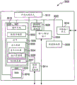
FIG. 2 is a block diagram of one embodiment of possible components of the audio converter 140 of the system of FIG. 1;
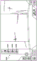
FIG. 3 illustrates an exemplary embodiment of a progression of a music compilation;
FIG. 4 is a block diagram of one embodiment of possible components of the soundtrack partitioner 204 of the system of FIG. 2;
FIG. 5 is an exemplary spectral diagram illustrating a frequency distribution of an audio input having a fundamental frequency and a plurality of harmonics;
FIG. 6 is an exemplary pitch versus time graph illustrating the pitch of a human voice that varies between a first and second pitch and is then positioned around the second pitch;
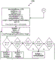
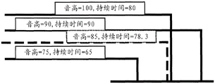
FIG. 7 is an exemplary embodiment of a morphology plotted as pitch events versus time, each pitch event having a discrete duration;
FIG. 8 is a block diagram illustrating the contents of a data file in one embodiment of the invention;
FIG. 9 is a flow diagram illustrating one embodiment of a method for generating a music track within a continuous loop of recorded accompaniment;
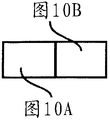
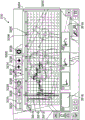
10, 10A and 10B together form an illustration of one possible user interface for generating a music track within a continuous loop of recorded accompaniment;
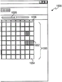
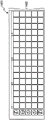
FIG. 11 is an illustration of one possible user interface for a calibration recording accompaniment;
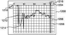
12A, 12B, and 12C together illustrate a second possible user interface associated with the generation of a music track within a continuous loop of recorded accompaniment at three separate time periods;
13A, 13B and 13C together illustrate one possible use of a user interface for modifying a music track input into a system using the user interface of FIG. 12;
14A, 14B, and 14C together illustrate one possible user interface for creating a rhythm audio track at three separate time periods;
FIG. 15 is a block diagram of one embodiment of possible components of MTAC module 144 of the system of FIG. 1;
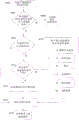
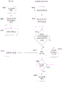
FIG. 16 is a flow chart illustrating one possible process for determining the musical key reflected by one or more notes of an audio input;
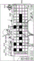
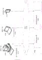
FIG. 16A illustrates a interval distribution matrix that may be used to better determine tone-symbols;
16B and 16C illustrate a minor key and a minor key interval distribution matrix, respectively, used in association with the interval distribution matrix to provide preferred tone-symbol determinations;
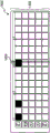
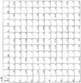
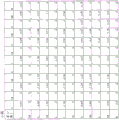
17, 17A and 17B together form a flow diagram illustrating one possible process for scoring portions of a music track based on chordal sequence constraints;
FIG. 18 illustrates one embodiment of a process for determining the centroid of a morphology;
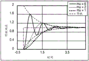
FIG. 19 illustrates a step response of a harmonic oscillator over time, with a damped response, an over-damped response, and an under-damped response;
FIG. 20 illustrates a logic flow diagram to show one embodiment for scoring portions of a musical input;
FIG. 21 illustrates a logic flow diagram for one embodiment of a process for composing a "best" track from a plurality of recording tracks;
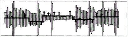
FIG. 22 illustrates one embodiment of an exemplary audio waveform and graphical representation of a score showing the difference in actual pitch from ideal pitch;
FIG. 23 illustrates one embodiment of a new audio track made up of partitions of previously recorded audio tracks;
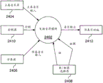
FIG. 24 illustrates a data flow diagram showing one embodiment of a process for harmonizing an accompaniment music input with a master music input;
FIG. 25 is a data flow diagram illustrating the process performed by the transform notes module of FIG. 24;
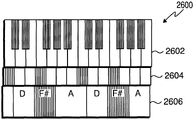
FIG. 26 illustrates an exemplary embodiment of a super keyboard;
27A-B illustrate two exemplary embodiments of a chord wheel;
FIG. 28 illustrates one exemplary embodiment of a network configuration in which the present invention may be implemented;
FIG. 29 illustrates a block diagram of a device that supports the processes discussed herein;
FIG. 30 illustrates one embodiment of a music network device;
FIG. 31 illustrates one possible embodiment of a first interface in a gaming environment;
FIG. 32 illustrates one possible embodiment of an interface for creating one or more master vocal or instrument tracks in the gaming environment of FIG. 31;
FIG. 33 illustrates one possible embodiment of an interface for creating one or more percussion instrument tracks in the gaming environment of FIG. 31;
34A-C illustrate a possible embodiment of an interface for creating one or more accompaniment tracks in the gaming environment of FIG. 31;
FIG. 35 illustrates one possible embodiment of a graphical interface depicting the progression of chords played as an accompaniment to a dominant music;
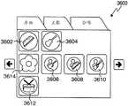
FIG. 36 illustrates one possible embodiment for selecting among different segments of a music compilation in the gaming environment of FIG. 31;
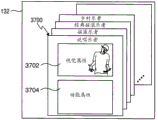
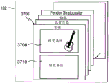
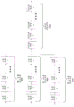
FIGS. 37A and 37B illustrate a possible embodiment of a file structure associated with a music asset that may be utilized in connection with the gaming environment of FIGS. 31-36;
FIG. 38 illustrates one embodiment of a presentation cache in accordance with the present invention;
FIG. 39 illustrates one embodiment of a logic flow diagram for one embodiment of obtaining audio for a requested note in accordance with the present invention;
FIG. 40 illustrates one embodiment of a flow diagram for implementing the cache control process of FIG. 39, in accordance with the present invention;
FIG. 41 illustrates one embodiment of an architecture for implementing a presentation cache in accordance with the present invention;
FIG. 42 illustrates a second embodiment of an architecture for implementing a presentation cache in accordance with the present invention;
FIG. 43 illustrates one embodiment of a signal diagram that illustrates communication between a client, a server, and an edge cache in accordance with the present invention;
FIG. 44 illustrates a second embodiment of a signal diagram illustrating communication between a client, a server, and an edge cache, according to an embodiment of the invention;
FIG. 45 illustrates an embodiment of a first process for optimizing an audio request processing queue according to the present invention;
FIG. 46 illustrates an embodiment of a second process for optimizing an audio request processing queue according to the present invention;
FIG. 47 illustrates an embodiment of a third process for optimizing an audio request processing queue according to the present invention;
FIG. 48 illustrates an exemplary embodiment of a live play loop according to an embodiment of the present invention;
FIG. 49 illustrates one embodiment of a series of effects that may be applied to a music compilation in accordance with the present invention;
FIG. 50 illustrates one embodiment of a series of musician character effects that can be applied to an instrument track in accordance with the present invention;
FIG. 51 illustrates one embodiment of a series of producer character effects that may be applied to musical instrument tracks in accordance with the present invention;
fig. 52 illustrates one embodiment of a series of producer character effects that may be applied to a compilation track in accordance with the present invention.
Detailed Description
The present invention now will be described more fully hereinafter with reference to the accompanying drawings, which form a part hereof, and which show, by way of illustration, specific exemplary embodiments by which the invention may be practiced. This invention may, however, be embodied in many different forms and should not be construed as limited to the embodiments set forth herein; rather, these embodiments are provided so that this disclosure will be thorough and complete, and will fully convey the scope of the invention to those skilled in the art. The present invention may be embodied as, among other things, methods or devices. Accordingly, the present invention may take the form of an entirely hardware embodiment, an entirely software embodiment or an embodiment combining software and hardware aspects. The following detailed description is, therefore, not to be taken in a limiting sense.
And (4) defining.
Throughout the specification and claims, the following terms take the meanings explicitly associated herein, unless the context clearly dictates otherwise. The phrase "in one embodiment" as used herein does not necessarily refer to the same embodiment, although it may. Moreover, the phrase "in another embodiment" as used herein does not necessarily refer to a different embodiment, although it may. Thus, as described below, various embodiments of the present invention may be readily combined without departing from the scope or spirit of the present invention.
Further, as used herein, the term "or" is an inclusive "or" operator, and is equivalent to the term "and/or," unless the context clearly dictates otherwise. The term "based on" is not exclusive and allows for being based on additional factors not described, unless the context clearly dictates otherwise. Furthermore, throughout the specification, the meaning of "a", "an" and "the" includes plural references. The meaning of "in … …" includes "in … …" and includes plural references. The meaning of "in … …" includes "in … …" and "on … …".
As used herein, the term "music input" refers to any signal input containing music and/or control information transmitted over a variety of media including, but not limited to, air, microphones, in-line mechanisms, and the like. The music input is not limited to the frequency of signal input that may be heard by the human ear, and may include other frequencies beyond those that may be heard by the human ear or in a form that is not readily heard by the human ear. Furthermore, the use of the term "musical" is not intended to convey an inherent need for tempo, rhythm, or the like. Thus, for example, a musical input may include various inputs such as taps (including single taps), taps, human inputs such as speech (e.g., do, re, mi), percussive inputs (e.g., ka, cha, da-da), etc., as well as indirect inputs via transmission through musical instruments or other amplitude and/or frequency generation mechanisms, including but not limited to microphone inputs, line-in inputs, MIDI inputs, files with signal information usable to convey musical inputs, or other inputs that enable transmitted signals to be converted to music.
As used herein, the term "musical key" is a harmonious set of musical notes. The pitch is usually major or minor. Musicians frequently talk about a piece of music as C major "key", which implies, for example, that a piece of music harmonically centers on note C and utilizes a major scale with the first note or key as C. A major scale is an octave progression made up of complete and large semitones (e.g., C D E F G a B or do re mifa so la ti). With respect to pianos, for example, the center C (sometimes referred to as "C4") has a frequency of 261.626Hz, while D4 is 293.665 Hz; e4 is 329.628 Hz; f4 is 349.228 Hz; g4 is 391.995 Hz; a4 is 440.000 Hz; and B4 is 493.883 Hz. Although the same note on other instruments will be played at the same frequency, it is also understood that some instruments play in one tone or another.
As used herein, the term "inharmonious note" is a note that is not in the correct musical tone or string, where the correct musical tone and correct string are the musical tones or strings currently being played by another musician or music source.
As used herein, the term "blue note" is a note that is not in the correct musical key or string but is allowed to play without transformation.
As used herein, the term "notes of the accompaniment music input" is notes performed by the accompanying player in association with notes performed in the corresponding theme melody.
General description of the invention.
Various embodiments are briefly described below to provide a basic understanding of some aspects of the invention. This brief description is not intended as a comprehensive overview. It is not intended to identify key or critical elements or to delineate or otherwise narrow the scope. Its sole purpose is to present some concepts in a simplified form as a prelude to the more detailed description that is presented later.
Briefly, various embodiments are directed to generating a multi-track recording by looping through a set of previously recorded audio tracks and receiving audible input for each added audio track. In one embodiment, each audio track in a multi-track recording may be generated from audible vocal input from an end user. Each new audible input may be provided after repeated playback of the current recording, or cycled one or more times. This recording sequence, separated by a loop period during which no new audio track input is received, may allow the user to listen to the current recording thoroughly, continuously, and without the time-dependent stress of additional input being immediately required. Regardless of the loop in which the additional audio track is input, playback of the loop may also allow other actions to be performed, such as modifying a previous audio track or changing parameters of the recording system.
Further, at least one of the audio tracks in the multi-track recording may include one or more instrument sounds generated based on one or more different sounds provided in the audible input. Various forms of processing may be performed on the received audible input to create an audio track, including alignment and adjustment of the timing of the audible input, frequency identification and adjustment, conversion of the audible input to a timbre associated with the instrument, addition of known auditory cues associated with the instrument, and so forth. Further, each of these processes may be performed in real-time, allowing for near instantaneous playback of the generated audio track, and enabling immediate and subsequent receipt of another audible input for processing and overlaying as an audio track onto one or more previously recorded tracks in a multi-track recording.
In one embodiment, the loop or repeated portion of the multi-track recording may include a single piece of music. The length of the bar may be determined by the tempo and time signature (time signature) associated with the track. In another embodiment, the number of bars or loop points of playback of a multi-track recording may be dynamic. That is, the repetition of a first audio track in a multi-track recording may occur at a different time than the time of a second audio track in the multi-track recording. The adjustment of the dynamic loop point may be determined automatically, for example, based on the length of audible input for a subsequent audio track.
Various embodiments are also directed to automatically making a single "best" curve segment from a series of curve segments. In one embodiment, a plurality of episodes of a performance are recorded onto a multi-track recorder during one or more accompaniments. Each curve segment is automatically partitioned into segments. The quality of each partition of each of the plurality of curved segments is scored based on a selectable criterion, and the audio track is automatically constructed from the best quality segment of each curved segment. In one embodiment, the best segment is defined by the segment having the highest score from among the plurality of segment scores.
Various embodiments are further directed to protecting musicians from playing anharmonic notes. In one embodiment, notes of the accompanying instrument are received and from the master instrument. The notes from the accompanying instruments are then modified based on the pitch, strings, and/or timing of the key. In one embodiment, a virtual instrument may be provided in which the input tones of the instrument are dynamically mapped onto the safety notes. Thus, if a player of the virtual instrument accompanies the melody, the virtual instrument may identify safe notes including notes for the current string of the melody being accompanied or notes in the tone of the melody.
A device architecture.
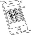
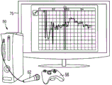
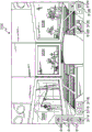
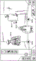
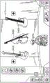
FIG. 1 shows one embodiment of a system 100 that may be deployed on a variety of devices 50, and for purposes of illustration, the devices 50 may be any general purpose computer (FIG. 1A), handheld computing device (FIG. 1B), and/or dedicated gaming system (FIG. 1C). The system 100 may be deployed as an application installed on the device. Alternatively, the system may operate within an http browser environment, which may optionally utilize web plug-in technology to extend the functionality of the browser to implement the functionality associated with the system 100. The device 50 may include more or fewer components than those shown in fig. 29. However, those skilled in the art will appreciate that certain components are not necessary to operate the system 100, and other components such as a processor, microphone, video display, and audio speaker are important if not necessary to practice aspects of the invention.
As shown in fig. 29, device 50 includes a processor 2902, which processor 2902 may be a CPU that communicates with a mass storage 2904 via a bus 2906. The processor 2902 may also include one or more general purpose processors, digital signal processors, other special purpose processors, and/or ASICs, alone or in combination with each other, as will be appreciated by those skilled in the art upon review of the present specification, drawings, and claims. The device 50 also includes a power supply 2908, one or more network interfaces 2910, an audio interface 2912, a display driver 2914, a user input processing program 2916, an illuminator 2918, an input/output interface 2920, an optional tactile interface 2922, and an optional Global Positioning System (GPS) receiver 2924. The device 50 may also include a camera (not shown) that enables video to be acquired and/or associated with a particular multi-track recording. Video from a camera or other source may further be provided to an online social network and/or an online music community. Device 50 may also optionally communicate with a base station (not shown) or directly with another computing device. Other computing devices, such as base stations, may include additional audio-related components, such as a specialized audio processor, generator, amplifier, speakers, XLR connectors, and/or power supply.
Continuing with fig. 29, the power source 2908 can include rechargeable or non-rechargeable batteries, or can be provided by an external power source (such as an AC adapter or powered docking cradle that can also supplement and/or recharge the batteries). Network interface 2910 includes circuitry for coupling device 50 to one or more networks and is constructed for use with one or more communication protocols and techniques, including but not limited to: global system for mobile communications (GSM), Code Division Multiple Access (CDMA), Time Division Multiple Access (TDMA), User Datagram Protocol (UDP), transmission control protocol/internet protocol (TCP/IP), SMS, General Packet Radio Service (GPRS), WAP, Ultra Wideband (UWB), IEEE 802.16 worldwide interoperability for microwave access (WiMax), SIP/RTP, or any of a variety of other wireless communication protocols. Accordingly, the network interface 2910 may include a transceiving device or a Network Interface Card (NIC) as a transceiver.
The audio interface 2912 (fig. 29) is arranged to generate and receive audio signals, such as the sound of a human voice. For example, as best shown in fig. 1A and 1B, audio interface 2912 may be coupled to a speaker 51 and/or microphone 52 to enable music output and input into system 100. The display driver 2914 (fig. 29) is arranged to generate video signals to drive various types of displays. For example, the display driver 2914 may drive the video surveillance display 75 shown in fig. 1A, the video surveillance display 75 may be a liquid crystal, gas plasma, or Light Emitting Diode (LED) based display or any other type of display usable with a computing device. As shown in fig. 1B, the display driver 2914 may alternatively drive a handheld touch sensitive screen 80, the handheld touch sensitive screen 80 will also be arranged to receive input from an object such as a stylus or a number from a human hand via the user input handler 2916 (see fig. 31). Keypad 55 may include any input device (e.g., keyboard, game controller, trackball, and/or mouse) arranged to receive input from a user. For example, keypad 55 may include one or more buttons, numeric dials, and/or keys. Keypad 55 may also include command buttons associated with selecting and sending images.
As shown in FIG. 29, the mass storage 2904 includes a RAM 2924, a ROM 2926, and other storage devices. Mass memory 2904 illustrates examples of computer-readable storage media for storing information such as computer-readable instructions, data structures, program modules or other data. The mass memory 2904 stores a basic input/output system ("BIOS") 2928 used to control low-level operation of the device 50. The mass memory also stores an operating system 2930, a messenger 2934, a browser 2936, and other applications 2938 for controlling the operation of the device 50. It will be appreciated that the component may comprise a general-purpose operating system (such as a version of MAC OS, WINDOWS, UNIX, LINUX) or a special-purpose operating system (such as, for example, Xbox 360 System software, Wii IOS, Windows MobileTM, iOS, Android, webOS, QNX, or Symbian @. operating system). The operating system may include or interface with a Java virtual machine module that enables control of hardware components and/or operating system operations via Java application programs. The operating system may also include a secure virtual container, also commonly referred to as a "sandbox," that enables applications (e.g., Flash and Unity) to be securely executed.
One or more data storage modules 132 may be stored in memory 2904 of device 50. Portions of the information stored in the data storage module 132 may also be stored on a disk drive or other storage medium associated with the device 50, as will be appreciated by those skilled in the art upon review of the present specification, drawings, and claims. These data storage modules 132 may store multi-track recordings, MIDI files, WAV files, audio data samples, and a variety of other data and/or data formats or input melody data having any of the formats discussed above. The data storage module 132 may also store information describing various capabilities of the system 100, which may be sent to other devices, e.g., as part of a header during a communication, upon request, or in response to a particular event, etc. In addition, the data storage module 132 may also be employed to store social networking information including address books, friends lists, aliases, user profile information, and the like.
Applications on device 50 may also include a messenger 132 and a browser 134. The messenger 132 may be configured to initiate and manage messaging sessions using any of a variety of messaging communications including, but not limited to, email, Short Message Service (SMS), Instant Message (IM), Multimedia Message Service (MMS), Internet Relay Chat (IRC), mrrc, RSS feeds, and the like. For example, in one embodiment, the messenger 132 may be configured as an IM messaging application, such as an AOL instant messenger, Yahoo! messenger,. NET messenger server, ICQ, or the like. In another embodiment, the messenger 132 may be a client application configured to integrate and employ multiple messaging protocols. In one embodiment, the messenger 132 may interact with the browser 134 to manage messages. Browser 134 may include virtually any application configured to receive and render graphics, text, multimedia, and the like, in virtually any web-based language. In one embodiment, the browser application is enabled to employ Handheld Device Markup Language (HDML), Wireless Markup Language (WML), WMLScript, JavaScript, standard generalized markup language (SMGL), hypertext markup language (HTML), extensible markup language (XML), and the like, to display and send messages. However, any of a variety of other web-based languages may be employed, including Python, Java, and third party web plug-ins.
Of course, while the various applications discussed above are shown as being implemented on device 50, in alternative embodiments, one or more portions of each of these applications may be implemented on one or more remote devices or servers, with the inputs and outputs of each portion being communicated between device 50 and the one or more remote devices or servers over one or more networks. Alternatively, one or more of the applications may be packaged for execution on or downloaded from a peripheral device.
An audio transducer.
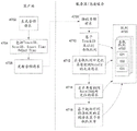
The audio converter 140 is configured to receive the audio data and convert it into a more meaningful form for use within the system 100. One embodiment of an audio transducer 140 is illustrated in fig. 2. In this embodiment, the audio converter 140 may include a variety of subsystems including a track recorder 202, a track partitioner 204, a quantizer 206, a frequency detector 208, a frequency shifter 210, an instrument converter 212, a gain controller 214, a harmonic generator 216, a special effects editor 218, and a manual adjustment controller 220. Connections to and interconnections between the various subsystems of the audio transducer 140 are not shown to avoid obscuring the invention, however, as will be understood by those skilled in the art in light of the present specification, drawings and claims, these subsystems will be electrically and/or logically connected.
The soundtrack recorder 202 enables a user to record at least one audio soundtrack from a vocal or musical instrument. In one embodiment, the user may record the track without any accompaniment. However, the track recorder 202 may also be configured to play audio automatically or upon user request, including a beat track (click track), a musical accompaniment, an initial tone against which the user may judge his/her pitch and timing, or even previously recorded audio. A "beat track" refers to a periodic clicking noise (such as that emitted by a mechanical metronome) intended to help a user maintain a consistent beat. The track recorder 202 may also enable the user to set the length of time to be recorded as a time limit (i.e., a number of minutes and seconds) or a number of music bars. When used in conjunction with MTAC module 144, as discussed below, soundtrack recorder 202 may also be configured to graphically indicate scores associated with various portions of recorded soundtracks to indicate, for example, when a user is out of tune, etc.
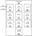
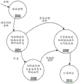
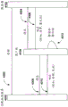
Typically, the music compilation is composed of a plurality of lyrics. For example, FIG. 3 illustrates a typical progression of popular songs, starting with a sequential song segment, followed by alternate verse and chorus segments, and a bridge segment, followed by a final verse. Of course, although not shown, other structures may be used, such as refrains, ending songs, and so forth. Thus, in one embodiment, the track recorder 202 may also be configured to enable the user to select a segment of a song for which the recorded audio track is to be used. The segments may then be arranged in any order (either automatically (based on the determination made by the type matcher module 152) or as selected by the end user) to compose a complete music compilation.
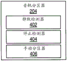
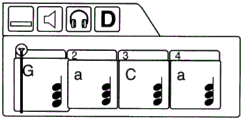
The track partitioner 204 divides the recorded audio tracks into separate partitions, which can then be addressed and potentially stored as individually addressable separate sound clips or files. The partitions are preferably chosen such that end-to-end spliced segments result in little or no audio artifacts. For example, let us assume that the audible input includes the phrase "pumpa pum". In one embodiment, the partitioning of the audible input may identify and distinguish each syllable of the audible input as a separate sound, such as "pum," pa, "and" pum. However, it should be understood that the phrase may be depicted in other ways, and that a single partition may include more than one syllable or word. Four sections (numbered "1", "2", "3" and "4") are illustrated on the display 75 in fig. 1A, 1B and 1C, each section comprising more than one syllable. As illustrated, the partition "1" has a plurality of notes that may reflect the same plurality of syllables that have been recorded by the track recorder 202 using input from the microphone 52 of a human or instrumental source.
To perform the division of the audible audio tracks into separate partitions, the audio track partitioner 204 may utilize one or more processes running on the processor 2902. In one exemplary embodiment shown in fig. 4, the audio track partitioner 204 may include a silence detector 402, a stop detector 404, and/or a manual partitioner 406, each of which may be used to partition an audio track into N partitions aligned in time. The track partitioner 204 can use the silence detector 302 to partition the track whenever silence is detected for a certain period of time. This "silence" may be defined by a volume threshold, such that when the audio volume falls below the defined threshold for a defined period of time, the location in the audio track is considered to be silent. Both the volume threshold and the time period may be configurable.
On the other hand, the stop detector 404 may be configured to use voice analysis (such as format analysis) to identify vowels and consonants in the audio track. For example, consonants (such as T, D, P, B, G, K) and nasal sounds are delimited by the blockage of airflow in their utterances. The location of a particular vowel or consonant may then be used to detect and identify points that are preferably partitioned. Similar to silence detector 402, the types of vowels and consonants utilized by stop detector 404 to identify partition points may be configurable. A manual partition 406 may also be provided to enable a user to manually delimit each partition. For example, the user may simply specify the length of time for each partition, thereby causing the audio track to be divided into a number of partitions each having equal length. The user may also be allowed to identify a specific location in the audio track where a partition is to be created. The identification may be performed graphically using a pointing device (such as a mouse or game controller) in conjunction with the type of graphical user interface shown in fig. 1A, 1B, and 1C. The identification may also be performed by pressing a button or key on a user input device, such as the keyboard 55, mouse 54, or game controller 56, during audible playback of the audio track by the track recorder 202.
Of course, while the functions of the silence detector 402, the stop detector 304, and the manual partitioner 406 have been described separately, it is contemplated that the audio track partitioner 204 may partition or divide the audio track into segments using any combination of silence detectors, stop detectors, and/or manual partitioners. Those skilled in the art will also appreciate in view of the foregoing description, drawings, and claims that other techniques for partitioning or dividing an audio track into segments may also be used.
The quantizer 206 is configured to quantize the partitions of the received audio tracks, which may utilize one or more processes running on the processor 2902. The process of quantizing (as that term is used herein) refers to the time-shifting of each previously created partition (and, therefore, the notes contained within that partition), as may be necessary to align the sound within the partition with a particular beat. Preferably, the quantizer 206 is configured to time-sequentially align the start of each partition with the previously determined beat. For example, a prosody may be provided in which each bar may include 4 beats and the alignment of the separated sounds may be made with respect to quarter-beat time increments, thereby providing 16 time points in each four-beat bar with which the partitions may be aligned. Of course, any number of increments of each bar (such as three beats for the waltz or boekard effect, two beats for the rock effect, etc.) and beat may be used, and at any time during the process, may be manually adjusted by the user or automatically adjusted based on certain criteria, such as a user selection of a particular style or type of music (e.g., blues, jazz, boekard, pop, rock, or waltz).
In one embodiment, each partition may be automatically aligned by the quantizer 206 at an available time increment at which it was most closely received at the time of recording. That is, if the sound starts between two time increments in the beat, the playback timing of the sound will be shifted chronologically forward or backward to one of the increments that is closer to its initial start time. Alternatively, each sound may be automatically shifted in time to each time increment immediately preceding the relative time at which the sound was initially recorded. In yet another embodiment, each sound may be automatically shifted in time to each time increment immediately after the relative time at which the sound was initially recorded. Alternatively or additionally, the time shift (how well) of each separate sound may also be affected based on the type selected for the multi-track recording, as discussed further below with respect to the type matcher 1252. In another embodiment, each sound may also be automatically time-aligned with a previously recorded track in a multi-track recording, thereby achieving a karaoke type effect. Further, the length of the separated sounds may be greater than one or more time increments, and the time-shifting of the quantizer 206 may be controlled to prevent the separated sounds from being time-shifted such that the separated sounds overlap within the same audio track.
To illustrate, fig. 5 depicts one example of a frequency spectrum that may result from the output of an FFT process performed on portions of a received audio track. As can be seen, the spectrum 400 includes one main peak 502 corresponding to pitch at a single fundamental frequency (F), as well as harmonics excited at 2F, 3F, 4F … … nF. There are additional harmonics in the spectrum, since when an oscillator such as a vocal cord or a violin string is excited at a single pitch, the oscillator typically vibrates at multiple frequencies.
In some instances, the identification of pitches may be complicated by additional noise. For example, as shown in fig. 5, the spectrum may include noise that appears as low amplitude spikes spread across the spectrum as a result of the audio input coming from a real-world oscillator such as a speech or musical instrument. In one embodiment, the noise may be extracted by filtering the FFT output below a certain noise threshold. In some instances, the identification of pitch may also be complicated by the presence of vibrato. Vibrato is an intentional frequency modulation that may be applied to a musical performance and is typically between 5.5Hz and 7.5 Hz. The vibrato may be filtered out of the FFT output by applying a band pass filter in the frequency domain, as in the noisy case, but filtering the vibrato may be undesirable in many situations.
In addition to the frequency domain methods discussed above, it is also contemplated that one or more time domain methods may be used to determine the pitch of one or more sounds in a partition. For example, in one embodiment, pitch may be determined by measuring the distance between zero crossings of the signal. Algorithms such as AMDF (average magnitude difference function), ASMDF (average mean square difference function), and other similar autocorrelation algorithms may also be used.
To make the determination of pitch most efficient, the pitched content can also be grouped into notes (of constant frequency) and glides (of steadily increasing or decreasing frequency). However, unlike musical instruments having frets or keys that naturally produce stable discrete pitches, human voices tend to slide into notes and rock in a continuous manner, making conversion to discrete pitches difficult. Thus, the frequency detector 208 may also preferably utilize pitch pulse detection to identify shifts or changes in pitch between the separate sounds within the partition.
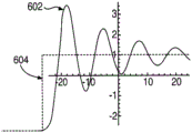
Pitch pulse detection is a method for delimiting pitch events that are focused on the trajectory of the control loop formed between the singer's voice and his perception of his voice. Generally, when a singer utters a voice, the singer hears the voice immediately thereafter. If the singer hears a pitch that is incorrect, he immediately modifies his speech to the intended pitch. The negative feedback loop can be modeled as a damped harmonic motion driven by periodic pulses. Thus, the human voice can be viewed as a single oscillator: the vocal cords. An example illustration of the pitch shifting and placement of the singer's voice 602 can be seen in fig. 6. Tension in the vocal cords controls pitch, and this change in pitch can be modeled by a response to a step function (such as step function 604 in fig. 6). Thus, the start of a new pitch event can be determined by finding the start of damped harmonic oscillations in pitch and observing the successive turning points of the pitch that converge to a stable value.
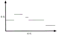
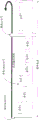
After a pitch event within a partition of an audio track has been determined, it may be converted and/or stored into a modality that is a graph of pitch events versus time. One example of a modality (without partitioning) is depicted in fig. 7. Thus, the morphology may include information identifying the onset, duration, and pitch of each sound, or any combination or subset of these values. In one embodiment, the morphology may be in the form of MIDI data, although morphology may refer to any representation of pitch versus time and is not limited to semitones or any particular prosody. For example, in the "Morphological Metrics" by Larry Polansky, incorporated herein by reference,Journal of New Music Researchother such examples of morphologies that may be used are described in volume 25, pp. 289-368, ISSN: 09929-8215.
The gain controller 214 may be configured to automatically adjust the relative volume of the audible input based on the volume of other previously recorded audio tracks and may utilize one or more processes running on the processor 2902. The harmonic generator 216 may be configured to incorporate harmonics into the audio tracks, which may utilize one or more processes running on the processor 2902. For example, different additional frequencies of the audible input signal may be determined and added to the produced audio track. Determining the additional frequency may also be based on the type from the type matcher 260 or by using other predetermined parameter settings entered by the user. For example, if the selected type is Waltz, it may be at a beat of "oom-pa-pa The additional frequency is selected in time from the major chord in the octave immediately below the dominant in harmony with the dominant music as follows: fundamental tone
 Fundamental tone
 . The
. The special effects editor 218 may be configured to add various effects to an audio track, such as echo, reverberation, and the like, preferably utilizing one or more processes running on the processor 2902.
The audio transducer 140 may also include a manual adjustment control 220 to enable a user to manually alter any settings automatically configured by the modules discussed above. For example, the manual adjustment control 220 may enable the user to alter the frequency of the audio input or portions thereof, among other options; enabling the user to alter the onset and duration of each discrete sound; increasing or decreasing the gain of the audio track; a different instrument to be applied to instrument transformer 212 is selected. The manual adjustment control 220 may be designed for use with one or more graphical user interfaces, as will be understood by those skilled in the art in light of the present specification, drawings, and claims. One particular graphical user interface will be discussed below in association with FIGS. 13A, 13B, and 13C.
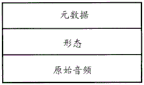
Fig. 8 illustrates one embodiment of a file structure for a partition of an audio track that has been processed by the audio converter 140 or otherwise downloaded, retrieved or obtained from another source. As shown, in this embodiment, the file includes metadata associated with the file, obtained morphology data (e.g., having a MIDI format), and raw audio (e.g., having a. wav format). The metadata may include information indicative of a profile associated with a creator or supplier of the audio track partition. It may also include additional information related to the audio signature of the data, such as the pitch, tempo, and partition associated with the audio. The metadata may also include information about the possible available pitch shifts that may be applied to each note in the partition, the amount of time shift that may be applied to each note, and so on. For example, it will be appreciated that for live recorded audio, if the pitch is shifted more than a semitone, there is a possibility of distortion. Accordingly, in one embodiment, constraints may be placed on live audio to prevent the shifting of more than one semitone. Of course, different settings and different constraints may also be used. In another embodiment, the range of possible pitch shifts, time shifts, etc. may also be altered or established by the creator of the audio track partition or any individual (such as an administrator, partner, etc.) having substantial rights in the audio track partition.
Recording the live loop of accompaniment.
The record accompaniment live loop (RSLL) module 142 implements a digital audio workstation that, in conjunction with the audio transducer 140, enables the recording of audible input, the generation of separate audio tracks, and the creation of multi-track records. Thus, the RSLL module 1422 may enable any recorded audio track (spoken, singing, or otherwise) to be combined with a previously recorded track to create a multi-track recording. The RSLL module 142 is also preferably configured to loop at least one of the previously recorded multi-track recordings for repeated playback, as discussed further below. This repeated playback may be performed while a new audible input is being recorded or the RSLL module 142 is otherwise receiving instructions for the recording accompaniment that is currently ongoing. Thus, the RSLL module 142 allows the user to continue editing and synthesizing music tracks while playing and listening to previously recorded tracks. As will be appreciated from the discussion below, the continuous loop of previously recorded audio tracks also minimizes the user's perception of any latency that may be caused by the process applied to the audio track that the user is currently recording, when such a process is preferably completed.
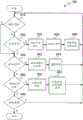
Fig. 9 illustrates a logical flow diagram generally showing one embodiment of an overview process for creating a multi-track recording using the RSLL module 142 in conjunction with the audio transducer 140. In general, the operations of FIG. 9 generally represent recording an accompaniment. Such accompaniment may be newly created and completed each time the user employs the system 100 and, for example, the RSLL module 142. Alternatively, the previous accompaniment may be continued and certain elements thereof may also be loaded and applied, such as previously recorded multi-track recordings or other user-specified recording parameters.
In either arrangement, after a start block, the process 900 begins at decision block 910 where the user determines whether to playback a currently recorded multi-track recording. The process of playing back a current multi-track recording while enabling other actions to be performed is generally referred to herein as a "live loop". The content and duration of the portion of the multi-track recording currently being played back without explicit repetition is referred to as a "live loop". During playback, a multi-track recording may be accompanied by a tempo audio track, which typically includes a separate audio track not stored with the multi-track recording that provides a series of equally spaced reference sounds or tempos that audibly indicate the speed of the audio track and bar that the system is currently configured to record.
In an initial execution of process 900, an audio track may not have been generated. In this state, playback of the empty multi-track recording in block 910 may be simulated, and the beat track may provide the only sound played back to the user. However, in one embodiment, the user may choose to have the beat tracks muted, as discussed further below with respect to block 964. Visual cues may be provided to the user in conjunction with audio playback during recording. Even when the audio track is not recorded and the tempo track is faded, the indication of the simulated playback and the current playback position can be limited to only these visual cues, which may include, for example, a display of a change in a progress bar, pointer, or some other graphical indication (see, e.g., fig. 12A, 12B, and 12C).
The multi-track recording of the live loop played back in decision block 910 can include one or more audio tracks that have been previously recorded. The multi-track recording may include an overall length and a length for playback as a live loop. The length of the live loop may be selected to be less than the overall length of the multi-track recording, allowing a user to separately layer different pieces of the multi-track recording. The length of the live loop relative to the overall length of the multi-track recording may be manually selected by the user or alternatively automatically determined based on received audible input. In at least one embodiment, the overall length of the multi-track recording and the live loop may be the same. For example, the live loop and the multi-track recording may be a single piece of music in length.
When a multi-track recording is selected for playback at decision block 910, additional visual cues, such as visual representations of one or more tracks, can be provided in synchronization with the audio playback of the live loop that includes at least the portion of the multi-track recording for user playback. While the multi-track recording is being played, process 900 continues at decision block 920 where a determination is made by the end user whether to generate an audio track of the multi-track recording. Recording may be initiated based on receiving audible input, such as vocal audible input generated by an end user. In one embodiment, the detected magnitude of the audible input may trigger sampling and storage of the audible input signal received in the system 100. In an alternative embodiment, such audio track generation may be initiated by manual input received by the system 100. Furthermore, generating a new audio track may require both a detected audible input (such as from a microphone) and a manual indication. If a new audio track is to be generated, processing continues at block 922. If generation of an audio track has not been initiated, process 900 continues at decision block 940.
At block 922, audible input is received by the track recorder 202 of the audio transducer 140 and stored in the memory 2904 in the one or more data storage modules 132. As used herein, "audible" refers to the nature of an input to device 50, wherein the input, when provided, may be heard simultaneously, naturally, and directly by at least one user without amplification or other electronic processing. In one embodiment, the length of the recorded audible input may be determined based on an amount of time remaining within a live loop when the audible input is first received. That is, the recording of audible input may end after the length of time at the end of the live loop, regardless of whether a detectable amount of audible input is still being received. For example, if the length of the loop is one at each of four beats and the receipt of audible input is first detected or triggered at the beginning of the second beat, three beats corresponding to the second, third and fourth beats of the strip may be recorded equivalent to the audible input, and therefore these second, third and fourth beats will be looped in the multi-track recording playback that is continuously processed in block 910. In such an arrangement, any audible input received after the end of a single bar may be recorded and processed as a basis for another separate track of a multi-track recording. This additional processing of separate audio tracks may be represented as separate iterations through at least blocks 910, 920, and 922.
In at least one alternative embodiment, the length of loop playback may be dynamically adjusted based on the length of audible input received at block 922. That is, the audible input may automatically result in an extension of the length of the track of the multi-track recording currently being played back in block 910. For example, if additional audible input is received after the length of the current live loop has been played back, the longer audible input may be further recorded and maintained to be derived as a new audio track. In such an arrangement, previous tracks of the multi-track recording may be repeated within a subsequent live loop to match the length of the received audible input. In one embodiment, an integer number of repetitions of a shorter previous multitrack recording may be performed. This integral number of repetitions maintains the relationship, if any, between the bars of the previously recorded shorter multitrack recording. In this way, the loop point of multi-track recordings and live loops can be dynamically altered.
Similarly, the length of the audio track received at block 922 may be shorter than the length of the currently playing live loop (i.e., receiving audible input of only one bar during playback of four long live loops). In such an arrangement, an end of the audible input may be detected when additional audible input has not been received after a predetermined time (e.g., a selected number of seconds) after receipt and recording of the audible input of at least the threshold volume. In one embodiment, the detection of this silence may be based on the absence of input above a threshold volume for the current live cycle. Alternatively or additionally, the end of the audible input may be signaled by the receipt of a manual signal. The associated length of the shorter audible input may be determined in terms of the number of bars having the same number of beats as the multi-track recording. In one embodiment, this number of bars is selected as a factor of the length of the current live loop. In each case, once converted to a track at block 924, the audible input may be manually or automatically selected to repeat a number of times sufficient to match the length of the multi-track recording currently being played back.
In block 924, the received audible input may be converted to an audio track by the audio converter 140. As discussed above, the audio conversion process may include various operations including partitioning, quantization, frequency detection and shifting, instrument conversion, gain control, harmonic generation, adding special effects, and manual adjustment. The order of each of these audio conversion operations may be altered and, in at least one embodiment, may be configured by the end user. Further, each of these operations may be selectively applied, enabling conversion of audible input to an audio track with as much or as minimal additional processing as needed. For example, instrument conversions may not be selected, allowing one or more original sounds from the audible input to be substantially included in the generated audio track with its original timbre. In block 924, an echo cancellation process may be applied to filter out audio of other tracks played during a live loop from an actively recorded audio track. In one embodiment, this may be accomplished by: identifying an audio signal played during a live loop; determining any delay between the output audio signal and the input audio signal; filtering and delaying the output audio signal to be similar to the input audio signal; and subtracting the output audio signal from the input audio signal. One preferred echo cancellation procedure that may be used is that implemented by iztope, although other implementations may also be used. The process of block 924 may then be applied or removed, as discussed further herein with respect to block 942. After converting the audible input to the generated audio track at block 924, the process 900 continues at block 926.
At block 926, the generated audio track from block 924 may be added to the multi-track recording in real-time. This may be a multi-track already initiated or alternatively this may be a new multi-track with an audio track included as its first track. After block 926, the process 900 may begin again at decision block 910, where multiple tracks may be played back with the included most recently generated audio track. Although operations 922, 924, and 926 are shown as being performed serially in fig. 9, these steps may also be performed in parallel for each received audible input to further enable real-time recording and playback of the audible input signals. Such parallel processing may be performed, for example, for each separate sound identified from the audible input during each audible input, although alternative embodiments may include other differently sized portions of the audible input signal.
At decision block 940, a determination is made whether one or more audio tracks in the multi-track recording are to be modified. For example, input may be received indicating an end user desire to modify one or more previously recorded audio tracks. In one embodiment, the indication may be received through manual input. As mentioned above, the modification may also be performed during playback of a currently recorded multi-track recording, thereby allowing an immediate evaluation of the current state of the multi-track recording for the end user. In one embodiment, the indication may include one or more tracks of the multi-track recording to which it is desired to apply the adjustment. These tracks may also include one or more new tracks that are manually added to the multi-track recording. If an indication of a track modification is received, process 900 continues at block 942; otherwise, process 900 continues at decision block 960.
At block 942, parameters for one or more previously converted audio tracks are received and adjusted parameters may be input by the end user. The modified parameters may include any adjustments that may be done using the process of the audio converter 140, which may include, among other examples, fading or soloise the track, removing the entire track, adjusting the strike speed of instruments in the track, adjusting the volume level of the track, adjusting the tempo of playback of all tracks in the live loop, adding or removing separate sounds from selected time increments of the track, adjusting the length of the live loop, and/or the overall length of the multi-track recording. Adjusting the length of the live loop may include: altering the start and end points of the loop with respect to the overall multi-track recording, and/or may also include adding more tracks to the track currently being repeated in the live loop, adding and/or appending previously recorded strips of the multi-track recording (where at least a subset of the tracks were previously associated with the strips), or deleting strips from the multi-track recording. The addition of a new audio track may require that aspects of the new audio track be manually entered by the end user. Further at block 942, additional tracks may be searched for by using the sound searcher module 150 to facilitate reuse of previously recorded audio tracks by the end user.
At block 944, the adjusted parameters are applied to the one or more audio tracks indicated at decision block 940. The applying may include converting the adjusted parameters to a format compatible with the adjusted one or more audio tracks. For example, one or more numerical parameters may be adjusted to correspond to one or more values suitable for use in a MIDI or other protocol format. Following block 944, the process 900 may begin again at decision block 910, where at least the portion of the multi-track recording corresponding to the live loop may be played back utilizing the included one or more modified audio tracks.
At decision block 960, a determination is made whether the record settings are to be modified. For example, input may be received indicating whether a user desires to modify one or more aspects of record settings. The indication may also be received by a manual input. The indication may advance one or more parameter settings for the record settings to be adjusted. If the end user desires to modify the recording step, process 900 continues at block 962; otherwise, process 900 continues at decision block 980.
At block 962, the recording system may be calibrated. In particular, recording circuitry including at least an audio input source, an audio output source, and audio track processing components may be calibrated to determine, in conjunction with device 50, a latency of system 100, preferably measured in thousands of seconds between playback of sound through the audio output source and receipt of audible input through the audio input source. For example, if the recording circuitry includes headphones and a microphone, the latency may be determined by the RSLL142 to improve the reception and conversion of audible input, particularly the determination of the relative timing between the beats of a multi-track recording being played back and the received audible input. After calibration (if any) at block 962, the process 900 continues to block 964.
At block 964, other recording system parameter settings may be changed. For example, playback of the beat audio track may be turned on or off. In addition, default settings for a new track or new multi-track recording may be modified, such as a default tempo and default transition set that may provide audible input for block 924. The beat number of the current multi-track recording may also be changed at block 964. Other settings associated with the digital audio workstation may also be provided such that these other settings may be modified by the end user, as will be understood by those skilled in the art in light of the present specification, drawings and claims. After block 964, process 900 may return to decision block 910 where adjustments to the recording system may be applied to subsequent recordings and modifications of audio tracks of the multi-track recording.
At block 980, a determination is made whether to end recording the accompaniment. For example, an input indicating an end of the accompaniment may be received from a manual input. Alternatively, the device 50 may initiate the ending of the accompaniment if, for example, the data storage 132 is full. If an end of accompaniment indication is received, multiple track recordings may be stored and/or transmitted for additional operations. For example, multi-track records may be stored in the data store 132 for future retrieval, review and modification in a persistent or new accompaniment of the accompaniment that initially created the multi-track record. The multi-track record may also be transmitted from the device 50 to another device 50 over a network for storage in at least one remote data store associated with the user account. The transmitted multi-track recording may also be shared with the online music community through a web server, or may be shared in a game hosted by a web server.
If recording the accompaniment is not complete, the process 900 returns again to decision block 910. Such a sequence of events may represent a period of time during which the user is listening to the live loop while deciding which, if any, additional audio tracks are to be generated or other modifications, if any, are to be performed. Those skilled in the art will appreciate that each block of the flowchart illustration in fig. 9 (or in other ways) and combinations of blocks in the flowchart illustration can be implemented by computer program instructions when the description, drawings and claims are in front of them. These program instructions may be provided to a processor to produce a machine, such that the instructions, which execute on the processor, create means for implementing the actions specified in the flowchart block or blocks. The computer program instructions may be executed by a processor to cause a series of operational steps to be performed by the processor to produce a computer-implemented process such that the instructions, which execute on the processor, provide steps for implementing the actions specified in the flowchart block or blocks. The computer program instructions may also cause at least some of the operational steps illustrated in the blocks of the flowchart to be performed in parallel. Further, some of the steps may also be performed across more than one processor, such as may occur in a multi-processor computer system. Furthermore, one or more blocks or combinations of blocks in the flowchart illustrations may also be performed in a different order than illustrated or even combined with other blocks or combinations of blocks without departing from the scope or spirit of the present invention. Accordingly, blocks of the flowchart illustrations support combinations of means for performing the specified actions, combinations of steps for performing the specified actions and program instruction means for performing the specified actions. It will also be understood that each block of the flowchart illustrations, and combinations of blocks in the flowchart illustrations, can be implemented by special purpose hardware-based systems which perform the specified actions or steps, or by combinations of special purpose hardware and computer instructions.
The operation of certain aspects of the present invention will now be described with respect to various screen displays that may be associated with a user interface implementing the audio transducer 140 and RSSL module 142. The illustrated embodiment is a non-limiting, non-exhaustive example user interface that may be employed in association with the operation of the system 100. Various screen displays may include many more or fewer components than those shown. Further, the arrangement of components is not limited to that shown in these displays, and other arrangements are also contemplated, including the provision of various components on different interfaces. However, the components shown are not sufficient to disclose an illustrative embodiment for practicing the present invention.
Fig. 10, 10A, and 10B together illustrate one user interface that implements aspects of the RSLL142 and audio transducer 140 to record and modify audio tracks of a multi-track recording. The overall display of interface 1000 may be considered a "control space". Each control displayed on the interface may be operated based on manual input from the user, such as by using a mouse 54, touch screen 80, pressure pad, or device arranged to respond to and communicate physical controls. As shown, the interface 1000 displays various aspects of a recording accompaniment and a multi-track recording generated as part of the accompaniment. The file menu 1010 includes operations for creating a new multi-track recording or loading a previously recorded multi-track recording, as will be understood by those skilled in the art in light of the present specification, drawings, and claims.
The tempo control 1012 displays the tempo of the multi-track recording in beats per minute. The tempo control 1012 may be manually modified directly by the user. The bar control 1014 displays the number of bars of the multi-track recording. The bar control 1014 may be configured to display the current number of bars during the live loop, the overall number of bars, or alternatively a specific number of bars that may be used to select a multi-track recording for further display in the interface 1000.
The beat control 1016 displays the number of beats of the multi-track recording. The beat control 1016 may be configured to display the total number of beats per bar, or alternatively the current number of beats during playback of a multi-track recording. Time control 1018 displays the time of the multi-track recording. The time control 1018 may be configured to display the overall time of the multi-track recording, the length of time of the currently selected live loop, absolute or relative times during the live loop, or a specific absolute time that may be used to skip to the multi-track recording. The operation of the controls of interface 1000, such as controls 1012, 1014, 1016, 1018, and 1021 along with 1026, may be changed in block 964 of fig. 9. Controls 1020 correspond to the track and record setting adjustments discussed further with respect to blocks 942 and 962 of fig. 9.
The add track control 1021 enables a user to manually add a track to a multi-track recording. Upon selection of control 1021, a new track is added to the multi-track recording and the interface is updated to include additional controls 1040- "1054 for the added track, the operation of which is discussed below. The presentation WAV control 1022 generates and stores a WAV file from at least a portion of the multi-track recording. The portion of the multi-track recording presented in the WAV file, as well as other storage parameters, may be further input by the user upon selection of presentation WAV control 1022. Further, other audio file formats may be available through controls such as control 1022 in addition to WAV.
The tempo track control 1023 switches playback of the tempo track. Arm control 1024 switches on and off the recording components of RSLL142 and the device's ability to record audible input. Arm control 1024 enables the end user to speak with other users, make vocal inputs, and create other audible sounds during recording of the accompaniment without converting these sounds into audible inputs for further processing by RSLL 142.
A grid 1050 on the user interface 1000 represents playback and timing of separate sounds within one or more tracks of a multi-track recording, where each row represents an individual track and each column represents a time increment. Each row may, for example, comprise a box for each time increment in a single bar. Alternatively, each row may include enough boxes to represent a time increment of the overall duration of the live loop. Boxes in the grid 1050 having a first shade or color (such as box 1052) may represent relative timing at the location where sound is played back during a live loop, while each of the other boxes (such as box 1054) indicate a time increment within the audio track where no separate sound is played back. The audio track added via manual control 1021 initially includes a box such as box 1054. Selection of a box (such as box 1052 or box 1054) may add or remove sound from the audio track at a time increment associated with the selected box. The sounds added via manual input to the boxes in the grid 1050 may include a default sound of an instrument selected for the audio track, or alternatively a copy of at least one sound quantized from audible input of the audio track. This manual operation of the grid 1050 enables audible input to generate one or more sounds of an audio track, yet adds a copy of one or more of these sounds at a manually selected location within the audio track.
The progress bar 1056 visually indicates the time increment of the current playback position of the multi-track recording. Each track in the grid 1050 is associated with a set of track controls 1040, 1042, 1044, 1046, and 1048. The remove audio track control 1040 enables removal of an audio track from a multi-track recording and may be configured to selectively remove an audio track from one or more strips of the multi-track recording.
The instrument selection control 1042 enables selection of an instrument to which to convert the sound of the audible input in the generated audio track. As shown in fig. 10A, a variety of instruments including percussion instruments or other types of non-percussion instruments may be manually selected from a drop-down menu. Alternatively, a default instrument or default instrument progression may be automatically selected or predetermined for each given audio track. When no instrument is selected, each sound in the generated audio track may substantially correspond to the sound of the original audible input included with the timbre of the initial audible input. In one embodiment, the instrument may be selected based on training the RSLL142 to automatically convert a particular sound of the audible sounds to an associated instrument sound based on, for example, a classification of the frequency band of each particular sound.
The mute/solo control 1044 mute the associated track or mute all other tracks except the track associated with the control 1044. The speed control 1046 enables adjustment of the initial attack (attack) or percussion intensity of the instrument sound generated for the converted audio track, which may affect the peak, duration, release, and overall amplitude shape of each instrument sound generated for the associated audio track. Such velocities may be manually input or alternatively extracted based on properties of audible input sounds from which one or more instrument sounds are generated. The volume control 1048 enables individual control of the playback volume of each track in the multi-track recording.
FIG. 11 illustrates one embodiment of an interface 1100 for calibrating a recording circuit. Interface 1100 may represent one example of a screen display pop-up window or the like that may appear when control 1025 (see FIG. 10A) is selected. In one embodiment, interface 1100 includes a microphone gain control 1110 that enables adjustment of the amplitude of received audible input. The upper and lower controls 1120, 1130 and the half-life control 1140 provide additional control and validation for recognizing the received signal as audible input for further processing by the system 100. Calibration circuit 1150 initiates a predetermined tempo audio track and can guide the user to reproduce the tempo audio track in the audible input signal. In an alternative embodiment, the beat audio track used for calibration may be received directly as audible input by an audio input device, such as a microphone, without the user audibly reproducing the beat audio track. Based on the relative timing difference between the generation of sound in the beat audio track and the receipt of sound in the audible input, a system latency 1160 may be determined. This latency value may be further employed by the RSLL142 to improve the quantization of audible input and the detected relative timing between playback of the multi-track recording and the audible input received for subsequent derivation of additional audio tracks to be added to the multi-track recording.
Thus, as illustrated, interfaces 1100 and 1110 present the user with an enthusiasm and non-threatening, powerful and consistent, yet intuitive control space in learning, which is particularly important to lay users who are not professional or otherwise unfamiliar with digital audio authoring tools.
12A, 12B, and 12C together illustrate yet another exemplary visual display that may be used in association with the recording and modification of audio tracks in a multi-track recording. In this example, the audio (actual and morphological (post-frequency shifting by frequency shifter 210)), zoning, quantization and tempo information is provided graphically to provide an even more intuitive experience to the user. For example, turning first to FIG. 12A, a graphical control space 1200 for a live loop is provided. The control space includes a plurality of partition indicators 1204 that identify each of the partitions (or music measures) (in the case of fig. 12A-C, measures 1 through 4 are shown) in the audio track. In one embodiment of the graphical user interface shown in fig. 12A-C, vertical lines 1206 illustrate beats within each bar, where the number of vertical lines per bar preferably corresponds to the top number of the beat sign. For example, if a piece of music is selected to be composed using 3/4 beat marks, each bar will include three vertical lines to indicate that there are three beats in the bar or section. In the same embodiment of the user interface shown in fig. 12A-C, horizontal line 1208 may also identify the fundamental frequency associated with the selected instrument to which the audible input is to be converted. As further illustrated in the embodiment of FIGS. 12A-C, an instrument icon 1210 can also be provided to indicate a selected instrument, such as the selected guitar in FIGS. 12A-C.
In the embodiment shown in fig. 12A-C, solid line 1212 represents an audio waveform of one track as recorded by the end user with vocal or using an instrument; and a plurality of horizontal bars 1214 represent the morphology of notes that have been generated from the audio waveform by the quantizer 206 and frequency shifter 210 of the audio converter 140. As depicted, each note of the generated morphology has been shifted in time to align with the beat of each section and in frequency to correspond to one of the fundamental frequencies of the selected instrument.
As depicted by comparing fig. 12A with fig. 12B with fig. 12C, a playback bar 1216 may also be provided to identify a particular portion of the live loop currently being played by the track recorder 202 in relation to the process of fig. 9. Thus, the playback bar 1216 is moved from left to right as the live loop is played. Upon reaching the end of the fourth bar, the playback bar returns to the beginning of bar 1 and repeats the cycle again sequentially. The end user may provide additional audio input at any point within the live loop by recording the additional audio at the appropriate point in the loop. Although not shown in fig. 12A-C, each additional recording may be used to provide a new track (or set of notes) to depict within the live loop. Separate tracks may be associated with different instruments by adding additional instrument icons 1210.
13A, 13B, and 13C together illustrate one example of a process for manually altering a previously generated note via the interfaces of FIGS. 12A-C. As shown in fig. 13A, the end user can select a particular note 1302 using a pointer 1304. As shown in fig. 13B, the end user may then drag the note vertically with another horizontal line 1208 to alter the pitch of the dragged note. In this example, note 1302 is shown as being moved to a higher fundamental frequency. It is contemplated that the notes may also be shifted to frequencies between the fundamental frequencies of the instrument. As shown in fig. 13C, the timing of a note can also be altered by selecting the end of the morphological depiction of the note and then dragging the note horizontally. In FIG. 13C, the duration of the note 1304 has been extended. As also depicted in fig. 13C, the result of lengthening the note 1304 is an automatic shortening of the note 1306 by the quantizer 206 to maintain tempo and avoid playing overlapping notes by a single instrument. As will be understood by those skilled in the art in the light of the present specification, drawings and claims, the same or similar method may be used to shorten the duration of a selected note, resulting in the automatic lengthening of another adjacent note, and further, the duration of a note may be changed from the beginning of the depiction in the same manner as illustrated with respect to modifying the tail of the morphological depiction. Those skilled in the art will also similarly understand that the same method can be used to delete notes from a track or copy notes to insert at other parts of the track.
14A, 14B, and 14C illustrate yet another exemplary visual display for use with system 100. In this example, the visual display enables the user to record and modify multi-track recordings associated with percussion instruments. Turning first to fig. 14A, a control space 1400 includes a grid 1402, grid 1402 representing playback and timing of separate sounds within one or more percussion instrument tracks. As in the illustrations of fig. 12A-C, partitions 1-4, each having four beats, are depicted in the example of fig. 14A-C. For example, in fig. 14A, the first row of grid 1402 represents playback and timing of sounds associated with a first bass drum, the second row of grid 1402 represents playback and timing of sounds associated with a snare drum, the third and fourth rows of grid 1402 represent playback and timing of sounds associated with a cymbal, and the fifth row of grid 1402 represents playback and timing of sounds associated with a grounded drum. As those skilled in the art will appreciate in light of the foregoing description, drawings, and claims, these particular percussion instruments and their order on grid 1402 are intended only to illustrate the concepts, and should not be taken as limiting the concepts to this particular example.
Each box in the grid represents a timing increment of a sound associated with the associated percussion instrument, where a non-shaded box indicates that no sound is to be played at that time increment, and a shaded box indicates that a sound (associated with the timbre of the associated percussion instrument) is to be played at that time increment. Thus, fig. 14A illustrates an example in which no sound is to be played, fig. 14B illustrates an example in which a sound of a bass drum is to be played at a time indicated by a hatched box, and fig. 14C illustrates an example in which a symbol and a sound of a bass drum are to be played at a time indicated by a hatched box. For each percussion instrument track, the sound associated with a particular percussion instrument may be added to the track of the instrument in various ways. For example, as shown in fig. 14B or 14C, a playback bar 1404 may be provided to visually indicate the time increment of the current playback position of the multi-track recording during the live loop. Thus, in fig. 14B, the playback bar indicates that the first beat of the third bar is currently being played. The user may then be enabled to add sounds associated with a particular percussion instrument at a particular beat by recording the sounds while the playback bar 1404 is in a box associated with the particular beat. In one embodiment, the instrument track with which sound is to be associated may be manually identified by a user selecting or tapping the appropriate instrument. In this case, the particular characteristics and pitch of the sound made by the user may not be important, although it is contemplated that the volume of the sound made by the user may affect the gain of the associated sound generated for the percussion instrument tracks. Alternatively, the sounds made by the user may indicate the percussion instrument with which the sound is to be associated. For example, the user may make sounds "from", "tsk", or "ka" to indicate bass drum, symbol, or drum beat, respectively. In yet another embodiment, the user may be enabled to simply add or remove sound from the audio track by clicking or selecting a box in grid 1402.
And a multi-curve segment automatic synthesis module.
MTAC module 144 (fig. 1A) is configured to operate in conjunction with audio converter 140 and optionally RSLL142 to enable automated production of a single "best" curved segment derived from a series of curved segments. One embodiment of MTAC module 144 is illustrated in fig. 15. In this embodiment, the MTAC module 144 includes a section scorer 1702 for scoring sections of each song from the recorded audio and a compositor 1704 for aggregating a single "best" song based on the scores identified by the section scorer 1702.
The partition scorer 1702 may be configured to score partitions based on one or more criteria, which may utilize one or more processes running on the processor 2902. For example, the partitions may be scored based on their tones relative to the tone selected for the overall composition. Often, a player may unknowingly sing a tune away note. Thus, notes within a partition may also be scored based on the difference between the note's pitch and the appropriate pitch for the partition.
However, in many cases, the novice terminal user may not know what musical tones he wants to sing. Accordingly, the partition scorer 1702 may also be configured to automatically identify tones, which may be referred to as "automatic tone detection. With "automatic tone detection," the zone scorer 1702 may determine the tone that is closest to the tone of the end user's recorded audio performance. The system 50 may highlight any notes that are out of tune from the automatically detected pitch and may further automatically adjust these notes to a fundamental frequency that is in the automatically determined pitch symbol.
An illustrative process for determining musical key is depicted in fig. 16. As shown in the first block, the process scores the entire track for each of the 12 musical tones (C, C #/Db, D #/Eb, E, F #/Gb, G #/Ab, a #/Bb, B) with a weight given to each fundamental frequency within the tone. For example, an array of pitch weights for an arbitrarily large key may look like this [1, -1, 1, -1, 1, 1, -1, 1, -1, 1, -1, 1], which assigns a weight to each of the 12 notes in a scale starting with Do and continuing with Re, and so on. Assigning a weight to each note (or interval from the tonic) applies to any type of pitch. Off-tune notes are given negative weight. Although the magnitudes of the weights are generally less important, they may be adjusted to individual user tastes or adjusted based on input from the type matcher module 152. For example, some tones on a tone are more determinative of the tone, so the magnitude of their weights may be higher. Furthermore, some sounds that are not on a tone are more common than others; it can be kept burdened with a smaller magnitude. Thus, it would be possible for a user or system 100 (based on input from, for example, type matcher module 152) to develop a more refined array of keyWeights for the major key, which may be [1, -1,. 5, -.5,. 8,. 9, -1, 1, -.8,. 9, -.2,. 5 ]. Each of the 12 major keys will be associated with a weight array. As will be understood by those skilled in the art in the light of this specification, drawings and claims, the minor (or any other tone) can be accommodated by choosing weights for each array that accounts for the tones within the tone with reference to any document showing the relative positions of the notes within the tone.
As shown in the third box of fig. 16, the relative duration of each note to the duration of the overall passage (or section) is multiplied by the "weight" of the pitch level of the notes in the pitch currently analyzed for the loop to determine the score for each note in the passage. At the beginning of each paragraph, the score is zeroed out, then the scores of each note as compared to the current pitch are added to each other until there are no more notes in the paragraph, and the process loops back to begin analyzing the paragraph for the next pitch. The result of the main loop of the process is a single pitch score per tone that reflects the aggregate of all scores for each note in the paragraph. In the last block of the process of fig. 16, the tone with the highest score will be selected as the BestKey (best tone) (i.e., most appropriate for the paragraph). As will be appreciated by those skilled in the art, different tones may tie or have sufficiently similar scores to essentially tie.
In one embodiment, the pitch levels of notes in a pitch may be determined using the following formula, represented by the value "index" in FIG. 17: index = (note. pitch-key + 12)% 12, where note. pitch represents a numerical value associated with a particular pitch of an instrument, where preferably the numerical value is assigned in order of increasing pitch. Taking a piano as an example, it has 88 tones, each of which can be associated with a value between 1 and 88, including 1 and 88. For example, tone 1 may be a0 bi-tap a, tone 88 may be C8 eighth octave, and tone 40 may be center C.
It may be desirable to improve the accuracy of the musical tone determination compared to that achieved with the foregoing approach. Where such improved accuracy is desired, partition scorer 1702 (or alternatively, phonograph 146 (discussed below)) may determine whether each of the top 4 most likely tones (determined by the initial tone determination method (described above)) have one or more major or minor patterns. As will be appreciated by those skilled in the art having the benefit of this description, given the understanding that the greater the number of possible tones the greater the processing requirements, the greater the key or key pattern of any number of possible tones can be determined to achieve an improvement in the tone-symbol accuracy.
The following determination may be made by performing a musical interval distribution on the notes fed to the zone scorer 1702 (or in some embodiments, to the harmony instrument 146 by the dominant music source 2404): whether it is possible that each of the tones has one or more major or minor patterns. As shown in fig. 16A, the interval distribution is performed using a 12x12 matrix to reflect each possible pitch level. Initially, the values in the matrix are set to 0. Then, for each note-to-note transition in the series, the average of the durations of the two notes is added to the first note by pitchClass: any pre-existing matrix value saved at the location defined by the second note of the pitchClass. Thus, for example, if the series of notes is:
| musical notes | E | D | C | D | E | E |
| Duration of | 1 | 0.5 | 2 | 1 | 0.5 | 1 |
This will result in the matrix values depicted in fig. 16A. The matrix is then used in conjunction with the major and minor interval distributions (as discussed below) to compute the minor and major chords. Each of the large and small pitch interval distributions is a 12x12 matrix containing each possible pitch level like the matrix of fig. 16A, where each index of the matrix has an integer value between-2 and 2 to weight the values of the various pitches in each pitch. As will be understood by those skilled in the art, the values in the interval distribution may be set to different sets of integer values to achieve different pitch distributions. One possible set of values for the large interval distribution is shown in fig. 16B, and one possible set of values for the small interval distribution is shown in fig. 16C.
Then, the minor and major sums may be calculated as follows:
1. initializing minor and major sums to 0;
2. for each index in the note-shift array, multiplying the integer value by its value in the corresponding position in the minor pitch interval distribution matrix;
3. adding each product to the current (running) minor blend;
4. for each index in the note-shift array, multiplying the stored value by its corresponding position in the major pitch interval distribution matrix; and
5. the product is added to the current major harmony.
After completing these product-sum calculations for each index in the matrix, the values of the major and minor key sums are compared to the scores assigned to the most probable tones determined by the initial tone-symbol, and a determination is made as to which tone/mode combination is the best. After these product-sum calculations are done for each index in the matrix, the values of the major and minor chords are multiplied by their corresponding matrix index in each interval distribution. The sum of these products then constitutes the final estimate of the likelihood that a given set of notes is in that mode. Interval, for the example set forth in fig. 16A, for the C major mode (fig. 16B), we will have: (1.25 × 1.15) + (1.5 × 08) + (.75 × 91) + (.75 × 47) + (.75 × 74) = 1.4375 + (12 +. 6825 +. 3525 + (. 555) = 2.0375. Thus, for the C major key, the example melody would get a score of 2.0375.
However, then, to determine if the pattern is a value of a minor key, we need to shift the minor key interval distribution into a relatively minor key. The reason for this is that: the interval distribution is set to treat the dominant tone of the pattern (not the pitch of a tone-symbol) as our first column and first row. We can understand why this is true by looking at the underlying music. Any given tone-symbol may be major or minor. For example, a major mode compatible with a tone-symbol of C major is the C major mode. The minor mode compatible with the C major tone symbol is the a (natural) minor mode. Since the upper left value in our minor key interval represents the transition from C to C when considering the C minor mode, all indices of comparison will be shifted by 3 steps (or more specifically 3 columns to the right and 3 rows down) since the major/fundamental tones of the minor symbols are 3 semitones down relative to the major/fundamental tones of the major symbols. Once shifted by 3 steps, in the a-minor mode, the upper left-hand value in our interval distribution represents the transition from a to a. We use our fig. 16A example to arrive at a number (in the case of this shifted matrix): (1.25 × 67) + (1.5 × 08) + (.75 × 91) + (.75 × 67) + (.75 × 1.61) =.8375 + (. 12) +. 6825 +. 5025 + 1.2075 = 3.11. Then, to compare the two mode results, we need to normalize the two interval matrices. To do so, we simply add all matrix values together for each matrix and divide by the sum value. We find that the major key matrix has roughly a 1.10 ratio, interval, of cumulative sums, and we multiply our minor key mode values by this amount to normalize the two mode results. Musical intervals, the result from our example would be: the exemplary set of notes is most likely in the a-minor mode, since 3.11 x 1.10 = 3.421, which is greater than 2.0375 (a result of the major mode).
The same procedure described above will apply to any tone-symbol, as long as the initial matrix of note transitions is relative to the note under consideration. Thus, using fig. 16A as a reference, if in a different example composition the key symbol under consideration is F major, the initial matrix rows and columns and the rows and columns of the interval distribution represented by fig. 16B and 16C would start with F and end with E, rather than start with C and end with B (as shown in fig. 16A).
In another embodiment where the end user knows which musical tone they wish to be in, the user may identify that tone, in which case the process of FIG. 16 would be started only for one tone selected by the end user, rather than the 12 tones indicated. In this manner, each of the partitions may be determined for a single predetermined tone selected by the user in the manner discussed above.
In another embodiment, the partitions may also be judged against chord constraints. String sequences are musical constraints that can be employed when a user wishes to record accompaniment. Typically, the accompaniment may be considered as a written note of symbols in the string track, and may also include the strings themselves. Of course, playing an off-chord note is permissible, but typically must be judged in its musical quality.
An illustrative process for scoring a zoned sum-of-sound quality based on a chordal sequence constraint is depicted in FIGS. 17, 17A, and 17B. In the process of fig. 17, one selected chord is scored for each pass depending on how well the selected chord will harmonize with a given partition (or bar) of the audio track. The chord score for each note is the sum of the prize and multiplier. In the second block of the process 1700, a variable is reset to 0 for each note in the paragraph. The relationship of the pitch of the note is then compared to the currently selected string. If the note is in the selected string, the multiplier is set to the value of chordNote Multiplier set in the first box of the process 1700. If the note is a triple whole note (i.e., a musical interval spanning three whole notes) of the chord pitch (e.g., C is the chord pitch of a C major chord), then the multiplier is set to the value of tritoneMultiplier (which is negative as shown in FIG. 17A, indicating that the note is not well associated with the selected chord and tone). If the note is one or eight semitones above the fundamental (or four semitones above the fundamental in the case of a minor chord), then the multiplier is set to the value of nonKeyMultiplier (which is also negative as shown in FIG. 17A, indicating that the note is not well-matched to the selected chord and tone). Notes that do not fall into the preceding categories are assigned a zero multiplier and therefore have no effect on the string score. As shown in fig. 17B, the multiplier scales by the segment duration of the paragraph occupied by the current note. If the note is at the beginning of a paragraph or if the note is the fundamental of the current string selected for analysis, then the reward is added to the string score. The string score for that paragraph is the calculated accumulation for each note. Once the first selected chord is analyzed, the system 50 may reuse the process 1700 to analyze other selected chords (one at a time). The chord scores from each pass through the process 1700 may be compared to each other and the highest score will determine the chord to be selected to accompany the passage as being the most appropriate for the passage. As will be understood by those skilled in the art in light of the present specification, drawings, and claims, two or more chords may be found to have the same score for a selected passage, in which case the system 50 may decide between the chords based on various choices, including but not limited to the type of music track. Those skilled in the art will also appreciate, upon reading the present specification, drawings and claims, that the scores set forth above are, in part, a matter of design choice best for the types of music prevalent in western music. Accordingly, it is contemplated that the selection criteria of the multiplier can be altered for different types of music, and/or the multiplier values assigned to the various multiplier selection criteria in fig. 17 can be changed to reflect different music tastes without departing from the spirit of the present invention.
In another embodiment, the partition scorer 1702 may also judge partitions for a particular set of allowed pitch values (such as the typical semitones as in western music). However, quartiles of other musical traditions (such as those of the middle east culture) are similarly contemplated.
In another embodiment, the partitions may also be scored based on the quality of the transfer between the individual pitches within the partitions. For example, as discussed above, pitch pulse detection may be used to identify changes in pitch. In one embodiment, the same pitch pulse detection may also be used to identify the quality of the pitch shift in the partition. In one approach, the system may utilize the concept that a damped harmonic oscillator generally satisfies the general understanding of the following equation:

wherein the content of the first and second substances,is the undamped angular frequency of the oscillator, and is a system dependent constant called the damping ratio. (for a sprung mass with a spring constant k and a damping coefficient c,
 and is
 . ) It should be understood that the damping ratioCritically determining the behavior of the damping system (e.g., over-damping, critical damping: (c))
 = 1) or under-damped). In a critically damped system, the system returns to equilibrium as quickly as possible without oscillation. In general, a professional singer is able to vary his/her pitch in response to critical damping. By using pitch pulse analysis, both the true onset of a pitch change event and the quality of the pitch change can be determined. In particular, the pitch change event is an inferred step function, and the quality of the pitch change is determined by
 And (4) determining the value. For example, FIG. 19 depicts a damped harmonic oscillator for three values
 Step response of (2). In general, the value
 >1 indicates poor voice control, where the singer "seeks" the target pitch. Therefore, the temperature of the molten metal is controlled,
 the larger the value of (b), the worse the pitch shift score attributed to the partition.
Another exemplary method for scoring the quality of a pitch shift is shown in fig. 20. In this embodiment, the scoring of the partitions may include: receiving an audio input (process 2002); converting the audio input to a morphology of pitch events showing true oscillations between pitch changes (process 2004); constructing a waveform with critically damped pitch changes between pitch events using the morphology of the pitch events (process 2006); calculating a difference between a pitch in the constructed waveform and the original audio waveform (process 2008); and calculating a score based on the difference (process 2010). In one embodiment, the score may be based on a signed root mean square error between the "filtered pitch" and the "reconstructed pitch". In short, this calculation of how far the pitch deviates from the "ideal" pitch may be indicated to the end user, which in turn may become a pitch shift score.
The scoring method described above can be utilized to score partitions for explicit or implicit references. The explicit reference may be an existing or pre-recorded melody track, musical key, string sequence, or note range. Typically, the explicit case is used when the player records in correspondence with another track. The explicit case may be analogized to the decision karaoke, where there is a music reference and the track is being analyzed using a previously known melody as a reference. On the other hand, the implicit reference may be a "target" melody (i.e., the best guess by the system at the notes the player is intending to make) calculated from a plurality of previously recorded passages that have been saved in the data storage 132 by the track recorder 202. Typically, the implicit case is used when the user is recording the dominant melody of a song during which no reference is available (such as the original composition or song that is not known to the partition scorer 1702).
In case the reference is implicit, the reference may be calculated from the curved segment. Typically, this is achieved by determining the centroid of the morphology of each of the N partitions of each previously recorded audio track. In one embodiment, the centroid of the morphology set is simply a new morphology constructed by taking the mean average pitch and duration of each event in the morphology. This is repeated for N =1 to N. The resulting centroid will then be considered as the morphology of the implicit reference track. One illustration of the centroids determined in this manner for a single note is depicted in fig. 18, where the dashed lines depict the resulting centroids. It is contemplated that other methods may be used to calculate the centroid. For example, a modal average of the morphology sets for each curved segment may be used instead of the mean average. In either approach, any outlying values may be discarded before the average or mean is calculated. Those skilled in the art will appreciate in light of the foregoing description, drawings, and claims that additional options for determining the centroid of a curved segment may be developed based on the principles set forth in the description without undue experimentation.
As will be appreciated by those skilled in the art in light of the present specification, drawings, and claims, any number of the foregoing independent methods for scoring partitions can be combined to provide analysis of a broader set of considerations. Each score may be given the same or different weight. If the scores are given different weights, they may be based on the particular type of composition as determined by the type matcher module 152. For example, in a certain type of music, a higher value may be placed on one aspect of the performance relative to another. The selection of which scoring methods are applied may also be selected automatically or manually by the user.
As shown in fig. 23, a section of a musical performance may be selected from any one of a plurality of recorded tracks. The synthesizer 1704 is configured to combine the partitions from multiple recorded audio tracks to create a desired audio track. This selection may be made manually through a graphical user interface in which a user may view the scores identified for each version of the partition, try on each version of the partition, and select one version as the "best" track. Alternatively or additionally, the combination of partitions may be performed automatically by selecting the version of each audio track partition with the highest score based on the scoring concept introduced above.
Fig. 21 illustrates a method for providing a single "best" tune from a series of tunes using MTAC module 144 in conjunction with audio converter 140. In step 2102, the user sets a configuration. For example, a user may select whether to score a partition for explicit or implicit reference. The user may also select one or more criteria (i.e., tone, melody, chord, goal, etc.) for scoring the partitions and/or provide a level of associated weight or importance for identifying each criteria. The curved segment is then recorded in step 2104, partitioned in step 2106, and transformed into form in step 2108 using the process described above. If the RSSL module 142 is being employed, the track may automatically loop back to the beginning at the end of the song segment, as described above, allowing the user to record another song segment. Furthermore, during recording, the user may choose to hear the tempo track, the previously recorded tracks, the MIDI version of any single track, or the MIDI version of the "target" track as discussed above with respect to explicit or implicit references (see fig. 18, 19, 20 and 21). This allows the user to listen to a reference for which he can make the next (hopefully improved) song.
In one embodiment, the end user may select a reference and/or one or more methods for which the recorded song should be scored, step 2110. For example, the user's configuration may indicate that the partitions should be scored for pitch, melody, chord, target morphology constructed from the center of mass of one or more audio tracks, or any other method discussed above. The guidance selection may be made manually by the user or set automatically by the system.
In step 2112, the sections of the curved segment are scored, and in step 2114, an indication of the scoring of each section in the curved segment may be indicated to the user. This may benefit the end user by: the end user is provided with an indication of where the end user's pitch or timing is off course so that the end user can improve in future curves. One illustration of a graphical display for illustrating the scores of the partitions is illustrated in FIG. 22. In particular, the vertical bars of fig. 22 depict the audio waveform as recorded from the audio source, the solid black lines (primarily horizontal) depict the ideal waveform that the audio source is attempting to mimic, and the arrows indicate how different the pitch of the audio source (e.g., singer) is from the ideal waveform (referred to as the explicit reference).
In step 2116, the end user manually determines whether to record another song segment. If the user desires another piece of music, the process returns to step 2104. Once the end user has recorded all of the multiple segments of the audio track, the process continues to step 2118.
In step 2118, the user may be provided with a choice as to whether to assemble the "best" overall track from all episodes, either manually or automatically. If the user chooses to compose a manual composition, the user may simply try the first section of the first piece of music, followed by the second section of the second piece of music, in step 2120, until each of the candidate first sections has been tried. One interface for facilitating the testing and selection between the various passages of a section is shown in fig. 23, where the end user uses a pointing device (such as a mouse) to click on each track taken for each section to prompt playback of that track, and then the user then selects one of the candidate sections as the best performance for that section by, for example, double-clicking on the desired track and/or clicking and dragging the desired track into the bottom last assembled track 2310. The user repeats the process for the second, third and subsequent partitions until he reaches the end of the track. Then, in step 2124, the system constructs the "best" track by splicing the selected partitions together into a single new track. The user may then also decide whether to record additional tracks to improve their performance in step 2126. If the user chooses to automatically assemble the "best" tracks, then in step 2122 the new tracks are stitched together based on the score of each partition in each song segment (preferably using the highest score taken for each partition).
An example of a virtual "best" track stitched together from a partition of an actual recording track is also illustrated in fig. 23. In this example, the last compilation track 2310 includes a first section 2302 from track 1, a second section 2304 from track 5, a third section 2306 from track 3, and a fourth section 2308 from track 2, where no section from track 4 is used.
And a sound device.
The harmony module 146 implements a process for harmony blending notes from the accompaniment source with the musical tones and/or strings of the dominant source, which may be vocal input, instruments (real or virtual), or pre-recorded melodies that the user may select. An exemplary embodiment of this summation process of the accompaniment sources is described in connection with fig. 24 and 25. Each of these figures is illustrated as a data flow graph (DFD). These figures provide a graphical representation of a "flow" of data through an information system, where data items flow from an external data source or internal data store to an internal data store or external data sink via internal processes. These figures are not intended to provide information regarding the timing or sequencing of the processes or whether the processes will operate sequentially or in parallel. Further, the control signals and processes that convert the input control flow to the output control flow are generally indicated by dashed lines.
Fig. 24 depicts that the harmony module 146 may generally include a shift note module 2402, a master music source 2404, an accompaniment source 2406, a string/tone selector 2408, a controller 2410, and an accompaniment destination 2412. As shown, the shift note module can receive a master music input from a master music source 2404 and an accompaniment music input from an accompaniment source 2406. Both the dominant and accompaniment music may consist of live audio or previously stored audio. In one embodiment, the harmony generator module 146 may be further configured to generate the accompaniment music input based on the melody of the dominant music input.
The shift note module 2402 may also receive a musical note and/or a selected string from the string/tone selector 2408. Control signals from the controller 2410 indicate to the shift note module 2402 whether the music output should be based on the dominant music input, the accompaniment music input, and/or the musical key or string from the string/tone selector 2408 and how the shift should be processed. For example, as described above, the musical tones and strings may be derived from the dominant melody or accompaniment source, or even from the manually selected tone or string as indicated by the string/tone selector 2408.
Based on the control signal, the transform notes module 2402 can alternatively transform the key musical input to notes that are harmonious with the string or musical tone, thereby producing harmonious output notes. In one embodiment, the input notes are mapped to harmonic notes using a pre-established harmonic measure. In embodiments discussed in more detail below, the control signal may also be configured to indicate whether one or more "blue notes" may be allowed in the accompaniment music input without a shift by the shift note module 2402.
Fig. 25 illustrates a data flow diagram generally showing more details of the process that may be performed by the transform notes module 2402 of fig. 24 in selecting notes to "harmony" with the master music source 2404. As shown, a dominant music input is received at process 2502, wherein the notes of the dominant melody are determined. In one embodiment, the notes of the dominant melody may be determined using one of the described techniques, such as converting the dominant music input into a form that identifies its onset, duration, and pitch, or any subset or combination thereof. Of course, other methods of determining notes from a melody to be played may be used, as will be understood by those skilled in the art in view of the present specification, drawings and claims. For example, if the dominant musical input is already in the MIDI format, determining the musical notes may simply include extracting the musical notes from the MIDI stream. Upon determining the notes of the dominant melody, the notes are stored in the dominant music buffer 2510. Proposed accompaniment music input is received at process 2504 from an accompaniment source 2406 (as shown in fig. 24). Process 2504 determines the notes of the accompaniment and may extract the MIDI notes from the MIDI stream (when available), transform the musical input into a form identifying its onset, duration and pitch, or any subset or combination thereof, or use another method that will be understood by those skilled in the art in light of the present specification, drawings and claims.
At process 2506, the strings of the dominant melody may be determined from the notes found in the dominant music buffer 2516. The strings of the dominant melody may be determined by analyzing the notes in the same manner set forth above in association with fig. 17 or by using another method understood by those skilled in the art, such as analysis of the chords using a hidden markov model as performed by the string matcher 154 as described below. The hidden markov model may determine the most likely string sequence based on the string and acoustic algorithms discussed herein in association with string probability transition matrices based on the diatonic and acoustic theory. In this method, the probability that a given chord correctly harmonizes with a measure of the melody is multiplied by the probability of the transition from the previous chord to the current chord, and then the best path is found. The timing of the notes, as well as the notes themselves, may be analyzed (among other possible considerations, such as type) to determine the current string of the dominant melody. Once the string has been determined, its notes are passed to a shift note 2510 to await possible selection from the control harmonic 2514 by a control signal.
At process 2508 of FIG. 25, the musical key of the theme may be determined. In one embodiment, the process described above with reference to FIG. 16 may be used to determine the pitch of the theme. In other embodiments, the musical key from the notes stored in the ensemble music buffer may be determined using statistical techniques including the use of hidden markov models and the like. Other methods of determining musical key are similarly contemplated, including but not limited to a combination of process 1600 and the use of statistical techniques, as will be understood by those skilled in the art upon review of the present specification, drawings and claims. The output of the process 2508 is one of many inputs to the transform note 2510.
The process 2510 (fig. 25) "transforms" the notes used as accompaniment. The transformation to the accompaniment music note input in process 2510 is determined by the output of control harmonics 2514 (discussed in considerable detail below). Based on the output of the control chord 2514, the shift note process 2510 can select between: (a) notes input from process 2504 (which are shown in fig. 24 as having received accompaniment music input from accompaniment sources 2406); (b) one or more notes from a string (which are shown in FIG. 24 as having been received from string/tone selector 2408); (c) notes from the selected musical tone (the identification of the tone has been received from the string/tone selector 2408 (as shown in fig. 24)); (d) one or more notes from the input string from process 2506 (shown as notes and musical tones that have been determined based on the notes from master music buffer 2516); or (e) the musical key determined by process 2508 from the notes in master music buffer 2516.
At process 2512, the transformed notes may be presented by modifying the notes of the accompaniment music input and modifying the timing of the notes of the accompaniment music input. In one embodiment, the presented musical note is played audibly. Additionally or alternatively, the transformed musical notes may also be visually rendered.
The control chord 2514 represents a series of decisions that the process makes based on one or more inputs from one or more sources that control the selection of notes made by the shift notes process 2510. The control chord 2514 receives a plurality of input control signals from a controller 2410 (see fig. 24), which may be directly from user input (possibly from graphical user input or preset configuration), from the sum tone module 146, the type matcher module 152, or another external process. Among the possible user inputs that may be considered by the control chord 2514 are user inputs that require the output note to have the following states: (a) restricted to strings selected via string/tone selector 2408 (see fig. 24); (b) limited to the tone selected via string/tone selector 2408 (see fig. 24); (c) harmony with the chord or tone selected by 2408 (see fig. 24); (d) restricted to the chord determined by process 2506; (e) limited to the tone determined by process 2508; (f) harmony with a string or tone determined from the key note; (g) limited to a particular range of tones (e.g., below center C, within two octaves of center C, etc.); and/or (h) limited to a particular tone selection (i.e., a minor, an accent, etc.).
In one approach, the control chord 2514 may further include logic for finding and aligning (snap) the "bad sounding" notes (based on the selected chord) to the closest chord. The "bad sounding" note will still be in the correct pitch, but it will sound worse on the played string. The notes are categorized into 3 different sets related to the strings on which the notes are played. The set is defined as "chord tones", "non chord tones" and "badTones". All notes will still be in the correct pitch, but they will have different degrees of how "bad" they are sounding on the played string; chordTones uttered best, non chordTones uttered reasonably well, and badts uttered worse. In addition, a "strictness" variable may be defined in which notes are categorized based on how strictly they should depend on the string. These "stringency" levels can include: StrictnessLow (low stringency), StrictnessMedium (medium stringency), and StrictnessHigh (high stringency). For each "stringency" level, the three sets of chordtons, nonchrordtons, and badtons vary. Furthermore, for each "stringency" level, the three sets are always related to each other in such a way that: chordTones are always the tones that make up the chord, badtons are the tones that will sound "worse" at this level of strictness, and nonChordTones are the remaining diatonic tones not accounted for in either set. Since chords are variable, badtons may be specifically categorized for each level of stringency, while the other two sets may be categorized given a particular chord. In one embodiment, the rules for identifying "bad sounding" notes are static, as follows:
StrictnessLow(badTones):
4 on the major chord (e.g., F on C major);
a rise 4 in major chord (e.g., F # in C major);
minor 6 on a minor chord (e.g., G # on C minor);
major 6 on the minor chord (e.g., a on the C minor); and
small 2 on any chord (e.g., C #)
StrictnessMedium(badTones):
4 on the major chord (e.g., F on C major);
a rise 4 in major chord (e.g., F # in C major);
minor 6 on a minor chord (e.g., G # on C minor);
major 6 on the minor chord (e.g., a on the C minor); and
minor 2 on any chord (e.g., C # on C minor or C major);
major 7 on major chord (e.g. B on C)
StrictnessHigh(badTones):
Any note that does not fall on the chord (not chord).
Being the only basis for "bad" notes alone may not be the correction, basic notation logic based on classical melody theory can be used to identify those notes that will sound worse in context. The rules of whether a note is aligned to chord tone may also be dynamically defined in terms of the level of stringency described above. Each level may be defined using the note set described above at its corresponding level of stringency and may be further determined in terms of "stepTones". stepdone is defined as: any note that falls immediately before and 2 or fewer semitones from chordTone in time; and any notes that fall in time immediately after the chordTone and also 2 or fewer semitones away from the chordTone. Furthermore, each level may apply the following specific rules:
StrictnessLow: for StrictnessLow, steptoes is extended to 2 notes from chordTone, so that any note that steps to or from another note (which steps to or from chordTone) is also considered to be stepTone. In addition, any note that is badTone as defined by StrictnessLow is aligned to chordTone (the closest chordTone will always be at most 2 semitones away in a diatonic frame) unless the note is stepTone.
StrictnessMedium: for StrictnessMedium, steptons is not extended to notes that are 2 notes away in time from chordTones, since it is at StrictnessLow. Any note that is badTone as defined by StrictnessMedium is aligned to chordTone. In addition, any non chord tone that falls on a heavy beat (down beat) of a strong beat is also aligned to a chord. A heavy beat is defined as any note that starts before the second half of any beat or lasts for the entire first half of any beat. A strong beat may be defined as follows:
for rhythms with a number of beats (3/4, 6/8, 9/4) that can be equally divided by three, every third beat after the first beat and the first beat are strong beats (in 9/4, 1, 4, and 7);
for rhythms that are not evenly divisible by three but equally divisible by two, strong beats are the first beat and every 2 nd beat thereafter (at 4/4: 1 and 3; at 10/4: 1, 3, 5, 7, 9);
for rhythms that cannot be divided equally by two or three and also have no 5 beats (5 being a special case), the first beat and thereafter every second beat except the penultimate beat are considered strong beats (in 7/4: 1, 3, 5);
if the rhythm has 5 beats per bar, then strong beats are considered to be 1 and 4.
StrictnessHigh: any note defined by StrictnessHigh as badTone is aligned to chordTone. However, if the note is aligned to chordTone, it will not be aligned to the 3 rd note of the string. For example, if D is aligned on the string C, the note may be aligned to C (pitch) instead of E (pitch 3).
Another input to the control harmonics 2514 is a harmonic measurement, which is essentially a feedback path from the transform notes process 2510. First, "harmonic" is generally defined as a sound that favors pleasant harmony with respect to some fundamental sound. Harmonics can also be considered as opposites of dissonances (which include any sounds that are freely used even though they are dissonant). Thus, if the end user has caused a control signal to be fed into the control harmony 2514 via the controller 2410 limiting the output notes from the shift note process 2510 to a manually selected string or tone via the string/tone selector 2408, it is possible that one or more of the output notes are not harmonious to the master music buffer 2516. An indication that the output notes are not harmonious (i.e., a harmonic measure) will eventually be fed back to the control harmonic 2514. While the control harmony 2514 is designed to force the output note track generated by the transformed notes 2510 back into harmony with the master music due to the inherent latency in the feedback and programming system, multiple inharmonic notes are expected to be allowed through into the music input. In fact, allowing at least some dissonant notes and even dissonant cracks in music made by the system should facilitate the system 50 in making a less mechanical sounding version of the musical composition, which is desired by the inventors.
In one embodiment, another control signal, which may also be input into control harmonic 2514, indicates whether one or more "blue notes" are allowed in the musical output. As mentioned above, for the purposes of this specification, the term "blue note" is given a broader meaning than its ordinary use in blues music as a note that is not in the correct musical key or string but is allowed to play without transposition. In addition to taking advantage of the latency of the system to provide some minimal insertion of the "blue note," one or more blue tone accumulators (preferably software encoded rather than hardwired) may be used to provide some additional convolution of the blue note. Thus, for example, one accumulator may be used to limit the number of blue notes within a single partition, another accumulator may be used to limit the number of blue notes in adjacent partitions, and yet another accumulator may be used to limit the number of blue notes or the total number of notes for each predetermined time interval. In other words, control harmonics via the harmonic measure may count any one or more of: elapsed time, number of blue notes in the musical output, number of total notes in the musical output, number of blue notes per partition, and the like. The predetermined, automatically determined, and real-time determined/adjusted ceiling may be programmed in real-time to preset/predetermined values. These values may also be influenced by the type of current music piece.
In one embodiment, the system 100 may also include a super keyboard for providing a source of accompaniment music. The super keyboard may be a physical hardware device or a graphical representation generated and displayed by a computing device. In either embodiment, the super-keyboard may be considered a manual input to the string/tune selector 2408 of FIG. 24. The super-keyboard preferably comprises at least one row of input keys on the keyboard that are dynamically mapped to notes that are in the note chord and/or string (i.e. a portion of the string) with respect to an existing rhythm. The super keyboard may also include rows of input keys that are incompatible with existing melodies. However, the inharmonic input key pressed on the super-keyboard may then be dynamically mapped to a note in the musical note of the existing rhythm or a note that is a string note of the existing rhythm.
One embodiment of a super keyboard 2600 in accordance with the present invention is illustrated in FIG. 26. The embodiment shown in fig. 26 is shown with respect to notes of a standard piano, although it will be understood that the super keyboard may be used with any instrument. In the embodiment shown in fig. 26, the top row 2602 of input keys of the super keyboard maps onto standard piano notes; the middle row 2604 maps onto notes in the tone of the existing melody; and the bottom row 2606 maps onto notes that are within the current string. More particularly, the top row exposes 12 notes per octave as in a regular piano, the middle row exposes 8 notes per octave, and the bottom row exposes 3 notes per octave. In one embodiment, the color of each input key in the middle row may depend on the current musical key of the melody. Thus, when the musical tone of the melody is changed, the input key selected to be displayed in the middle row is also changed. In one embodiment, if the inharmonic musical note is input by the user from the top row, the super keyboard may instead be configured to automatically play the inharmonic musical note. In this way, the player can accompany the dominant music in a gradually limited manner that lowers his selected line. However, other arrangements are also conceivable.
FIG. 27A illustrates one embodiment of a chord selector according to the present invention. In this embodiment, the string selector may comprise a graphical user interface of the string wheel 2700. The string wheel 2700 depicts strings in a musical tone about an existing rhythm. In one embodiment, the string wheel 2700 displays strings derived from a currently selected musical key. In one embodiment, the currently selected musical key is determined by the melody, as discussed above. Additionally or alternatively, the outermost concentric circles of the peg wheel provide a mechanism for selecting musical tones. In one embodiment, the user may input strings via string/tone selector 2408 by selecting strings from string wheel 2700.
In one embodiment, the string wheel 2700 depicts seven strings associated with the currently selected musical key: three major chords, three minor chords and one minus chord. In this embodiment, the subtractive string is located at the center of the chord wheel; three minor chords surround the minus chord; and three major chords surround three minor chords. In one embodiment, the player is enabled to select musical tones using the outermost concentric circles, wherein each of the seven strings depicted by the string wheel is determined by the selected musical tone.
FIG. 27B illustrates another possible embodiment of a chord selector according to the present invention at a particular time during operation of system 50. In this embodiment, the string selector may include a string flower 2750. Like the string wheel 2700, the string flower 2750 depicts at least a subset of strings that musically fall within the current musical key of the current audio track. Also, the string flower 2750 also indicates the string currently being played. In the example shown in fig. 27B, the key is C major (as may be determined from the identification of major chords and minor chords included on the petals and at the center), and the currently playing string is indicated by the string depicted at the center, which is C major in the illustrated playback time. The stringing 2750 is arranged to provide visual cues as to the probability that any depicted string follows immediately after the currently playing string. As depicted in fig. 27B, the most likely chord progression will be C major to G major from the current performance, followed by F major, followed by a minor, as likely. In this sense, the likelihood that any chord will follow another is not a strict probability in the mathematical sense, but rather a general idea of the frequency at which a particular chord in a particular type of music progresses. As will be understood by those skilled in the art in light of the present specification, drawings, and claims, when the dominant audio track results in the calculation of different strings, then the string flower 2750 will change. For example, say, the next partition of the master music track is actually determined to correspond to the descending B major key, then the center of the flower will show capitalization B with a minus sign. In turn, another chord found in the C major pitch will "rotate" around the dip B into an arrangement that indicates the relative likelihood that any particular chord is the next in the progression.
A soundtrack sharer module.
Returning to the diagram of the system 100 in fig. 1A, the soundtrack sharer module 148 may enable the transmission and reception of a soundtrack or multiple soundtrack recording for the system 100. In one embodiment, such audio tracks may be transmitted or received from a remote device or server. The soundtrack sharer module 148 may also perform administrative operations related to the sharing of soundtracks, such as account logging and exchange of payment and billing information.
A voice searcher module.
The sound searcher module 150 (also shown in fig. 1A) may implement operations related to finding a previously recorded track or multi-track recording. For example, based on audible input, the sound searcher module 150 can search for similar audio tracks and/or multi-track recordings previously recorded. The search may be performed for a particular device 50 or other networked device or server. The results of the search may then be presented via the device, and the track or multi-track record may be subsequently accessed, purchased, or otherwise obtained for use on device 50 or otherwise within system 100.
And a type matcher module.
The type matcher module 152 (also shown in fig. 1A) is configured to identify string sequences and beat distributions that are common to the type of music. That is, the user may input or select a specific type or exemplary frequency band having a type associated with the type matcher module 152. Processing for each recorded audio track may then be performed by applying one or more characteristics of the indicated type of each generated audio track. For example, if the user indicates "jazz" as the desired type, quantization of the recorded audible input may be applied such that the timing of the beats may tend to be sliced. Further, the resulting strings generated from the audible input may include one or more strings traditionally associated with jazz music. Further, the number of "blue notes" may be higher than would be allowed in say a classical segment.
A string matcher module.
The string matcher 154 provides pitch and chord correlation services. For example, the string matcher 154 may perform intelligent pitch correction of a mono audio track. Such an audio track may be derived from the audible input, and pitch correction may include modifying the frequency of the input to align the pitch of the audible input with a particular predetermined frequency. The string matcher 154 may also construct and improve the accompaniment of existing melodies included in previously recorded multi-track recordings.
In one embodiment, the string matcher 154 may also be configured to dynamically identify the probability of an appropriate future string of the audio track based on previously performed strings. In particular, in one embodiment, the string matcher 142 may include a database of music. Then, using hidden Markov models in conjunction with the database, the probability of future chord progression may be determined based on previous chords present in the audio track.
A network environment.
As discussed above, device 50 may be any device capable of performing the above-described process and need not be networked to any other device. However, FIG. 28 illustrates the components of one possible embodiment of a network environment in which the present invention may be implemented. Not all of the components may be required to practice the invention, and variations in the arrangement and type of the components may be made without departing from the spirit or scope of the invention.
As shown, the system 2800 of fig. 28 includes a local area network ("LAN")/wide area network ("WAN") - (network) 2806, a wireless network 2810, client devices 2801 and 2805, Music Network Devices (MNDs) 2803, and peripheral input/output (I/O) devices 2811 and 2813. Any one or more of client devices 2801-2805 may be comprised of device 100 as described above. Of course, while several examples of client devices are illustrated, it should be understood that client devices 2801 and 2805 may include virtually any computing device capable of processing audio signals and transmitting audio-related data over a network (such as network 2805, wireless network 2810, etc.) in the context of the network disclosed in fig. 28. Client devices 2803 and 2805 may also include devices configured to be portable. Thus, client device 283 and 2805 can comprise virtually any portable computing device capable of connecting to another computing device and receiving information. Such devices include portable devices such as cellular telephones, smart phones, display pagers, Radio Frequency (RF) devices, Infrared (IR) devices, Personal Digital Assistants (PDAs), handheld computers, laptop computers, wearable computers, tablet computers, integrated devices combining one or more of the preceding devices, and the like. Thus, client devices 2803-2805 typically vary widely in terms of capabilities and features. For example, a cellular telephone may have a numeric keypad and several lines of a monochrome LCD display on which only text may be displayed. In another example, a web-enabled mobile device may have a multi-touch sensitive screen, a stylus, and several lines of a color LCD display in which both text and graphics may be displayed.
Client devices 2801-2805 may also include virtually any computing device capable of communicating over a network to send and receive information including soundtrack information and social network information, to perform audibly generated soundtrack search queries, and so forth. The set of such devices may include devices that typically connect using a wired or wireless communications medium such as personal computers, multiprocessor systems, microprocessor-based or programmable consumer electronics, network PCs, and the like. In one embodiment, at least some of client devices 2803-2805 may operate over a wired and/or wireless network.
The web-enabled client device may also include a browser application configured to receive and send web pages, web-based messages, and the like. The browser application may be configured to receive and display graphics, text, multimedia, and the like, employing virtually any web-based language, including wireless application protocol messages (WAP), and the like. In one embodiment, the browser application is enabled to employ Handheld Device Markup Language (HDML), Wireless Markup Language (WML), WMLScript, JavaScript, standard generalized 25 markup language (SMGL), hypertext markup language (HTML), extensible markup language (XML), and the like, to display and transmit various content. In one embodiment, a user of a client device may employ a browser application to interact with a messaging client (such as a text messaging client, an email client, etc.) to send and/or receive messages.
Client device 2801 and 2805 can also include at least one other client application configured to receive content from another computing device. The client application may include the ability to provide and receive textual content, graphical content, audio content, and the like. The client application may further provide information identifying itself, including type, capabilities, name, and the like. In one embodiment 2, client devices 3001-3005 may uniquely identify themselves by any of a variety of mechanisms including a telephone number, Mobile Identification Number (MIN), Electronic Serial Number (ESN), or other mobile device identifier. The information may also indicate a content format that the mobile device is enabled to employ. Such information may be provided in a network packet or the like sent to the MND 108 or other computing device.
Client device 2801-2805 may be further configured to include a client application that enables an end user to log into a user account that may be managed by another computing device, such as MND 2808. Such user accounts may be configured, for example, to enable end users to participate in one or more social networking activities, such as submitting a music track or multi-track recording, searching for music tracks or recordings similar to audible input, downloading music tracks or recordings, and participating in online music communities, particularly online music communities centered on sharing, commenting, and discussing made music tracks and multi-track recordings. However, participation in various network activities may also be performed without logging into a user account.
In one embodiment, musical input including a melody may be received by client device 2801-2805 from MND 3008 or from any other processor-based device capable of transmitting such musical input through network 2806 or 2810. The musical input containing the melody may be prerecorded or live captured by the MND 2808 or other such processor-based device. Additionally or alternatively, the melody may be captured by the client device 2801 and 2805 in real time. For example, the melody generating device may generate a melody, and a microphone in communication with one of the client devices 2801-2805 may capture the generated melody. If the music input is captured live, the system typically looks for at least one piece of music before calculating the musical key and string of the melody. This is similar to a musician playing in a band, where a accompanying musician may typically listen to at least one melody to determine the musical tones and strings that were played before contributing any additional music.
In one embodiment, the musician may interact with client device 2801 and 2805 to accompany the rhythm, treating the client device as a virtual instrument. Additionally or alternatively, a player accompanying the rhythm may sing and/or play an instrument (such as the instrument played by the user) to accompany the rhythm.
Wireless network 2810 is configured to couple client devices 2803 and 2805, and their components, with network 2806. Wireless network 2810 can include any of a variety of wireless sub-networks that can further overlay stand-alone ad-hoc networks, etc., to provide infrastructure-oriented connections for client devices 2803 and 2805. Such sub-networks may include mesh networks, wireless lan (wlan) networks, cellular networks, and the like. The wireless network 2810 may further include autonomous systems of terminals, gateways, routers, and the like connected by wireless radio links, and the like. These connectors may be configured to move freely and randomly and organize themselves arbitrarily, such that the topology of wireless network 2810 may change rapidly.
The wireless network 2810 may further employ multiple access technologies for cellular systems, WLANs, Wireless Router (WR) meshes, etc., including generation 2 (2G), generation 3 (3G), generation 4 (4G) radio access. Access technologies such as 2G, 3G, 4G, and future access networks may enable wide area coverage for mobile devices, such as client devices 2803 and 2805 with various degrees of mobility. For example, the wireless network 2810 may implement a radio connection through a radio network access such as global system for mobile communications (GSM), General Packet Radio Service (GPRS), Enhanced Data GSM Environment (EDGE), Wideband Code Division Multiple Access (WCDMA), and so on. In essence, wireless network 2810 can include any wireless communication mechanism by which information can travel between client device 2803-2805 and another computing device, network, and the like.
Network 2806 is configured to couple network devices to other computing devices including MND 2808, client devices 2801 and 2802, and to client device 2803 and 2805 over wireless network 2810. The network 2806 is enabled to employ any form of computer-readable media for conveying information from one electronic device to another. Further, the network 106 may include the internet, as well as a Local Area Network (LAN), a Wide Area Network (WAN), a direct connection, such as through a Universal Serial Bus (USB) port, other forms of computer-readable media, or any combination thereof. On an interconnected set of LANs, including LANs based on differing architectures and protocols, a router acts as a link between LANs, enabling messages to be sent from one to another. Further, typically, the communication links within a LAN include twisted wire pairs or coaxial cable, while the communication links between networks may utilize analog telephone lines, full or fractional dedicated digital lines including T1, T2, T3, and T4, Integrated Services Digital Networks (ISDN), Digital Subscriber Lines (DSL), wireless links including satellite links, or other communication links known to those skilled in the art. In addition, remote computers and other related electronic devices can be remotely connected to either LANs or WANs via a modem and temporary telephone link. In essence, network 2806 includes any communication method by which information can travel between computing devices.
In one embodiment, client devices 2801-2805 may communicate directly, for example, using a peer-to-peer configuration.
Moreover, communication media typically embodies computer readable instructions, data structures, program modules or other transport mechanisms and includes any information delivery media. By way of example, communication media includes wired media such as twisted pair, coaxial cable, fiber optics, wave guides, and other wired media and wireless media such as acoustic, RF, infrared, and other wireless media.
Various peripheral devices, including I/O devices 2811-2813, can be attached to client devices 2801-2805. The multi-touch depressible panel 2813 may receive physical input from a user and distribute as a USB peripheral, although not limited to USB, and may also use other interface protocols including, but not limited to, ZIGBEE, BLUETOOTH, etc. The data transmitted via the external and interface protocols of pressboard 2813 may include, for example, data in the MIDI format, although other formats of data may be communicated via this connection. A similar press pad 2809 may alternatively be physically integrated with a client device, such as a mobile device 2805. The headphones 2812 can be attached to an audio port or other wired or wireless I/O interface of the client device, providing an exemplary arrangement for the user to listen to a loop playback of recorded audio tracks and other audible output of the system. Microphone 2811 may also be attached to client device 2801 and 2805 via an audio input port or other connection. Alternatively or in addition to the headphones 2812 and microphone 2811, one or more other speakers and/or microphones may be integrated into one or more of the client devices 2801 & 2805 or other peripheral devices 2811 & 2813. In addition, peripheral devices may be connected to the push pad 2813 and/or the client device 101 and 105 to provide an external source of sound samples, waveforms, signals or other musical inputs that may be reproduced by external controls. Such an external device may be a MIDI device to which client device 2803 and/or pressboard 2813 may route MIDI events or other data to trigger playback of audio from external device 2814. However, formats other than MIDI may be adopted by such external devices.
Fig. 30 illustrates one embodiment of a network device 3000 according to one embodiment. Network device 3000 may include many more or many fewer components than those shown. The components shown, however, are sufficient to disclose an illustrative embodiment for practicing the present invention. Network device 3000 may represent, for example, MND 2808 of fig. 28. Briefly, network device 3000 may comprise any computing device capable of connecting to network 2806 to enable a user to send and receive audio tracks and audio track information between different accounts. In one embodiment, such distribution or sharing of audio tracks is also performed between different client devices, which may be managed by different users, system administrators, business entities, and the like. Additionally or alternatively, network device 3000 may enable sharing of the composed tune, including melodies and chores, with client devices 2810-2805. In one embodiment, such melody or tune distribution or sharing is also performed between different client devices, which may be managed by different users, system administrators, business entities, and the like. In one embodiment, the network device 3000 is also operative to automatically provide similar "best" musical tones chords and/or strings for melodies from a series of musical tones chords and/or strings.
Devices that may operate as network device 3000 include a variety of network devices including, but not limited to, personal computers desktop computers, multiprocessor systems, microprocessor-based or programmable consumer electronics, network PCs, servers, network appliances, and the like. As shown in fig. 30, the network device 3000 includes a processing unit 3012, a video display adapter 3014, and a large-capacity memory, all communicating with each other via a bus 3022. The mass memory generally includes RAM 3016, ROM 3032, and one or more permanent mass storage devices, such as hard disk drive 3028, tape drive, optical drive, and/or floppy disk drive. The mass memory stores an operating system 3020 for controlling the operation of the network device 3000. Any general purpose operating system may be employed. A basic input/output system ("BIOS") 3018 and input/output interfaces 3024 are also provided for controlling low-level operation of the network device 3000. As shown in fig. 30, the network device 3000 can also communicate with the internet or some other communication network via the network interface unit 3010, the network interface unit 3010 being configured to be used with various communication protocols including the TCP/IP protocol. Network interface unit 3010 is sometimes referred to as a transceiver, transceiving device, or Network Interface Card (NIC).
The mass memory as described above illustrates another type of computer-readable media, namely computer-readable storage media. Computer-readable storage media may include volatile, nonvolatile, removable, and non-removable media implemented in any method or technology for storage of information, such as computer-readable instructions, data structures, program modules, or other data. Examples of computer readable storage media include RAM, ROM, EEPROM, flash memory or other memory technology, CD-ROM, Digital Versatile Disks (DVD) or other optical storage, magnetic cassettes, magnetic tape, magnetic disk storage or other magnetic storage devices, or any other medium which can be used to store the desired information and which can be accessed by a computing device.
As shown, the data store 3052 can include databases, text, spreadsheets, folders, files, and the like, which can be configured to maintain and store user account identifiers, email addresses, IM addresses, and/or other network addresses; group identifier information; an audio track or multi-audio track record associated with each user account; rules for sharing audio tracks and/or recordings, billing information; and so on. In one embodiment, at least some of data store 3052 may also be stored on another component of network device 3000, including but not limited to cd-rom/dvd-rom 3026, hard disk drive 3028, and so forth.
The mass memory also stores program code and data. One or more applications 3050 are loaded into mass memory and run on operating system 3020. Examples of application programs may include transcoders, schedulers, calendars, database programs, word processing programs, HTTP programs, customizable user interface programs, IPSec applications, encryption programs, security programs, SMS message servers, IM message servers, email servers, account managers, and so forth. The Web server 3057 and the music service 3056 may also be included as application programs within the application 3050.
The music service 3056 may provide various functions related to implementing an online music community, and may further include a music matcher 3054, a rights manager 3058, and melody data. The music matcher 3054 can match similar tracks and multi-track recordings, including those stored in the data store 3052. In one embodiment, such a match may be requested by a voice searcher or MTAC on the client device, which may, for example, provide an audible input, track, or tracks to match. The rights manager 3058 enables users associated with accounts to upload audio tracks and multi-track records. Such soundtracks and multi-soundtrack records may be stored in one or more data stores 3052. The rights manager 3058 may further enable a user to provide control over distribution of provided music tracks and multi-track records, such as based on relationships or membership in an online music community, payment, or restrictions on expected use of the music track or multi-track records. Using the entitlement manager 3058, the user can also restrict all access entitlements to stored audio track or multi-audio track records, enabling storage of incomplete records or other ongoing work without community comments before the user believes they are ready.
The music service 3056 may also host or otherwise enable single-or multi-player games to be played by and among various members of the online music community. For example, a multi-user role playing game hosted by the music service 3056 may be set up in the music recording industry. The user can select the roles of his personae that are typical to the industry. The game user may then advance his character through the creation of music using the client device 50 and, for example, the RSLL142 and the MTAC 144.
The messaging server 3056 can include virtually any computing component or components configured and arranged to forward or deliver messages from message user agents and/or other message servers. Thus, messaging server 3056 can include a messaging manager for communicating messages employing any of a variety of messaging protocols, including but not limited to SMS messages, IM, MMS, IRC, RSS feeds, mrc, any of a variety of text messaging protocols, or any of a variety of other message types. In one embodiment, the messaging server 3056 can enable a user to initiate and/or otherwise conduct chat sessions, VOIP sessions, text messaging sessions, and the like.
It should be noted that although network device 3000 is illustrated as a single network device, the present invention is not limited thereto. For example, in another embodiment, a music service or the like of network device 3000 may reside in one network device, while an associated data store may reside in another network device. In yet another embodiment, various music and/or message forwarding operations may reside in one or more client devices operating in a peer-to-peer configuration or the like.
A gaming environment.
To further facilitate the creation and synthesis of music, FIGS. 31-37 illustrate user interfaces in which a game interface is provided as a user interface to the music editing tool described above. In this way, it is believed that the user interface will be less daunting and more user friendly in order to minimize any interference with the creative musical process of the end user. As will be apparent from the discussion below, the game interface provides visual cues and markers associated with one or more of the functional aspects described above to simplify, streamline, and motivate the music compilation process. This enables end users (also referred to as "players" with respect to this embodiment) to compose professional quality music using professional quality tools without requiring these users to have any expertise in music theory or the operation of the music composition tools.
Turning first to fig. 31, an exemplary embodiment of a first display interface 3100 is provided. In this interface, the player may be provided with a studio view from the perspective of the music producer sitting behind the mixing board. In the embodiment of fig. 31, three different studio rooms are then visualized in the background: a main vocal/musical instrument room 3102, a percussion instrument room 3104 and an accompaniment room 3106. As will be understood by those skilled in the art in light of the present specification, drawings, and claims, the number of rooms may be greater or lesser, the functionality provided in each room may be subdivided in different ways, and/or additional options may be provided in the rooms. Each of the three rooms depicted in fig. 31 may include one or more player "avatars" that provide visual cues illustrating the nature and/or purpose of the room as well as additional cues as to the performance of the type, style, and/or nuances of music being performed by the "avatars" and the various instruments being utilized. For example, in the embodiment shown in fig. 31, the dominant vocal/musical instrument room 3102 includes a streamlining singer, the accompaniment room 3104 includes a rock drummer, and the accompaniment room 3106 includes a country violin player, a rock bass player, and a rap electrokeyboard player. As will be discussed in greater detail below, in conjunction with other aspects of the game environment interface, selection of the player avatar provides a visually easy to understand interface through which the various tools described above can be readily implemented by most novice terminal users.
To begin composing music, a player may select one of the rooms. In one embodiment, the user may simply select a room directly using a mouse or other input device. Alternatively, one or more buttons corresponding to various studio rooms may be provided. For example, in the embodiment shown in fig. 31, selection of the dominant room button 3110 would divert the player to the dominant vocal/musical instrument room 3102, and selection of the percussion room button 3108 would divert the player to the percussion room 3104; and selection of the accompaniment room button 3112 shifts the player to the accompaniment room 3106.
As shown in fig. 31, other selectable buttons may also be provided. For example, a record button 3116 and a stop button 3118 may be provided to start and stop recording of any music made by end users in the studio room 3114 via the record accompaniment live loop module 142 (fig. 1A). A settings button 3120 may be provided to allow the player to alter various settings, such as desired type, tempo, and tempo, volume, etc. A search button 3122 may be provided to enable a user to launch the voice searcher module 150. Buttons for saving (3124) and deleting (3126) the player's music may also be provided.
Fig. 32 presents an exemplary embodiment of a dominant vocal/musical instrument room 3102. In this embodiment, the studio room's interface has been configured to enable the end user to compose and record one or more master vocal and/or instrumental tracks of a music compilation. The master vocal/musical instrument room 3102 may include a control space 3202 similar to that described above in connection with fig. 12-13. Thus, as described above, control space 3202 may include: a plurality of section indicators 3204 for identifying each section (e.g., music section) in an audio track; a vertical line 3206 showing beats within each bar; horizontal lines 3208 that identify respective fundamental frequencies associated with a selected instrument, such as a guitar indicated by instrument selector 3214 (shown in fig. 32); and a playback bar for identifying a particular portion of the live loop that is currently playing.
In the example shown in fig. 32, the interface illustrates that the audio waveform 3210 of one track has been recorded, presumably early in the accompaniment of the player, however, the user may also abruptly stop a pre-existing audio track, particularly in conjunction with the voice search module 150 (as invoked by the search button 3122 (see fig. 31)). In the example shown in fig. 32, the recorded audio waveform 3210 has also been converted to its form of notes 3212 corresponding to the fundamental frequency of the guitar (as indicated by instrument selector 3214). As should be appreciated, using various instrument selector icons that may be dragged onto control space 3202, a player may be able to select one or more other instruments, which will cause the original audio waveform to be converted into a different morphology of notes corresponding to the fundamental frequency of the newly selected or additionally selected instrument. The player may also alter the number of bars or the number of beats per bar, which may then also cause the audio waveform to be quantized (quantizer 206 (see fig. 2)) and aligned in time with the newly altered timing. It should also be appreciated that while a player may choose to convert an audio waveform into the morphology of notes associated with an instrument, the player need not do so, thereby enabling one or more original sounds from an audible input to be substantially included in a generated audio track having its original timbre.
As shown in fig. 32, an avatar 3220 of a singer may also be provided in the background. In one embodiment, the avatar may provide an easily understandable visual indication of a particular music type that has been previously defined in type matcher module 152. For example, in fig. 32, a singer is illustrated as a popular singer. In this case, the processing of the recorded music track 3210 may be performed by applying one or more characteristics associated with the popular music. In other examples, the singer may be illustrated as an adult male, young male or girl, barbershop duet, opera or vero female singer, country western star, singer, english intrusion rock singer, ballad singer, etc., with the resulting pitch, tempo, pattern, musical texture, timbre, presentation quality, harmony, etc., that people commonly understand as being associated with each type of singer. In one embodiment, to provide additional entertainment value, the singer avatar 3220 may be programmed to dance and otherwise behave as if the avatar were involved in recording accompaniment, perhaps even in synchronization with a music track.
The master vocal/musical instrument room interface 3102 may further include a track selector 3216. The track selector 3216 enables a user to record or compose a plurality of key music pieces and select one or more of the pieces for inclusion in a music compilation. For example, in fig. 32, three audio track windows labeled "1", "2", and "3" are illustrated, each of which shows a miniature representation of the audio waveform of the corresponding audio track to provide visual cues as to the audio associated with each audio track. The tracks in each track window may represent separately recorded audio clips. However, it should also be understood that copies of audio tracks may be created, in which case each track window may represent a different instance of a single audio waveform. For example, soundtrack window "1" may represent an unaltered vocal version of an audio waveform, soundtrack window "2" may represent an audio waveform as converted to the morphology of notes associated with a guitar, and soundtrack window "3" may represent the same audio waveform as converted to the morphology of notes associated with a piano. As will be understood by those skilled in the art in light of the present specification, drawings and claims, there need not be a particular limit to the number of tracks that can be held on the track selector 3216.
An audio track selection window 3218 is provided to enable the player to select one or more of the audio tracks for inclusion in the music compilation by, for example, selecting and dragging one or more of the three audio track windows into the selection window 3218. In one embodiment, the selection window 3218 may also be used to engage the MTAC module 144 to generate a single best tune from the plurality of tunes "1", "2", and "3".
The master vocal/instrument room interface 3102 may also include a plurality of buttons for implementing one or more functions associated with the master vocal or instrument audio track. For example, a minimize button 3222 may be provided to allow the user to minimize the grid 3202; a sound button 3224 may be provided to enable a user to mute or unmute sound associated with one or more audio tracks, a solo button 3226 may be provided to mute any accompaniment audio that has been generated by the system 100 based on the audio waveform 3210 or morphology thereof, so as to allow a player to focus on issues associated with the dominant audio, a new track button 3228 may be provided to enable a user to begin recording a new dominant track; the modality button 3230 activates the operation of the frequency detectors and frequency shifters 208 and 210 on the audio waveforms in the control space 3202. A set of buttons may also be provided to enable the user to set a reference sound to help provide a vocal track. Thus, the switch tone button 3232 may enable and disable the reference tone, the tone up button 3234 may increase the frequency of the reference tone, the tone down button 3236 may decrease the pitch of the reference tone, and the refresh button 3238 may refresh the page.
Fig. 33 illustrates an exemplary embodiment of a percussion room 3104. The interface of the room is configured to enable the player to create and record one or more percussion tracks of a music compilation. Percussion room interface 3104 includes a control space similar to that described above in connection with fig. 14. Thus, the control space may comprise: a grid 3302 representing playback and timing of separate sounds within one or more percussion instrument tracks; a playback bar 3304 to identify a particular portion of the live loop that is currently playing; and a plurality of partitions (1-4) divided into a plurality of beats, wherein each box 3306 in the grid represents a timing increment of a sound associated with the associated percussion instrument (wherein a non-shaded box indicates that no sound is to be played at the time increment, and a shaded box indicates that a sound associated with the timbre of the associated percussion instrument is to be played at the time increment).
A percussion segment selector 3308 may also be provided to enable a player to create and select multiple percussion segments. In the example shown in fig. 33, only the divisions of a single percussion segment "a" are shown. However, by selecting percussion segment selector 3308, additional segments may be created and identified as segments "B", "C", etc. The player may then create a different percussion sequence within each partition of each different segment. The created segments may then be arranged in any order to create a wider variety of percussion tracks for use in a music compilation. For example, a player may desire to create different percussion tracks that are played repeatedly in the following order: "A", "B", "C", "B", although any number of segments may be created and any order may be used. To facilitate the inspection and creation of multiple percussion segments, a segment playback indicator 3310 may be provided to visually indicate the percussion segment currently being played and/or edited and the portion of the segment being played and/or edited.
As further illustrated in fig. 33, an avatar 3320 of a drummer may also be provided in the background. Similar to the player avatar described in connection with the mastering vocal/musical instrument room 3102, the drummer avatar 3320 may provide easily understandable visual indications of particular music types and playing styles corresponding to the types that have been previously defined in the type matcher module 152. For example, in fig. 33, the drummer is illustrated as a rock drummer. In this case, the processing of the created percussion track may be performed for each percussion instrument by applying one or more previously defined characteristics of the percussion instrument associated with rock music. In one embodiment, to provide additional entertainment value, the drumbeat avatar 3320 may be programmed to dance and otherwise behave as if the avatar were involved in a recorded accompaniment, possibly even in synchronization with a music track.
The percussion room interface 3104 may also include a plurality of buttons for implementing one or more functions associated with the creation of one or more percussion tracks. For example, a minimize button 3312 may be provided to enable a user to minimize the grid 3302, a sound button 3314 may be provided to enable a user to mute or unmute sounds associated with one or more audio tracks, a solo button 3316 may be provided to enable a user to switch between mute and unmute in order to stop playback of other audio tracks, so that a player may focus on percussion tracks without distraction, an additional percussion button 3318 adds additional sub-tracks corresponding to percussion instruments selectable by the player, and a rock button 3320 allows the user to rock (i.e., slice) notes.
Fig. 34A-C present one exemplary embodiment of an accompaniment room interface 3106. The studio room interface is configured to provide a player with a music tray from which a user can select and create one or more accompaniment tracks for a music compilation. For example, as shown in fig. 34A, a player may be provided with an instrument grade selector bar 3402 to enable the player to select a grade of an instrument for accompanying a main vocal and/or a music track. In the illustrated embodiment, three levels are illustrated for selection — a bass musical instrument 3404, a keyboard musical instrument 3406, and a guitar 3408. As will be understood by those skilled in the art in light of the present specification, drawings and claims, any number of instrument ranks may be provided, including a variety of instruments, including brass, woodwind and string instruments.
For illustration purposes, let us assume that the player has selected the bass instrument level 3404 in FIG. 34A. In this case, the player is then provided with the option of selecting among one or more player avatars to play the accompanying instrument. For example, as shown in fig. 34B, the player may be provided with the option to select between country player 3410, rock player 3412, and rap player 3414, which the player may then make by directly clicking on the desired avatar. Of course, although three avatars are illustrated, the player may be allowed to select between more or fewer selections. An arrow 3416 may also be provided to enable the player to scroll through avatar selections, particularly if more avatar selections are provided.
After selecting the player avatar in FIG. 34B, the player may then be provided with the option of selecting a particular instrument. For example, let us now assume that the player has selected a country player. As shown in fig. 34C, the player may then be given the option of selecting among an electric bass guitar 3418, an upright bass musical instrument 3420, or an acoustic bass guitar 3422, which the player may then make by directly clicking on the desired instrument. An arrow 3424 may also be provided to enable the player to scroll through instrument selections, which may not be limited to only three types of bass instruments, as will be understood by those skilled in the art in light of the present specification, drawings, and claims. Of course, although in the above sequence, the instrument rating is selected before the player avatar is selected, it is conceivable that the player may be provided with an option of selecting the player avatar before the instrument rating is selected. Similarly, it is also contemplated that the player may be provided with the option of selecting a particular instrument prior to selecting the player avatar.
After the player has selected the player avatar and instrument, the system 100 creates the appropriate accompaniment track by: the set of accompaniment notes is generated based on the one or more master tracks currently being played in the master vocal/musical instrument room 3102 (even if the other rooms are muted), and these notes are converted to the appropriate type, timbre and music style for the selected player and instrument using the type matcher module 152 and harmony module 146 to harmony the one or more master tracks. Thus, the accompaniment tracks for a particular instrument may have different sound, timing, harmony, blue note content, etc., depending on the instrument and player avatar selected by the player.
The accompaniment room interface 3106 is further configured to enable the player to individually try on each of the plurality of player avatars and/or the plurality of instruments to help select a preferred accompaniment track. Thus, once the instrument and avatar have been selected by the user and the corresponding accompaniment track has been created as described above, the accompaniment track is automatically played in conjunction with other previously created tracks (master, percussion or accompaniment) during live loop playback so that the player can assess in near real time whether the new accompaniment track is a good fit. The player may then choose to keep the accompaniment track, select a different player avatar for the same instrument, select a different instrument for the same player avatar, pick an entirely new avatar and instrument, or delete the accompaniment track altogether. The player may also create multiple accompaniment tracks by repeating the above steps.
FIG. 35 illustrates one possible embodiment of a graphical interface depicting the progression of chords played as an accompaniment to a dominant music. In one embodiment, the graphical user interface may be initiated by pressing the flower button shown in fig. 34A, 34B, and 34C. In particular, this interface shows the chord progression over multiple accompanying avatars in accompaniment room 3106 generally forced, subject to the blue note allowance (due to the types and other issues discussed above in association with fig. 25) that the avatars may have built into their associated profiles. Each avatar may also have a particular arpeggio technique (i.e., a resolved chord played in sequence) associated with the avatar due to the avatar's type or based on other attributes of the avatar. As depicted in the example of fig. 35, the chord progression is a "G" major, "an" minor, "a" major, "a" minor, where each chord is played for the entire partition according to the technique associated with each accompanying avatar in the accompanying room 3106, respectively. As will be understood by those skilled in the art in light of the present specification, drawings, and claims, chord progression may change a chord multiple times within a single section or may maintain the same chord across multiple sections.
FIG. 36 illustrates one exemplary interface by which a player may identify portions of a musical composition that the player desires to author or edit. For example, in the exemplary interface shown in fig. 36, a tabbed structure 3600 is provided in which a player can select between a passage, a verse, and a chorus of a musical composition. Of course, it should be understood that other parts of the music piece may be available, such as bridge segments, end tunes, etc. The portion made available for editing in a particular musical composition may be predetermined, manually selected by the player, or automatically set based on the type of music selected. Similarly, the order in which the various portions are ultimately not known to form a composition may be predetermined, manually selected by the player, or automatically set based on the type of music selected. Thus, for example, if a novice user chooses to compose a pop song, the tabbed structure 3600 may be pre-populated with desired elements of the pop song, which generally include a lead, one or more verses, a chorus, a bridge segment, and an ending. The end user may then be prompted to compose music associated with the first aspect of the overall composition. After the first aspect of the overall composition is completed, the end user may be guided to author another aspect. If the tones of adjacent elements are different, each aspect may be scored separately and/or collectively to alert the end user. As will be understood by those skilled in the art in the light of the present specification, drawings and claims, using standard graphical user interface manipulation techniques, portions of a musical composition may be deleted, moved to other portions of the musical composition, copied and subsequently modified, and so forth.
As shown in fig. 36, the tab of each part of the music compilation may also include selectable icons to enable the player to identify and edit the audio track associated with that part, where the first line may illustrate a master track, the second line may illustrate an accompaniment track, and the third line may illustrate a percussion track. In the illustrated example, the sequential segments are shown as including: keyboard and guitar master tracks (3602 and 3604, respectively); guitar, keyboard, and bass accompaniment tracks (3606, 3608, and 3610, respectively); and a percussion music track 3612. A string selector icon 3614 may also be provided that, when selected, provides the player with an interface (such as in fig. 27 or fig. 35) that allows the player to alter strings associated with accompaniment tracks.
Fig. 37A and 37B illustrate one embodiment of a file structure that may provide particular visual cues utilized in the graphical interface described above and stored in data store 132. Turning first to FIG. 37A, a file 3700, also referred to herein as a music asset, may be provided for each player avatar that a player may select within a graphical interface. For example, in FIG. 37A, the top music asset is illustrated for a rap musician. In this embodiment, the music asset may include a visual attribute 3702, the visual attribute 3702 identifying the graphical appearance of the avatar to be associated with the music asset. The music asset may also include one or more functional attributes 3704 associated with the music asset and applied to the audio track or compilation when the music asset is selected by the player. The functional attributes may be stored within the music asset and/or provide a pointer or call to another file, object, or process, such as the type matcher 152. The functional attributes may be configured to affect any of the various settings or selections described above, including but not limited to the tempo or tempo of the track, limitations on the strings or tones to be used, limitations on the available instruments, characteristics of transitions between notes, structure or progress of the music compilation, and so forth. In one embodiment, these functional assets may be based on the type of music that would typically be associated with the visual representation of the musician. In instances where the visual attributes provide a representation of a particular player, the functional attributes may also be based on the music genre of the particular player.
FIG. 37B illustrates another set of music assets 3706 that may be associated with each selectable instrument, which may be a generic type of instrument (i.e., guitar) or a specific make and/or model of instrument (i.e., Fender Stratocarter, Rhodes Electric Piano, Wurlitter Organ). Similar to the music assets 3700 corresponding to player avatars, each music asset 3706 of an instrument may include: visual attributes 3708 that identify the graphical appearance of the instruments to be associated with the music asset; and one or more functional attributes 3710 of the instrument. As above, the functional attribute 3710 may be configured to affect any of the various settings or selections described above. For musical instruments, these settings or selections may include the available fundamental frequency, the nature of the transitions between notes, and the like.
Using the graphical tools and game-based dynamics shown in fig. 31-37, novice users will be more easily able to compose professional vocalized music tracks that users will be willing to share with other users for self-enjoyment and even entertainment in much the same way that players might listen to commercially produced music. The graphical paradigm provided in the context of the music authoring system in this specification will apply equally with respect to a variety of creative plans and efforts, which are typically performed by professionals, that are inaccessible to the average since the level of skill that would otherwise be necessary to produce even a flat and fanciful product would be too high. However, by simplifying the routine task, even novice users can easily make professional-level plans intuitively.
The cache is presented.
In one embodiment, the present invention may be implemented in the cloud, wherein the above-described systems and methods are utilized within a client-server paradigm. By offloading certain functions to the server, the processing power required by the client device is reduced. This increases both the number and type of devices on which the invention may be deployed, which allows interaction with a large audience. Of course, the degree to which functions are performed by the server as opposed to the client may vary. For example, in one embodiment, the server may be utilized to store and provide relevant audio samples, while the processing is performed in the client. In an alternative embodiment, the server may both store the relevant audio samples and perform certain processing before providing the audio to the client.
In one embodiment, client-side operations may also be performed via a standalone application operating on a client device and configured to communicate with a server. Alternatively, the user may be able to access the system and initiate communication with the server via an http browser (such as internet explorer, Netscape, Chrome, Firefox, Safari, Opera, etc.). In some instances, this may require installation of a browser plug-in.
Certain aspects of the systems and methods may be performed and/or enhanced through the use of an audio rendering cache in accordance with the present invention. More specifically, as will be described in greater detail below, the presentation cache enables improved identification, processing, and retrieval of audio segments associated with requested or identified notes. As will be appreciated from the following description, the audio presentation caching has particular utility when the above-described system and method is utilized in conjunction with a client-server paradigm as described above. In particular, in this paradigm, the audio presentation cache will preferably be stored on the client side to improve latency and reduce server cost, although as described below, the presentation cache may also be stored remotely.
Preferably, the presentation cache is organized as an n-dimensional array, where n represents a plurality of attributes associated with and used to organize audio within the presentation cache. An exemplary embodiment of a presentation cache 3800 according to the present invention is illustrated in FIG. 38. In this embodiment, cache 3800 is organized as a 4-dimensional array, where the 4 axes of the array represent: (1) the instrument type associated with the musical note; (2) the duration of the note; (3) pitch of the sound; and (4) the velocity of the note. Of course, other or additional attributes may also be used.
The instrument type may represent a corresponding MIDI channel, the pitch may represent an integer index of a corresponding semitone, the velocity may represent the intensity at which a note is played, and the duration may represent the duration of a note in milliseconds. The entries 3802 in the presentation cache 3800 may be stored within an array structure based on the four attributes, and each entry 3802 may include a pointer to an allocated memory containing the audio sample of the cached presentation. Each cache entry may also include an indicator identifying a time associated with the entry, such as a time the entry was first written to, a time it was last accessed, and/or a time the entry expired. This allows entries that are not accessed after a paragraph for a particular period of time to be removed from the cache. Preferably, the presentation cache is also maintained to a limited duration resolution (e.g., 16 th note) and fixed in size to allow for fast indexing.
Of course, other configurations may also be used. For example, the presentation cache may be maintained at a different limited resolution, or may not be fixed in size where fast indexing is unnecessary. More or less than 4 attributes may also be used to identify audio, requiring arrays with more or fewer axes. For example, instead of a 4-dimensional array, the entries in FIG. 38 could also be organized into multiple 3-dimensional arrays, with a separate array for each instrument type.
It should also be understood that while the array is described as presenting a preferred embodiment of a cache, other memory conventions may also be used. For example, in one embodiment, each audio entry in the presentation cache may be expressed as a hash value generated based on the associated attribute value. An exemplary system that may be employed to facilitate a cache system using the method is cached for storage. By expressing the audio in this manner, the number of associated attributes can be increased or decreased without requiring significant changes to the associated code for cache entry lookup and identification.
FIG. 39 illustrates an exemplary data flow utilizing such a cache. As shown in fig. 39, process 3904 performs cache control. The process 3904 receives a request for a note from the client 3902 and, in response, retrieves a cached audio segment corresponding to the note. The note request may be any request for a particular note. For example, the note request may be a note that has been identified by the user through any of the above interfaces, a note that is identified by the harmony module, or a note from any other source. Rather than identifying a particular note, the note request may also identify a plurality of attributes associated with a desired note. Although generally referred to in the singular, it should be understood that a note request may relate to a series or group of notes, which may be stored in a single cache entry.
In one exemplary embodiment, a note may be designated as MIDI "note on" with a given duration, while returning audio as Pulse Code Modulation (PCM) encoded audio samples. However, it should be understood that the musical notes may be expressed using any one or more attributes and in any notation, including MIDI, XML, etc. The retrieved audio samples may also be compressed or decompressed.
As shown in fig. 39, process 3904 communicates with process 3906, process 3908, and presentation cache 3800. The process 3906 is configured to identify attributes of the requested note (such as instrument, note on, duration, pitch, velocity, etc.) and render the corresponding audio using the available audio sample library 3910. The audio presented by the process 3906 in response to the requested note is passed back to the process 3904, the process 3904 provides the audio to the client 3902, and the presented audio can also be written to the presentation cache 3800. If a similar note is subsequently requested, and audio corresponding to the requested note is already available in the presentation cache, process 3904 can retrieve the audio from presentation cache 3800 without presenting a new audio segment. In accordance with the present invention, and as will be described in greater detail below, audio samples may also be retrieved from cached presentations that are not exact matches for the requested notes. The retrieved audio sample may be provided to a process 3908, which process 3908 reconstructs the musical notes into substantially similar musical notes to the audio sample that substantially corresponds to the requested musical note. Since the process of retrieving and reconstructing audio from the cache is generally faster than the process 3906 for rendering new audio, this process significantly improves the performance of the system. It should also be understood that each of the elements shown in fig. 39 may be operated on the same device as the client, on a server remote from the client, or on any other device, including the processes 3904, 3906, and 3908, as well as the presentation cache 3800 and the specimen repository 3910; and in a single embodiment, the various elements may be distributed among various devices.
FIG. 40 depicts one exemplary method that may be used to process requested notes by cache control 3904. The exemplary method is described assuming that a 4-dimensional cache is used as shown in fig. 38. However, one skilled in the art, in the light of this description, will be readily able to adapt the method for use with different cache architectures.
In step 4002, the requested musical note is received from the client 3902. In step 4004, it is determined whether the presentation cache 3800 contains an entry corresponding to a particular requested note. This may be accomplished by identifying the instrument with which the requested note is to be associated (i.e., guitar, piano, saxophone, violin, etc.) and the duration, pitch and velocity of the note and then determining whether there is a cache entry that exactly matches each of these parameters. If so, the audio is retrieved from the cache and provided to the client in step 4006. If there is not an exact match, the process continues to step 4008.
In step 4008, it is determined whether there is sufficient time to render a new audio sample for the requested note. For example, in one embodiment, the client may be configured to identify a particular time at which audio of a note is to be provided. The time over which the audio is to be provided may be a preset amount of time after the request is made. In embodiments employing a live loop, as described above, the time at which audio is to be provided may also be based on the time (or number) until the end of the loop and/or until audio is to be played back during a subsequent loop.
To evaluate whether audio can be provided within a time limit, an estimate of the amount of time that a note is presented and sent is identified and compared to a particular time limit. The estimate may be based on a number of factors, including a predetermined estimate of the processing time required to generate the audio, the length of any backlog or processing queue that exists at the time of the request, and/or the bandwidth connection between the client device and the device providing the audio. To carry out this step, it may also be preferable to synchronize the system clocks of the client and the device on which cache control 3904 operates. If it is determined that there is sufficient time to render the musical note, then in step 4016 the musical note is sent to a render musical note process 3906 in which the audio for the requested musical note is rendered. Once the audio is rendered, the audio may also be stored in the cache 3800 in step 4018.
However, if it is determined that there is not enough time to present the note, the process continues to step 4010. In step 4010, a determination is made as to whether a "near hit" entry is available. For the purposes of this description, a "proximity hit" is any note: the note is substantially similar to the requested note such that it may be reconstructed using one or more processing techniques into an audio sample that is substantially similar to the audio sample that will be presented for the requested note. A "near hit" may be determined by comparing the instrument type, pitch, velocity, and/or duration of the requested note to the instrument type, pitch, velocity, and/or duration of notes that have been cached. Since different instruments behave in different ways, it should be understood that the flavour of an entry that can be considered a "near hit" will be different for each instrument.
In a preferred embodiment, a first search for a "near hit" entry may look for near cache entries (i.e., entries having the same instrument type, pitch, and velocity) along the "duration" axis of the presentation cache. Even more preferably, the search will be for entries having a longer duration (within a range determined to be acceptable for a given instrument) than the requested note, since shortening notes generally produces better results than lengthening notes. Alternatively, or if there are no acceptable entries along the persistence time axis, the second search may look for entries along the "pitch axis" that are close to the cache entry, i.e., within a particular range of semitones.
In yet another alternative, or if there are no acceptable entries on the duration or pitch axis, a third search may look for near cache entries within the range along the speed axis. In some cases, the acceptable range in the different speeds may depend on the particular software and algorithms used to perform the audio reconstruction. Most audio samplers use several samples mapped to different velocity ranges for a note, since most real instruments have significant timbre differences in the sound produced, depending on how strongly the note is placed. Thus, preferably, a "near hit" along the velocity axis will be an audio sample that differs only in magnitude from the requested note.
In yet another alternative, or if there are no acceptable entries on the duration, pitch or velocity axes, the fourth search may look for near cache entries in the range along the instrument axis. Of course, it should be understood that the strategy may be limited to a particular type of instrument that produces sounds similar to other instruments.
It should also be understood that although it is preferred to identify "near hit" entries that differ only in a single attribute (in order to limit the amount of processing required to reconstruct an audio sample), the "near hit" entries may also be entries that differ in two or more of duration, pitch, speed, and/or instrument attributes. Further, if multiple "near hit" entries are available, the audio sample to be used may be selected based on any one or more of a number of factors including, for example, the distance from the desired note in the array (e.g., by determining the shortest euclidean distance in an "n" dimensional space), the closest attribute-based hash value, the weighting of the priority of each axis in the array (e.g., different audio over audio preferences different in speed, different audio over audio preferences different in pitch, different audio over audio preferences different in instrument), and/or the speed at which the audio sample is processed.
In another embodiment, a compound indexing method may be used to identify near hits. In this embodiment, each dimension in the cache is collapsed. In one approach, this may be achieved by folding a specific number of bits per dimension. For example, if the lowest two bits of the pitch dimension are collapsed, all pitches may be mapped to one of 32 values. Similarly, the bottom 3 bits of the duration dimension may be collapsed. Thus, all time durations may be mapped onto one of 16 values. Other dimensions may be similarly processed. In another approach, a non-linear folding approach may be utilized, where instrument dimensions are assigned similar sounding instruments with the same fold dimension value. The collapsed dimension values may then be concatenated into a composite index, and the cache entries may be stored in a table ordered by the composite index. When a note is requested, the relevant cache entry may be identified by a look-up based on the composite index. In this case, all results that match the compound index may be identified as "near hit" entries.
If a "proximity hit" entry is determined to be available in step 4010, the process continues to step 4012, where the "proximity hit" entry is reconstructed (by the reconstruct notes process 3908) to generate an audio sample that substantially corresponds to the requested note. As shown in fig. 40, the reconstruction may be performed in several ways. The techniques described below are provided as examples, and it should be understood that other reconstruction techniques may also be used. Furthermore, the techniques described below are generally known in the art for sampling and manipulation of audio. Accordingly, while the use of this technique in connection with the present invention has been described, the specific algorithms and functions for implementing this technique have not been described in detail.
The reconstruction techniques described below may also be performed at any device in the system. For example, in one embodiment, the reconstruction technique may be applied at a cache server or by a remote device coupled to the cache server, wherein the reconstructed musical notes are then provided to the client device. However, in another embodiment, the cached notes themselves may be transmitted to the client device, and the reconstruction may then be performed at the client. In this case, information identifying the musical note and/or instructions for performing the reconstruction may also be transmitted to the client along with the cached musical note.
Turning to the first technique, let us assume, for example, that the "near hit" entry only differs in duration from the requested note. If the "near hit" audio samples are longer than the requested audio samples, the audio samples may be reconstructed using a "re-envelope" technique in which a new, shorter envelope is applied to the audio samples.
If the requested note is longer than the "near hit" entry, the duration of the envelope may be stretched to obtain the desired duration. Since attack (attack) and decay (decay) are generally considered to be what gives the instrument its sonic characteristics, the duration of the stretch can be achieved without significantly affecting the "color" of the note for sustained manipulation. This is called "envelope stretching". Alternatively, a "round robin" technique may be applied. In this technique, instead of stretching the duration of the audio samples, the segments of the duration segment may be looped to lengthen the duration of the note. It should be noted, however, that randomly selecting the portion of the sustained segment to be cycled may result in a clock and a sudden appearance in the audio. In one embodiment, this may be overcome by cross-fading from the end of one cycle to the beginning of the next. To mitigate any effects that may be caused by the processing, and the addition of various effects, it is also preferred that the cache entries are original samples, and that any additional digital signal processing is performed after the reconstruction is completed, e.g. on the client device.
If the requested note has a different pitch than the "near hit" entry, the cached audio sample may be pitch shifted to obtain the appropriate pitch. In one embodiment, this may be performed in the frequency domain using an FFT. In another embodiment, the pitch shifting may be performed in the time domain using autocorrelation. In scenarios where the requested note is a higher octave or a lower octave, the cached note may also simply be stretched or shortened to obtain the appropriate pitch. This concept is similar to playing a tape recorder faster or slower. That is, if a cache entry is shortened to play twice as fast, the pitch of the recorded material becomes twice as high or octave higher. If the cache entry is stretched to play half as slowly, the pitch of the recorded material is halved or octave lower. Preferably, the technique is applied to cache entries that are within approximately two semitones of the requested note, since stretching or shortening audio samples by more than this amount may cause the audio samples to lose sonic characteristics.
If the requested note has a different velocity than the "near hit" entry, the cache entry may be shifted in magnitude to match the new velocity. For example, if the requested note has a higher velocity, the amplitude of the cache entry may be increased by the corresponding velocity difference. If the requested note has a lower velocity, the amplitude of the cache entry may be decreased by the corresponding velocity difference.
The requested note may also belong to a different but similar instrument. For example, the requested notes may be for a particular note played on a heavy metal guitar, while the cache may include only notes for a heavy metal guitar. In this case, one or more DSP effects may be applied to the cached notes to approximate the notes from a heavy metal guitar.
After the "near hit" entry has been reconstructed using one or more of the techniques described above, it may be sent back to the client. An indication may also be provided to the user to inform the user that the reconstructed note has been provided. For example, in an interface such as that shown in FIG. 12a, let us assume that the note 1214 has been reconstructed. To inform the user that the note has been reconstructed from other audio, the note may be illustrated in a different manner than the presented note. For example, the reconstructed notes may be illustrated in a different color than the other notes, a hollow (as opposed to solid) note, or any other type of indication. If the audio of the note is subsequently presented (as will be discussed below), the visual representation of the note may be changed to indicate that the presented version of the audio has been received.
If there is no "near hit" cache entry in step 4010, the closest available audio sample (as determined based on instrument, pitch, duration, and speed attributes) may be retrieved in step 4014. In one embodiment, the audio sample may be retrieved from the cache 3800. Alternatively, the client device may also be configured to store a series of generic notes in local memory for use in situations when neither the presented notes nor the reconstructed "near hit" notes are available. Additional processing, such as that described above, may also be performed on the audio samples. The user interface on the client may also be configured to provide the user with the following visual indications: audio samples that are neither rendered audio nor reconstructed "near hits" have been provided.
In step 4016, a request is made to the render notes process 3906 to render video for the requested notes using the sample library 3910. Once the musical note is rendered, the audio is returned to the cache control 3904, the cache control 3904 provides the rendered audio to the client 3902 and writes the rendered audio to the rendering cache 3800 in step 4018.
FIG. 41 illustrates one embodiment of an architecture for implementing a presentation cache in accordance with the present invention. As shown, a server 4102 is provided, the server 4102 including an audio rendering engine 4104 for rendering audio as described above, and a server cache 4106. The server 4102 may be configured to communicate with a plurality of different client devices 4108, 4110, and 4112 via a communication network 4118. The communication network 4118 may be any network including the internet, cellular network, wi-fi, etc.
In the example embodiment shown in fig. 41, the device 4108 is a thick client, the device 4110 is a thin client, and the device 4112 is a mobile client. Thick clients, such as fully characterized desktop or laptop computers, typically have a large amount of available memory. Thus, in one embodiment, the presentation cache may be maintained entirely on the internal hard drive of the thick client (illustrated as client cache 4114). Thin clients are generally devices with less storage space than thick clients. Accordingly, the thin client's presentation cache may be split between a local hard drive (illustrated as client cache 4116) and the server cache 4106. In one embodiment, the most frequently used notes may be cached locally on the hard drive, while less frequently used notes may be cached on the server. Mobile clients, such as cellular phones or smart phones, typically have smaller memory than thick or thin clients. Thus, the mobile client's presence cache may be maintained entirely on the server cache 4106. Of course, these clients are provided as examples, and it should be understood that any of the above-described configurations may be used for any type of client device.
FIG. 42 illustrates another embodiment of an architecture for implementing a presentation cache in accordance with the present invention. In this example, multiple edge cache servers 4102 and 4106 may be provided and located to serve various geographic locations. Each client device 4108, 4110, and 4112 can then communicate with the edge cache server 4102, 4104, and 4106 closest to its geographic location to reduce the transmission time required to obtain the cached audio samples. In this embodiment, if a client device requests a note for audio that was not previously cached on the client device, a determination is made as to whether the respective edge cache server includes audio for the requested note or a "near hit" for the note. If it does, the audio sample is obtained and/or reconstructed, respectively, and provided to the client. If such a cache entry is not available, an audio sample may be requested from the server 4102, and the server 4102 (according to the process described in association with FIG. 40) may provide the cache entry (an exact match or "near hit") or render the note.
Figure 43 illustrates one embodiment of a signal sequence between the client, server, and edge cache from figure 42. Although fig. 43 refers to the client 4108 (i.e., thick client) and the edge cache 4202, it should be understood that this signal sequence may be similarly applicable to the thin clients 4110 and 4112 and the edge caches 4204 and 4206 in fig. 42. In fig. 43, the signal 4302 represents communication between the server 4102 and the edge cache 4202. In particular, the server 4102 transmits audio data to the edge cache 4202 for sending and preloading audio content to the edge cache. This may be done autonomously or in response to a presence request from a client. Signal 4304 represents a request for audio content sent from client 4108 to server 4102. In one embodiment, the request may be formatted using hypertext transfer protocol (http), although other languages or formats may be used. In response to the request, the server 4102 sends a response back to the client, illustrated as signal 4306. The response signal 4306 provides the client 4108 with a redirection to the cached location (e.g., in the edge cache 4202). The server 4102 can also provide a manifest that includes references to a list of cached content. The list may identify all cached content, although preferably the list will only identify cached content that is relevant to the requested audio. For example, if the client 4108 requests audio for a center C violin, the server may identify all cached content for the violin notes. The manifest may also include any encryption keys needed to access the relevant cache contents and a time-to-live (TTL) that may be associated with each cache entry.
Upon receiving the response from the server 4102, the client 4108 sends a request (illustrated as signal 4310) to the edge cache 4202 identifying the appropriate cache entry (whether for the particular associated audio, "proximity hit," etc.) based on the information in the manifest. Again, http may be used to format the request, although other languages or formats may be used. In one embodiment, the client 4108 performs the determination of the appropriate cache entry, although the determination may also be performed remotely at the edge cache 4202. Signal 4310 represents a response from the edge cache server to the client 4108 including the identified cache entry. However, if the request identifies a cache entry that is outside its TLL or the request is otherwise unavailable, the response will include an indication that the request has failed. This may cause the client 4108 to retry its request with the server 4102. If the response 4310 does contain the requested audio entry, it may then be decrypted and/or decompressed 4312 by the client 4108 as needed. If the cache entry is a "near hit," the cache entry may also be reconstructed using the above-described process or its equivalent.
Fig. 44 illustrates an alternative embodiment of a signal sequence between a client, a server and an edge cache from the embodiment disclosed in association with fig. 42. In this embodiment, the communication between clients 4108 and 4202 is similar to that described in fig. 43, with the exception that: instead of the client 4108 contacting the server 4102 to obtain the cached location and manifest of the cached content, the client 4108 sends a request for the audio content 4308 directly to the edge cache 4202.
45-47 illustrate three techniques that may be used to optimize the process for requesting and retrieving audio in response to a request from a client. These techniques may be employed at a server, an edge cache, or any other device that stores audio content in response to requested notes and provides the audio content to a client. Each of these techniques may also be applied alone or in combination with one another.
Turning first to fig. 45, an exemplary method is described for enabling a client to quickly and efficiently identify when there is insufficient time to provide audio from a remote server or cache. In block 4502, an audio request is generated at the client. The audio request may be a request for cached audio or a request for audio to be rendered. In block 4504, a failure identification request and the time until which audio was needed by the client (referred to as the "deadline") may also be included with the audio request. The invalidation request may include a dispute identifying whether to abort or continue the audio request if audio cannot be provided to the client by the deadline. Preferably, the deadline provided in the audio request is a real-time value. In this case, it is necessary to synchronize in time the server/cache and the client that received the request. Other methods for identifying the cutoff time may also be used, as will be understood by one of skill in the art in light of the present specification, drawings, and claims. Preferably, the failure identification request and the deadline are included in the header of the audio request, although they may be transmitted in any other part of the request or as separate signals.
In block 4506, an audio request is transmitted from the client to the associated server or cache. The server or cache receives the audio request in block 4508 and determines that the received audio request comprises an invalidation request, received by the server or cache, in block 4510. At block 4512, the receiving server or cache determines whether the requested audio can be provided to the client by the deadline. Preferably, this is determined based on a scheduled or previously determined time for identifying and obtaining the cached audio, rendering the musical notes, and/or transmitting the musical notes back to the client. The time required to transmit the musical note back to the client may also be based on a latency time identified between the time of transmission of the audio request and the time the audio request is received.
If it is determined that audio can be provided before the deadline, the audio is placed in a queue in block 4514 and the method for identifying, locating and/or presenting audio continues as described above. If it is determined that audio cannot be provided by the deadline, a message is sent back to the client notifying the client that audio was not available by the deadline in block 4516. In one embodiment, the notification may be transmitted as an http 412 error message, although any other format may be used. Then, in block 4518, the client may take any necessary actions for obtaining and providing the substitute audio. This may be accomplished by the client identifying audio similar to that required for the requested note from a local cache and/or applying processing to previously stored or cached audio to approximate the requested note.
In block 4520, the server/cache checks whether the invalidation request has identified whether to abort or continue if audio cannot be provided by the deadline. If the invalidation request is set to abort, the audio request is discarded in block 4522 and no further action is taken. If the invalidating request is set to continue, the audio request is placed in a queue for processing in block 4514. In this case, the audio may then be provided to the client once completed, and used to replace the replacement audio that has been obtained by the client.
FIG. 46 illustrates an exemplary process for prioritizing audio requests in a queue. This process is particularly useful in conjunction with the above-described implementation of a live loop of recorded accompaniment, as it is beneficial to any changes made by the user to notes in the following live loop accompaniment: the live loop accompaniment is desirably implemented prior to playback of the note during the next playback pass of the live loop. In block 4602, an audio request is generated by the client for notes to be used within the current live loop. In block 4604, timing information related to the live loop is included in the audio request. In one embodiment, the timing information may identify the duration of the cycle (referred to as the cycle length). In another embodiment, the timing information may further include: information identifying the location of the note within the cycle (referred to as the note onset time); and the current portion of the loop being played back, as may be identified by the position of the playback bar or playhead in the interface described above (referred to as the playhead time). (an exemplary embodiment of the relative timing information and live loop described in this paragraph is illustrated in FIG. 48).
Returning to fig. 46, in block 4606, an audio request is sent to a server or cache along with timing information. In one embodiment, a timestamp may also be included with the message indicating when the message was sent.
An audio request is received in block 4608 and a service time is determined in block 4610. For example, in one embodiment, if the audio request includes only information about the duration of the loop, the service time may be "calculated" by dividing only the loop duration in half. This provides a statistical approximation of the length of time that may be required before playback of the live loop at the client will reach the location of the note requested by the audio.
In another embodiment, if note onset time and playhead time information are included in the audio request, the service time can be calculated with higher accuracy. For example, in this case, it may first be determined that the note onset time is greater than the playhead time (i.e., the note is in a later position in the cycle than the playback bar at the time the audio request was made). If the note onset time is greater, the service time can be calculated as follows: time _ to _ service = note _ start _ time-play _ head _ time (service time = note start time-playhead time). If the playhead time is greater than the note onset time (i.e., the note is at an earlier position in the cycle than the playback bar at the time the audio request was made), the service time may be calculated as follows: time _ to _ service = (loop _ length-play _ head _ time) + note _ start _ time (service time = (cycle length-head time) + note start time). In another embodiment, the calculation of the service time may further include adding a projected latency time required for the transmission of the audio data back to the client. The latency may be determined by identifying a timestamp of when the audio request was sent and calculating an elapsed time identified between the timestamp and the time the audio request was received by the server or cache.
After the service time value is determined, the audio request is placed in a queue based on its service time in block 4612. Thus, audio requests with shorter service times are processed before audio requests with longer service times, increasing the likelihood that an audio request will be processed before the next playback of an associated note in a live loop.
FIG. 47 illustrates an exemplary process for aggregating repeated audio requests related to the same note. In block 4702, an audio request is generated by a client. In block 4704, a track ID, note ID, start time, and end time are included with the audio request. The track ID identifies the music track for which the audio request is being made, and the note ID identifies the note. Preferably, the track ID is a globally unique ID, and the note ID is unique for each note within the track. The start time and end time identify the start and end of the note relative to the start of the track, respectively. In block 4706, the audio request and associated track ID, note ID, start time, and end time are transmitted to a server and/or cache.
As shown in fig. 47, in this embodiment, the server and/or cache has a queue 4720 that includes a plurality of track queues 4722. Each track queue 4722 includes a separate queue for processing audio requests for individual tracks. In block 4708, a server or cache receives an audio request and identifies a track queue 4722 in the queues 4720 based on a track ID associated with the audio request in block 4710. In block 4712, the track queue is searched to identify any previously queued audio requests having the same note ID. If an audio request with the same ID is located, the request is removed from the track queue 4722 in block 4714.
The new audio request is then positioned into a corresponding one of the plurality of soundtrack queues 4722. This can be achieved in one of several ways. Preferably, a new audio request may replace a dropped request in the track queue 4720 if a previous audio request with the same note ID has been located and dropped. Alternatively, in another embodiment, a new audio request may be positioned in the track queue based on the start time of the audio request in block 4718. More specifically, notes with earlier start times are placed in the queue earlier than notes with later start times.
Due to the method described in fig. 47, outdated or replaced audio requests are eliminated from the queue, thereby conserving processing power. This is particularly useful when one or more users make numerous and continuous changes to individual notes during a live loop accompaniment, as it enhances the ability of the system to quickly and efficiently process and provide recently requested notes and avoid the processing of notes that are no longer needed or otherwise desired.
And (5) effect chain processing.
Fig. 49-52 illustrate processes that may be used to apply a series of multiple effects to one or more music tracks based on virtual players, instruments, and producers selected by the user specifically for the gaming environment described above to be associated with those music tracks. As will be appreciated from the description below, by virtue of these processes, user-created audio tracks may be processed to better represent or mimic the styles, nuances, and trends of available players, instruments, and producers represented in a gaming environment. Thus, a single track may have significantly different sounds based on the musicians, instruments, and producers selected to be associated with the track.
Turning first to fig. 49, an exemplary chain of effects for applying effects to one or more music tracks of a music compilation is illustrated. As shown, for each instrument track, a first series of effects 4902, 4904, and 4906 may be applied based on the selected player avatar associated with the track. These effects are referred to herein as musician character effects. The second series of effects 4908 may then be applied to each instrument track based on the selected producer avatar. These are referred to herein as producer character effects. Although specific examples of applied effects will now be described below, it should be understood that a variety of effects may be used and that the number and order of effects that may be applied for each player and producer role may be altered.
Fig. 50 illustrates one exemplary embodiment of an musician character effect that may be applied to an audio track. In this embodiment, the audio track 5002 is input to a distortion/kit selection module 5004, and the distortion/kit selection module 5004 applies relevant digital signal processing to the music audio track to substantially recreate the sound types that may be associated with real-life instruments represented by virtual instruments selected through the game interface. For example, if the track 5002 is a guitar track, one or more effects can be applied to the base electronic or acoustic guitar track 5002 to mimic and recreate the acoustic style of sound of a particular guitar, including, for example, complex combinations of effects of boustrophedonism, chorus, distortion, echo, envelope, reverberation, wah, and even the effect of causing a vintage, metal, blue key, or garbage rock "feel". In another example, effects may be automatically applied to the base electrokeyboard track 5002 to emulate a keyboard instrument type such as Rhodes Piano or Wurlizer Electric Organ. If track 5002 is a base drum track, a pre-configured drum sound kit may be applied via the effect chain based on the selected drum set. Accordingly, the chain of effects 5004 may be controlled by the user adding or modifying one or more effects as desired, by the system applying a companion element to the base track, or a combination thereof.
After the distortion effects and/or kit selection are applied, the audio tracks are preferably transmitted to equalizer module 5006, which equalizer module 5006 applies a set of equalizer settings to the audio tracks. The soundtrack is then preferably transmitted to a compression module 5008 where a set of compression effects are applied. Preferably, the equalizer and compression settings to be applied are pre-configured for each musical avatar, although the equalizer and compression settings may also be manually set or adjusted. By applying the above effects, music tracks can be processed to represent the style, sound, and music trends of virtual players and instruments selected by the user.
Once the musician character effect has been applied, a series of producer character effects are applied, as shown in fig. 51 and 52. Turning first to fig. 51, the track 5102 is split between three parallel signal paths, with separate level controls 5104a-c being applied to each path. Isolation level control for each path is desirable because each path may have a different dynamic effect. Applying effects in parallel minimizes compound and undesirable or inappropriate effects in the chain. For musical instruments such as drums (which may include a drum kick, snare drum, hat, cymbal, etc.), the audio that is accustomed to each drum, hat, cymbal, etc. is considered a separate audio track, where each of these audio tracks is split into three signal paths for processing.
As shown in fig. 51, a separate effect is then applied to each of the three signal paths. The first path is provided to the utility module 5106, and the utility module 5106 applies one or more utility settings to the audio track. Examples of practical settings include, but are not limited to, effects such as equalizer settings and compression settings. The second path is sent to the delay effects module 5108, and the delay effects module 5108 applies one or more delay settings to the track to shift the timing of the various notes. The third path is sent to the reverberation effect module 5110, which applies the set of reverberation settings to the audio tracks by the reverberation effect module 5110. Although not shown, multiple reverberation or delay settings may also be applied. Preferably, settings for each of the utility, delay and reverberation effects are preconfigured for each virtual producer selectable via the game interface, although these settings may also be manually adjustable. Once the utilitarian, delay and reverberation effects are applied, the three signal paths are mixed together by mixer 5112 back into a single path.
As shown in fig. 52, the tracks corresponding to each instrument in a single composition are fed to a mixer 5202 where they are mixed into a single compilation track. In this way, a user can configure the relative volumes of the various components (i.e., instruments) that can be adjusted to each other to stand out one instrument relative to another. Each producer may also be associated with a unique mix setting. For example, a rap style producer may be associated with a mix setting that results in a louder bass instrument, while a rock producer may be associated with a mix setting that results in a louder guitar. Once mixed, the compilation track is sent to the equalizer module 5204, compression module 5208 and limiter module 5212 where equalizer settings, compression settings and limiter settings are applied to the compilation track, respectively. Preferably, these settings are preconfigured for each virtual producer selectable by a user avatar selectable by a user, although the settings may also be manually set or adjusted.
In one embodiment, each virtual musician and producer may also be assigned an "influence" value indicating their ability to influence the musical composition. These values can then be used to determine the manner in which the above-described effects apply. For example, the stronger the "influence" value of a musician or producer, the greater the influence that its settings may have on the music. Then, a similar scenario can also be applied for producer role effects. For effects applied in both the musician and producer roles (such as equalizer and compression settings), "influence" values can also be used to determine how to reconcile differences between the effect settings. For example, in one embodiment, a weighted average of the effect settings may be applied based on the difference in the "impact" values. As an example, let us assume that the "impact" value can be a number from 1 to 10. If the selected player has an "influence" value of 10 and is working with a producer having an "influence" value of 1, all effects associated with the selected player may be applied in their entirety. If the selected player has an "influence" value of 5 and is working with the producer having an "influence" value of 5, the effects of any applied player settings may be combined with the producer's settings in a manner that may be random but will preferably be predetermined. If the selected player has an "influence" value of 1, only a minimal influence may be applied. If the selected player has an "influence" value of 1, only minimal effects may be applied. In another embodiment, the associated effect setting may be selected based only on which of the virtual musicians and the producer has the greater "impact" value.
The effects described in fig. 49-52 may also be applied on any device in the system. For example, in a server-client configuration as described, the effect settings may be processed at the server or client. In one embodiment, the identification of where to process the effect may also be dynamically determined based on the capabilities of the client. For example, if the client is determined to be a smartphone, then preferably most of the effects may be processed at the server, whereas if the client is a desktop computer, then preferably most of the effects may be processed at the client.
The foregoing description and drawings merely explain and illustrate the invention and the invention is not limited thereto. Although the description has been described in connection with specific embodiments or examples, numerous details are set forth for the purpose of illustration. Accordingly, the foregoing merely illustrates the principles of the invention. For example, the present invention may be embodied in other specific forms without departing from its spirit or essential characteristics. The described arrangements are illustrative and not restrictive. It will be apparent to those skilled in the art that the present invention is susceptible to additional embodiments or examples and that certain of the details described herein can be varied considerably without departing from the basic principles of the invention. It will thus be appreciated that those skilled in the art will be able to devise various arrangements that, although not explicitly described or shown herein, embody the principles of the invention and are thus within its scope and spirit.
Claims (11)
1. A method for applying an audio effect to one or more audio tracks for a music compilation, comprising:
identifying a first virtual player selected by a user to associate with a first instrument track, wherein the first virtual player includes a plurality of visual indications associated with a predetermined series of effects;
identifying a user-selected first virtual producer to associate with the first instrument audio track, wherein the first virtual producer includes a plurality of visual indications associated with predefined functional attributes, utility settings, and mix settings;
applying a first series of effects to a first signal path of the first instrument track, the first series of effects being dependent on the first virtual player; and
applying a second series of effects to a second signal path of the first instrument track, the second series of effects being different from the first series of effects and dependent on the first virtual producer;
wherein the first virtual player is associated with a first impact value and the first virtual producer is associated with a second impact value and the first and second series of effects are applied based on the first and second impact values.
2. The method of claim 1, wherein applying the first series of effects comprises one or more distortion effects, wherein the one or more distortion effects are based on a virtual instrument associated with the first virtual player.
3. The method of claim 2, wherein applying the first series of effects comprises one or more equalizer settings for the first instrument track.
4. The method of claim 2, wherein applying the first series of effects comprises: applying a compression setting to the first instrument track.
5. The method of claim 1, wherein applying the second series of effects comprises: applying a delay setting to the first instrument track.
6. The method of claim 1, wherein applying the second series of effects comprises: applying a reverberation setting to the first instrument track.
7. The method of claim 1, further comprising:
identifying a second virtual player to associate with a second instrument track;
applying a third series of effects to the second instrument track, the third series of effects being dependent on the second virtual player;
applying the second series of effects to the second instrument track, the second series of effects being dependent on the first virtual producer.
8. The method of claim 7, wherein applying the second series of effects further comprises: at least the first and second instrument audio tracks are mixed into a compilation audio track.
9. The method of claim 8, wherein applying the second series of effects comprises: applying equalizer settings to the compilation track.
10. The method of claim 8, wherein applying the second series of effects comprises: applying compression settings to the compilation track.
11. The method of claim 1, wherein the first and second series of effects are applied based on a weighted average of the first and second impact values.
Applications Claiming Priority (5)
| Application Number | Priority Date | Filing Date | Title |
|---|---|---|---|
| US13/194,816 US8785760B2 (en) | 2009-06-01 | 2011-07-29 | System and method for applying a chain of effects to a musical composition |
| US13/194,819 US8779268B2 (en) | 2009-06-01 | 2011-07-29 | System and method for producing a more harmonious musical accompaniment |
| US13/194816 | 2011-07-29 | ||
| US13/194819 | 2011-07-29 | ||
| CN201280048059.7A CN104040618B (en) | 2011-07-29 | 2012-07-30 | For making more harmonious musical background and for effect chain being applied to the system and method for melody |
Related Parent Applications (1)
| Application Number | Title | Priority Date | Filing Date |
|---|---|---|---|
| CN201280048059.7A Division CN104040618B (en) | 2011-07-29 | 2012-07-30 | For making more harmonious musical background and for effect chain being applied to the system and method for melody |
Publications (2)
| Publication Number | Publication Date |
|---|---|
| CN106023969A CN106023969A (en) | 2016-10-12 |
| CN106023969B true CN106023969B (en) | 2020-02-18 |
Family
ID=47746758
Family Applications (2)
| Application Number | Title | Priority Date | Filing Date |
|---|---|---|---|
| CN201610208527.2A Expired - Fee Related CN106023969B (en) | 2011-07-29 | 2012-07-30 | Method for applying audio effects to one or more tracks of a music compilation |
| CN201280048059.7A Expired - Fee Related CN104040618B (en) | 2011-07-29 | 2012-07-30 | For making more harmonious musical background and for effect chain being applied to the system and method for melody |
Family Applications After (1)
| Application Number | Title | Priority Date | Filing Date |
|---|---|---|---|
| CN201280048059.7A Expired - Fee Related CN104040618B (en) | 2011-07-29 | 2012-07-30 | For making more harmonious musical background and for effect chain being applied to the system and method for melody |
Country Status (8)
| Country | Link |
|---|---|
| EP (2) | EP2737475B1 (en) |
| CN (2) | CN106023969B (en) |
| BR (1) | BR112014002269A2 (en) |
| CA (1) | CA2843437A1 (en) |
| HK (1) | HK1201975A1 (en) |
| IN (1) | IN2014CN00741A (en) |
| MX (1) | MX345589B (en) |
| WO (1) | WO2013028315A1 (en) |
Families Citing this family (23)
| Publication number | Priority date | Publication date | Assignee | Title |
|---|---|---|---|---|
| US9573049B2 (en) | 2013-01-07 | 2017-02-21 | Mibblio, Inc. | Strum pad |
| IES86526B2 (en) | 2013-04-09 | 2015-04-08 | Score Music Interactive Ltd | A system and method for generating an audio file |
| CN104091594B (en) * | 2013-08-16 | 2016-10-19 | 腾讯科技(深圳)有限公司 | A kind of audio frequency classification method and device |
| MX2016005646A (en) * | 2013-10-30 | 2017-04-13 | Music Mastermind Inc | System and method for enhancing audio, conforming an audio input to a musical key, and creating harmonizing tracks for an audio input. |
| CN105096987B (en) * | 2015-06-01 | 2019-01-15 | 努比亚技术有限公司 | A kind of processing method and terminal of audio data |
| NO340707B1 (en) | 2015-06-05 | 2017-06-06 | Qluge As | Methods, devices and computer program products for interactive musical improvisation guidance |
| CN109923609A (en) * | 2016-07-13 | 2019-06-21 | 思妙公司 | The crowdsourcing technology generated for tone track |
| JP6500869B2 (en) * | 2016-09-28 | 2019-04-17 | カシオ計算機株式会社 | Code analysis apparatus, method, and program |
| CN106875930B (en) * | 2017-02-09 | 2020-05-19 | 深圳市韵阳科技有限公司 | Light control method and system based on real-time detection of song accompanying sound and microphone voice |
| EP3738116A1 (en) * | 2018-01-10 | 2020-11-18 | Qrs Music Technologies, Inc. | Musical activity system |
| CN108281130B (en) * | 2018-01-19 | 2021-02-09 | 北京小唱科技有限公司 | Audio correction method and device |
| US10424280B1 (en) * | 2018-03-15 | 2019-09-24 | Score Music Productions Limited | Method and system for generating an audio or midi output file using a harmonic chord map |
| CN109189974A (en) * | 2018-08-08 | 2019-01-11 | 平安科技(深圳)有限公司 | A kind of method for building up, system, equipment and the storage medium of model of wrirting music |
| SE542890C2 (en) * | 2018-09-25 | 2020-08-18 | Gestrument Ab | Instrument and method for real-time music generation |
| CN109285530B (en) * | 2018-10-26 | 2023-02-28 | 广州丰谱信息技术有限公司 | Super-sonic range digital numbered musical notation keyboard musical instrument based on regular interval matrix and human body characteristics |
| CN109920397B (en) * | 2019-01-31 | 2021-06-01 | 李奕君 | System and method for making audio function in physics |
| CN112233662A (en) * | 2019-06-28 | 2021-01-15 | 百度在线网络技术(北京)有限公司 | Audio analysis method and device, computing equipment and storage medium |
| CN110430326B (en) * | 2019-09-10 | 2021-02-02 | Oppo广东移动通信有限公司 | Ring editing method and device, mobile terminal and storage medium |
| WO2021158614A1 (en) * | 2020-02-05 | 2021-08-12 | Harmonix Music Systems, Inc. | Techniques for processing chords of musical content and related systems and methods |
| US11875763B2 (en) * | 2020-03-02 | 2024-01-16 | Syntheria F. Moore | Computer-implemented method of digital music composition |
| CN111583891B (en) * | 2020-04-21 | 2023-02-14 | 华南理工大学 | Automatic musical note vector composing system and method based on context information |
| JP2024512493A (en) * | 2021-03-26 | 2024-03-19 | ソニーグループ株式会社 | Electronic equipment, methods and computer programs |
| CN113724673B (en) * | 2021-07-07 | 2024-04-02 | 北京金三惠科技有限公司 | Method for constructing rhythm type editor and generating and saving rhythm by rhythm type editor |
Family Cites Families (14)
| Publication number | Priority date | Publication date | Assignee | Title |
|---|---|---|---|---|
| US6438241B1 (en) * | 1998-02-23 | 2002-08-20 | Euphonix, Inc. | Multiple driver rotary control for audio processors or other uses |
| JP3744366B2 (en) * | 2001-03-06 | 2006-02-08 | ヤマハ株式会社 | Music symbol automatic determination device based on music data, musical score display control device based on music data, and music symbol automatic determination program based on music data |
| GB2399248B (en) * | 2003-03-07 | 2006-03-29 | British Broadcasting Corp | Video production |
| US20040244565A1 (en) * | 2003-06-06 | 2004-12-09 | Wen-Ni Cheng | Method of creating music file with main melody and accompaniment |
| JP4189857B2 (en) * | 2004-09-27 | 2008-12-03 | ヤマハ株式会社 | Mixer configuration editing program |
| US7705231B2 (en) * | 2007-09-07 | 2010-04-27 | Microsoft Corporation | Automatic accompaniment for vocal melodies |
| JP5007563B2 (en) * | 2006-12-28 | 2012-08-22 | ソニー株式会社 | Music editing apparatus and method, and program |
| JP2011516907A (en) * | 2008-02-20 | 2011-05-26 | オーイーエム インコーポレーティッド | Music learning and mixing system |
| US8097801B2 (en) * | 2008-04-22 | 2012-01-17 | Peter Gannon | Systems and methods for composing music |
| US20100095829A1 (en) * | 2008-10-16 | 2010-04-22 | Rehearsal Mix, Llc | Rehearsal mix delivery |
| CN201294089Y (en) * | 2008-11-17 | 2009-08-19 | 音乐传奇有限公司 | Interactive music play equipment |
| US20100179674A1 (en) * | 2009-01-15 | 2010-07-15 | Open Labs | Universal music production system with multiple modes of operation |
| US8026436B2 (en) * | 2009-04-13 | 2011-09-27 | Smartsound Software, Inc. | Method and apparatus for producing audio tracks |
| US8492634B2 (en) * | 2009-06-01 | 2013-07-23 | Music Mastermind, Inc. | System and method for generating a musical compilation track from multiple takes |
-
2012
- 2012-07-30 IN IN741CHN2014 patent/IN2014CN00741A/en unknown
- 2012-07-30 BR BR112014002269A patent/BR112014002269A2/en active Search and Examination
- 2012-07-30 EP EP12826395.1A patent/EP2737475B1/en not_active Not-in-force
- 2012-07-30 WO PCT/US2012/048880 patent/WO2013028315A1/en active Application Filing
- 2012-07-30 CN CN201610208527.2A patent/CN106023969B/en not_active Expired - Fee Related
- 2012-07-30 CN CN201280048059.7A patent/CN104040618B/en not_active Expired - Fee Related
- 2012-07-30 MX MX2014001192A patent/MX345589B/en active IP Right Grant
- 2012-07-30 CA CA2843437A patent/CA2843437A1/en not_active Abandoned
- 2012-07-30 EP EP16163153.6A patent/EP3059886B1/en not_active Not-in-force
-
2015
- 2015-03-06 HK HK15102281.7A patent/HK1201975A1/en unknown
Also Published As
| Publication number | Publication date |
|---|---|
| EP2737475A1 (en) | 2014-06-04 |
| EP2737475B1 (en) | 2017-02-01 |
| WO2013028315A1 (en) | 2013-02-28 |
| EP2737475A4 (en) | 2015-09-23 |
| CN106023969A (en) | 2016-10-12 |
| CA2843437A1 (en) | 2013-02-28 |
| HK1201975A1 (en) | 2015-09-11 |
| CN104040618A (en) | 2014-09-10 |
| EP3059886B1 (en) | 2018-06-20 |
| MX345589B (en) | 2017-02-07 |
| IN2014CN00741A (en) | 2015-04-03 |
| BR112014002269A2 (en) | 2017-02-21 |
| CN104040618B (en) | 2016-10-26 |
| MX2014001192A (en) | 2014-12-08 |
| EP3059886A1 (en) | 2016-08-24 |
Similar Documents
| Publication | Publication Date | Title |
|---|---|---|
| CN106023969B (en) | Method for applying audio effects to one or more tracks of a music compilation | |
| US9177540B2 (en) | System and method for conforming an audio input to a musical key | |
| US9310959B2 (en) | System and method for enhancing audio | |
| US9251776B2 (en) | System and method creating harmonizing tracks for an audio input | |
| US9257053B2 (en) | System and method for providing audio for a requested note using a render cache | |
| US8779268B2 (en) | System and method for producing a more harmonious musical accompaniment | |
| US8785760B2 (en) | System and method for applying a chain of effects to a musical composition | |
| CA2929213C (en) | System and method for enhancing audio, conforming an audio input to a musical key, and creating harmonizing tracks for an audio input | |
| US9263021B2 (en) | Method for generating a musical compilation track from multiple takes | |
| US9263018B2 (en) | System and method for modifying musical data | |
| CA2843438A1 (en) | System and method for providing audio for a requested note using a render cache |
Legal Events
| Date | Code | Title | Description |
|---|---|---|---|
| C06 | Publication | ||
| PB01 | Publication | ||
| C10 | Entry into substantive examination | ||
| SE01 | Entry into force of request for substantive examination | ||
| GR01 | Patent grant | ||
| GR01 | Patent grant | ||
| CF01 | Termination of patent right due to non-payment of annual fee |
Granted publication date: 20200218 Termination date: 20200730 |
|
| CF01 | Termination of patent right due to non-payment of annual fee |