CN105940734B - Method and apparatus for uplink transmit power allocation and power headroom reporting - Google Patents
Method and apparatus for uplink transmit power allocation and power headroom reporting Download PDFInfo
- Publication number
- CN105940734B CN105940734B CN201580006186.4A CN201580006186A CN105940734B CN 105940734 B CN105940734 B CN 105940734B CN 201580006186 A CN201580006186 A CN 201580006186A CN 105940734 B CN105940734 B CN 105940734B
- Authority
- CN
- China
- Prior art keywords
- enb
- transmit power
- uplink transmit
- allocation
- uplink
- Prior art date
- Legal status (The legal status is an assumption and is not a legal conclusion. Google has not performed a legal analysis and makes no representation as to the accuracy of the status listed.)
- Active
Links
Images


Classifications
-
- H—ELECTRICITY
- H04—ELECTRIC COMMUNICATION TECHNIQUE
- H04W—WIRELESS COMMUNICATION NETWORKS
- H04W72/00—Local resource management
- H04W72/04—Wireless resource allocation
- H04W72/044—Wireless resource allocation based on the type of the allocated resource
- H04W72/0473—Wireless resource allocation based on the type of the allocated resource the resource being transmission power
-
- H—ELECTRICITY
- H04—ELECTRIC COMMUNICATION TECHNIQUE
- H04W—WIRELESS COMMUNICATION NETWORKS
- H04W52/00—Power management, e.g. TPC [Transmission Power Control], power saving or power classes
- H04W52/04—TPC
- H04W52/06—TPC algorithms
- H04W52/14—Separate analysis of uplink or downlink
- H04W52/146—Uplink power control
-
- H—ELECTRICITY
- H04—ELECTRIC COMMUNICATION TECHNIQUE
- H04W—WIRELESS COMMUNICATION NETWORKS
- H04W52/00—Power management, e.g. TPC [Transmission Power Control], power saving or power classes
- H04W52/04—TPC
- H04W52/30—TPC using constraints in the total amount of available transmission power
- H04W52/34—TPC management, i.e. sharing limited amount of power among users or channels or data types, e.g. cell loading
- H04W52/346—TPC management, i.e. sharing limited amount of power among users or channels or data types, e.g. cell loading distributing total power among users or channels
-
- H—ELECTRICITY
- H04—ELECTRIC COMMUNICATION TECHNIQUE
- H04W—WIRELESS COMMUNICATION NETWORKS
- H04W52/00—Power management, e.g. TPC [Transmission Power Control], power saving or power classes
- H04W52/04—TPC
- H04W52/30—TPC using constraints in the total amount of available transmission power
- H04W52/36—TPC using constraints in the total amount of available transmission power with a discrete range or set of values, e.g. step size, ramping or offsets
- H04W52/367—Power values between minimum and maximum limits, e.g. dynamic range
-
- H—ELECTRICITY
- H04—ELECTRIC COMMUNICATION TECHNIQUE
- H04W—WIRELESS COMMUNICATION NETWORKS
- H04W52/00—Power management, e.g. TPC [Transmission Power Control], power saving or power classes
- H04W52/04—TPC
- H04W52/30—TPC using constraints in the total amount of available transmission power
- H04W52/36—TPC using constraints in the total amount of available transmission power with a discrete range or set of values, e.g. step size, ramping or offsets
- H04W52/365—Power headroom reporting
Abstract
Techniques for wireless communication are described, which may include: establishing, by a User Equipment (UE), a connection with first and second evolved node Bs (eNBs), wherein each of the eNBs provides the UE with radio resources for respective uplink communications; receiving, at the UE from the first eNB, an indication comprising an allocation of uplink transmit power between the first eNB and at least the second eNB; and transmitting the uplink communication from the UE to the first and second enbs based on the indication. The technique may further include: coordinating, by a first eNB, multi-connection communication of a UE with at least the first eNB and a second eNB; determining, at the eNB, an allocation of uplink transmit power between the first eNB and at least the second eNB for the UE; and transmitting, from the first eNB to the UE, an indication of the allocation comprising an uplink transmit power allocation.
Description
Cross-referencing
This patent application claims priority from U.S. patent application No.14/607,348 entitled "Uplink Transmission Power Allocation And Power Headroom Reporting By A User Equipment In Multi-Connectivity Environment" submitted By Vajapeyam et al on day 28, 1/2015 And U.S. provisional patent application No.61/933,829 entitled "Uplink Transmission Power Allocation And Power Headroad Reporting By A User Equipment In A Multi-Connectivity Environment" submitted By Vajapeyam et al on day 30, 1/2014; each of which is assigned to the assignee of the present application.
Technical Field
The following relates generally to wireless communications, and more specifically to selecting coverage enhancement techniques.
Background
Wireless communication systems are widely deployed to provide various types of communication content such as voice, video, packet data, messaging, broadcast, and so on. These systems may be multiple-access systems capable of supporting communication with multiple users by sharing the available system resources (e.g., time, frequency, and power). Examples of such multiple-access systems include Code Division Multiple Access (CDMA) systems, Time Division Multiple Access (TDMA) systems, Frequency Division Multiple Access (FDMA) systems, and Orthogonal Frequency Division Multiple Access (OFDMA) systems.
In general, a wireless multiple-access communication system may include a number of evolved node bs (enbs), each of which may simultaneously support communication for a plurality of User Equipments (UEs). An eNB may communicate with a UE over both a downstream (downlink) communication link, in which data or control signals are transmitted from the eNB to the UE, and an upstream (upstream) communication link, in which data or control signals are transmitted from the UE to the eNB.
In a multi-connection environment (e.g., multi-flow), a UE may be simultaneously connected to two or more enbs. Additionally, the UE may be constrained by a maximum transmit power. The eNB may attempt to individually control the uplink transmit power of the UE, which may sometimes result in a request for the UE to exceed a suitable maximum transmit power.
Disclosure of Invention
The described methods, systems, apparatuses, and devices generally enable a UE in a multi-connection environment to allocate uplink transmit power between a first eNB and a second eNB, or to report a power headroom to the first eNB or the second eNB, or to modify the allocation of uplink transmit power between the first eNB and the second eNB (e.g., borrow power from an eNB or cell and allocate the power to another eNB or cell).
According to a first aspect of the disclosure, a method of wireless communication by a User Equipment (UE) is described. In one embodiment, the method may comprise: establishing a connection with a first evolved node B (eNB) and a second eNB, wherein each of the first eNB and the second eNB provides the UE with radio resources for respective uplink communications; receiving, at the UE from the first eNB, an indication comprising an allocation of uplink transmit power between the first eNB and at least the second eNB; and transmitting the uplink communication from the UE to the first eNB and the second eNB based on the indication.
According to another aspect of the disclosure, an apparatus for wireless communication by a UE is described. In one configuration, the apparatus may include: means for establishing a connection with a first evolved node B (eNB) and a second eNB, wherein each of the first eNB and the second eNB provides the UE with radio resources for respective uplink communications; means for receiving, at the UE from the first eNB, an indication comprising an allocation of uplink transmit power between the first eNB and at least the second eNB; and means for transmitting the uplink communication from the UE to the first eNB and the second eNB based on the indication.
According to another aspect of the disclosure, an apparatus for wireless communication by a UE may include a processor and a memory in electronic communication with the processor. Instructions may be stored in the memory, the instructions being executable by the processor to: establishing a connection with a first evolved node B (eNB) and a second eNB, wherein each of the first eNB and the second eNB provides the UE with radio resources for respective uplink communications; receiving, at the UE from the first eNB, an indication comprising an allocation of uplink transmit power between the first eNB and at least the second eNB; and transmitting the uplink communication from the UE to the first eNB and the second eNB based on the indication.
According to another aspect of the disclosure, a non-transitory computer-readable medium storing code for wireless communications by a UE is described. The code may include instructions executable to: establishing a connection with a first evolved node B (eNB) and a second eNB, wherein each of the first eNB and the second eNB provides the UE with radio resources for respective uplink communications; receiving, at the UE from the first eNB, an indication comprising an allocation of uplink transmit power between the first eNB and at least the second eNB; and transmitting the uplink communication from the UE to the first eNB and the second eNB based on the indication.
In certain examples of the method, apparatus, device, or non-transitory computer-readable medium described above, the indication may be based at least in part on an uplink/downlink (UL/DL) configuration of the first eNB or the second eNB when the first eNB or the second eNB operates in a Time Division Duplex (TDD) mode. The indication may for example comprise a time index.
In certain examples of the method, apparatus, device, or non-transitory computer-readable medium described above, the indication may include an indication of a subframe on which substantially all uplink transmit power may be allocated to the first eNB or the second eNB. Additionally or alternatively, the indication includes an allocation of total uplink transmit power between communications with the first eNB and the second eNB.
Some examples of the method, apparatus, device, or non-transitory computer-readable medium described above may further include: a process, feature, unit or instruction to generate a power headroom report at the UE, the power headroom report including power headroom information for both the first eNB and the second eNB; and, a procedure, feature, element, or instruction for transmitting the power headroom report to the first eNB. The power headroom report may be based at least in part on scheduling information from both the first eNB and the second eNB; and the first eNB and the second eNB may schedule communications with the UE on different sets of resources.
Some examples of the method, apparatus, device, or non-transitory computer-readable medium described above may further include: a procedure, feature, unit or instruction to receive a second indication from the first eNB comprising an allocation of uplink transmit power in response to the power headroom report, wherein the second indication changes the allocation of uplink transmit power allocated to the first eNB or the second eNB. A power headroom may be determined for the first eNB and the second eNB with respect to an uplink transmit power allocated to the first eNB or the second eNB after receiving the second indication.
Some examples of the method, apparatus, device, or non-transitory computer-readable medium described above may further include: a procedure, feature, unit or instruction for transmitting the power headroom report to the first eNB or the second eNB in response to a trigger message received from the first eNB or the second eNB. The trigger message may include an indication that the first eNB or the second eNB has activated an uplink cell.
Some examples of the method, apparatus, device, or non-transitory computer-readable medium described above may further include: a procedure, feature, unit or instruction for transmitting the power headroom report to the second eNB. Transmitting the power headroom report to the second eNB may be based on a determination that uplink resources are allocated to the UE for uplink transmission to the second eNB.
In certain examples of the method, apparatus, device, or non-transitory computer-readable medium described above, triggering, at the UE, the power headroom report may be based on a determination that an allocation of uplink transmit power of the UE to the first eNB or the second eNB has crossed a threshold. The threshold may include a maximum uplink transmit power of the first eNB or the second eNB.
Some examples of the method, apparatus, device, or non-transitory computer-readable medium described above may further include: a process, feature, unit, or instruction to trigger the power headroom report at the UE based on the measured pathloss of the second eNB.
Some examples of the methods, apparatus, devices, or non-transitory computer-readable media described above may include: a process, feature, unit or instruction to generate a power headroom report at the UE, the power headroom report including power headroom information of the second eNB. The method, apparatus, or non-transitory computer readable medium described above may further include: a procedure, feature, unit or instruction for transmitting the power headroom report to the second eNB.
Some examples of the method, apparatus, device, or non-transitory computer-readable medium described above may further include: a process, feature, unit or instruction to modify, by the UE, the allocation of uplink transmit power between the first eNB and the second eNB. The modification of the allocation of uplink transmit power may be based on a priority of uplink data or control information of one of the enbs with respect to other ones of the enbs. A power headroom report may be triggered at the UE based on the modification by the UE of the allocation of uplink transmit power between the first eNB and the second eNB. The power headroom report may include an indication that an uplink transmit power of one of the first eNB or the second eNB has exceeded a maximum transmit power allocated to that eNB. A second indication may be received from the first eNB, the second indication including an indication of an allocation of uplink transmit power between the first eNB and the second eNB. The second indication may be in response to a modification by the UE of an allocation of uplink transmit power between the first eNB and the second eNB.
Some examples of the method, apparatus, device, or non-transitory computer-readable medium described above may further include: a process, feature, unit or instruction for determining an allocation of uplink transmit power between a plurality of cells controlled by the first eNB or the second eNB based on the indication.
Some examples of the method, apparatus, device, or non-transitory computer-readable medium described above may further include: a process, feature, unit, or instruction to determine, at the UE, an uplink transmit power for each of a plurality of cells controlled by the first eNB or the second eNB based on the indication.
In certain examples of the methods, apparatus, devices, or non-transitory computer-readable media described above, the first eNB may be a master eNB and the second eNB may be a secondary eNB.
According to another aspect of the disclosure, a method of wireless communication is described. In one configuration, the method may include: coordinating, by a first eNB, multi-connection communication of a UE with at least the first eNB and a second eNB; determining, at the eNB, an allocation of uplink transmit power between the first eNB and at least the second eNB for the UE; and transmitting, from the first eNB to the UE, an indication of the allocation comprising an uplink transmit power allocation.
According to another aspect of the disclosure, an apparatus for wireless communication may comprise: means for coordinating, by a first evolved node B (eNB), multi-connection communication of a User Equipment (UE) with at least the first eNB and a second eNB; means for determining, at the eNB, an allocation of uplink transmit power between the first eNB and at least the second eNB for the UE; and means for transmitting, from the first eNB to the UE, an indication of the allocation comprising an uplink transmit power allocation.
According to another aspect of the disclosure, an apparatus for wireless communication may include: a processor; a memory in electronic communication with the processor; and instructions stored in the memory. The instructions may be executable by the processor to perform the following: coordinating, by a first evolved node B (eNB), multi-connection communication of a User Equipment (UE) with at least the first eNB and a second eNB; determining, at the eNB, an allocation of uplink transmit power between the first eNB and at least the second eNB for the UE; and transmitting, from the first eNB to the UE, an indication of the allocation comprising an uplink transmit power allocation.
According to another aspect of the disclosure, a non-transitory computer-readable medium storing code for wireless communication is described. The code may include instructions executable to: coordinating, by a first evolved node B (eNB), multi-connection communication of a User Equipment (UE) with at least the first eNB and a second eNB; determining, at the eNB, an allocation of uplink transmit power between the first eNB and at least the second eNB for the UE; and transmitting, from the first eNB to the UE, an indication of the allocation comprising an uplink transmit power allocation.
Some examples of the methods, apparatus, devices or non-transitory computer-readable media described above may further include processes, features, units or instructions for: receiving a power headroom report from the UE, the power headroom report including power headroom information for at least the first eNB and the second eNB; and adjusting the allocation of uplink transmit power between the first eNB and the second eNB for the UE based on the power headroom report.
Some examples of the method, apparatus, device, or non-transitory computer-readable medium described above may further include: a procedure, feature, unit or instruction to adjust allocation of uplink transmit power between the first eNB and the second eNB may be determined based on the power headroom report. The method, apparatus, device, or non-transitory computer-readable medium described above may include: a procedure, feature, unit or instruction for sending the adjusted allocation of uplink transmit power to at least one of the UE or the second eNB. The power headroom report may be received in response to at least one of: an uplink transmit power of the UE for the second eNB; a measured change in path loss of the second eNB; or the second eNB activates an uplink cell.
Some examples of the method, apparatus, device, or non-transitory computer-readable medium described above may further include: a process, feature, unit, or instruction to determine that the UE has modified the allocation of uplink transmit power between the first eNB and the second eNB based on the power headroom report. The allocation of the adjusted uplink transmit power for the UE between the first eNB and the second eNB may be based on the modification by the UE of the allocation of uplink transmit power between the first eNB and the second eNB.
Some examples of the method, apparatus, device, or non-transitory computer-readable medium described above may further include: a procedure, feature, unit or instruction for transmitting the power headroom report from the first eNB to the second eNB.
Some examples of the method, apparatus, device, or non-transitory computer-readable medium described above may further include: a process, feature, unit or instruction to adjust allocation of uplink transmit power between the first eNB and the second eNB based on a message received at the first eNB from the second eNB.
In certain examples of the method, apparatus, device, or non-transitory computer-readable medium described above, allocation of uplink transmit power between the first eNB and the second eNB may be based at least in part on an uplink/downlink (UL/DL) configuration of the first eNB or the second eNB.
In certain examples of the method, apparatus, device, or non-transitory computer-readable medium described above, the indication may include a time index.
In certain examples of the method, apparatus, device, or non-transitory computer-readable medium described above, the allocation of uplink transmit power between the first eNB and the second eNB may include an allocation of uplink transmit power between a plurality of cells of the first eNB or the second eNB.
Some examples of the method, apparatus, device, or non-transitory computer-readable medium described above may further include: a procedure, feature, unit or instruction for sending the allocation of uplink transmit power from the first eNB to the second eNB. Transmitting the allocation of uplink transmit power from the first eNB to the second eNB may include: transmitting a message containing the allocation of uplink transmit power over an X2 interface between the first eNB and the second eNB.
Some examples of the method, apparatus, device, or non-transitory computer-readable medium described above may further include: a process, feature, unit or instruction to schedule communication between the UE and the first eNB independently of communication between the UE and the second eNB.
In certain examples of the methods, apparatus, devices, or non-transitory computer-readable media described above, the first eNB may be a master eNB and the second eNB may be a secondary eNB.
Further scope of applicability of the described methods, apparatuses, devices, and non-transitory computer-readable media will become apparent from the following detailed description, claims, and drawings. The detailed description and specific examples are given by way of illustration only, since various changes and modifications within the spirit and scope of the description will become apparent to those skilled in the art.
Drawings
A further understanding of the nature and advantages of the present invention may be realized by reference to the following drawings. In the drawings, similar components or features may have the same reference numerals. Further, various components of the same type may be distinguished by following the reference label by a dash and a second reference label that distinguishes among the similar components. If only the first reference label is used in the specification, the description is applicable to any one of the similar components having the same first reference label irrespective of the second reference label.
Fig. 1 illustrates a block diagram of a wireless communication system in accordance with various aspects of the present disclosure;
fig. 2 illustrates a block diagram of a wireless communication system in accordance with various aspects of the disclosure;
fig. 3 illustrates a message flow between a UE, a first eNB, and at least a second eNB in accordance with various aspects of the present disclosure;
fig. 4 illustrates a message flow between a UE, a first eNB, and at least a second eNB in accordance with various aspects of the present disclosure;
fig. 5 illustrates a message flow between a UE, a first eNB, and at least a second eNB in accordance with various aspects of the present disclosure;
fig. 6 illustrates a block diagram of an example of a device that may be used for wireless communication in accordance with various aspects of the disclosure;
fig. 7 illustrates a block diagram of an example of a device that may be used for wireless communication in accordance with various aspects of the disclosure;
fig. 8 illustrates a block diagram of an example of a device that may be used for wireless communication in accordance with various aspects of the disclosure;
fig. 9 illustrates a block diagram of an example of a device that may be used for wireless communication in accordance with various aspects of the disclosure;
fig. 10 illustrates a block diagram of an example of a device that may be used for wireless communication in accordance with various aspects of the disclosure;
fig. 11 illustrates a block diagram of a UE configured for wireless communication in accordance with various aspects of the present disclosure;
fig. 12 shows a block diagram illustrating an eNB configured for wireless communication in accordance with various aspects of the present disclosure;
fig. 13 is a flow diagram illustrating a method of wireless communication by a UE in accordance with various aspects of the present disclosure;
fig. 14 is a flow diagram illustrating a method of wireless communication by a UE in accordance with various aspects of the present disclosure;
fig. 15 is a flow diagram illustrating a method of wireless communication by a UE in accordance with various aspects of the present disclosure;
fig. 16 is a flow diagram illustrating a method of wireless communication in accordance with various aspects of the present disclosure; and
fig. 17 is a flow diagram illustrating a method of wireless communication by a UE in accordance with various aspects of the present disclosure.
Detailed Description
In a multi-connection environment, such as a multi-flow environment, a UE may be simultaneously connected to two or more enbs. In such an environment, a UE may concurrently provide a Physical Uplink Shared Channel (PUSCH) or a Physical Uplink Control Channel (PUCCH) for each eNB to which the UE is connected. Additionally, the UE may be constrained by a maximum transmit power that affects all uplink communications in aggregate. Thus, as described herein, to prevent a UE from exceeding its maximum transmit power, the enbs to which the UE is connected may coordinate with each other to determine the allocation of uplink transmit power between the enbs. To assist in making this determination, a power headroom (headroom) report from the UE to one of the enbs may include power headroom information for each of the enbs to which the UE is currently connected.
A wireless communication system, such as a 3GPP "long term evolution" (LTE) or "LTE-advanced" (LTE-a) wireless communication system, may specify various modes of communication between a UE and one or more enbs. Some of the modes of communication enable the UE to connect to multiple cells of one or more enbs simultaneously.
In a carrier aggregation mode of communication, a UE in an RRC CONNECTED state (RRC _ CONNECTED) may connect to multiple cells of a single eNB and consume radio resources provided by each of the cells. Because all of the cells are managed by a single eNB, communications between a UE and the multiple cells may be scheduled by a single eNB, and there may be tight coordination between the cells.
In a coordinated multipoint (CoMP) mode of communication, a UE in an RRC connected state may consume radio resources provided by more than one eNB. Although a cell is managed by more than one eNB, there may be tight coordination between cells. This tight coordination may be provided, for example, due to communications being performed over the same carrier or due to an ideal backhaul between multiple enbs. The ideal backhaul may enable fast transmission of feedback between multiple enbs. In addition, communications between a UE and multiple enbs may be scheduled by a single eNB.
In a multi-connection communication mode, a UE in an RRC connected state may connect to multiple cells managed by more than one eNB and consume radio resources provided by each of the enbs. Examples of multi-connections include, but are not limited to, multi-stream and dual connections. However, because communication with different enbs may be performed over different carriers and independently scheduled by the different enbs, and because there may be a non-ideal backhaul that provides slower transmission of feedback between enbs, there may be as loose coordination as possible between the cells of the different enbs.
The techniques described herein are not limited to LTE/LTE-a wireless communication systems, and may also be used for various wireless communication systems such as CDMA, TDMA, FDMA, OFDMA, SC-FDMA and other systems. The terms "system" and "network" are often used interchangeably. A CDMA system may implement a radio technology such as CDMA2000, Universal Terrestrial Radio Access (UTRA), etc. CDMA2000 covers IS-2000, IS-95 and IS-856 standards. IS-2000 releases 0 and A are commonly referred to as CDMA20001X, 1X, etc. IS-856(TIA-856) IS commonly referred to as CDMA20001xEV-DO, High Rate Packet Data (HRPD), etc. UTRA includes wideband CDMA (wcdma) and other variants of CDMA. TDMA systems may implement wireless technologies such as global system for mobile communications (GSM). The OFDMA system may implement wireless technologies such as Ultra Mobile Broadband (UMB), evolved UTRA (E-UTRA), IEEE802.11(Wi-Fi), IEEE 802.16(WiMAX), IEEE 802.20, flash OFDM, etc. UTRA and E-UTRA are part of the Universal Mobile Telecommunications System (UMTS). LTE and LTE-advanced (LTE-A) are new versions of UMTS using E-UTRA. UTRA, E-UTRA, UMTS, LTE-A, and GSM are described in documents from an organization named "third Generation partnership project" (3 GPP). CDMA2000 and UMB are described in documents from an organization named "third generation partnership project 2" (3GPP 2). The techniques described herein may be used for the above-mentioned systems and wireless techniques, as well as other systems and wireless techniques. However, the following description describes an LTE/LTE-a wireless communication system for purposes of example, and LTE/LTE-a terminology is used in many places in the following description, although the techniques are applicable beyond LTE/LTE-a applications.
The following description provides examples, but is not intended to limit the scope, applicability, or configuration of the invention as set forth in the claims. Changes may be made in the function and arrangement of elements discussed without departing from the spirit and scope of the disclosure. Various embodiments may omit, replace, or add various procedures or components as appropriate. For example, the described methods may be performed in an order different than that described, and various steps may be added, omitted, or combined. In addition, features described with respect to particular embodiments may be combined in other embodiments.
Fig. 1 illustrates a block diagram of a wireless communication system 100 in accordance with various aspects of the disclosure. The wireless communication system 100 may include a plurality of evolved node bs (enbs) 105 and 135, some User Equipments (UEs) 115, and a core network 130. Some of the enbs 105 or 135 may communicate control information or user data with the core network 130 over a backhaul 132. In certain embodiments, some of the enbs 105 or 135 may communicate with each other directly or indirectly through a backhaul link 134, which backhaul link 134 may be a wired or wireless communication link. The wireless communication system 100 may support operation on multiple carriers (waveform signals of different frequencies). Multicarrier transmitters may transmit modulated signals on multiple carriers simultaneously. For example, each communication link 125 may be a multi-carrier signal modulated according to various wireless technologies. Each modulated signal may be transmitted on a different carrier and may carry control information (e.g., reference signals, control channels, etc.), overhead information, data, and so on.
The eNB105 or 135 may communicate wirelessly with the UE115 via one or more eNB antennas. each of the enbs 105 or 135 may provide communication coverage for a respective coverage area 110. In some embodiments, an eNB105 or 135 may be referred to as or include a base station, a Base Transceiver Station (BTS), a radio base station, a radio transceiver, a Basic Service Set (BSS), an Extended Service Set (ESS), an evolved node B (eNB), a home evolved node B, or some other suitable terminology. The coverage area 110 of an eNB105 or 135 may be divided into sectors (not shown) that make up only a portion of the coverage area. The wireless communication system 100 may include different types of enbs 105 or 135 (e.g., macro, micro, or pico enbs). The enbs 105 or 135 may be associated with the same or different access network or Mobile Network Operator (MNO) deployments. The coverage areas of different enbs 105 or 135 (including coverage areas of same or different types of enbs belonging to same or different MNOs or access networks) may overlap.
In certain embodiments, the wireless communication system 100 may comprise an LTE/LTE-A wireless communication system (or network). The wireless communication system 100 may be a heterogeneous LTE/LTE-a/LTE-U network in which different types of enbs provide coverage for various geographic areas. For example, each eNB105 or 135 may provide communication coverage for a macro cell, pico cell, femto cell, or other type of cell. Small cells, such as pico cells, femto cells, or other types of cells, may include low power nodes or LPNs. A macro cell will typically cover a relatively large geographic area (e.g., several kilometers in radius) and may allow unrestricted access by UEs with service subscriptions with the network provider. A pico cell will typically cover a relatively small geographic area and may allow unrestricted access by UEs with service subscriptions with the network provider. A femto cell will also typically cover a relatively small geographic area (e.g., a home) and may provide restricted access by UEs having an association with the femto cell (e.g., UEs in a Closed Subscriber Group (CSG), UEs of users in the home, etc.) in addition to unrestricted access. The eNB for the macro cell may be referred to as a macro eNB. An eNB for a pico cell may be referred to as a pico eNB. And, an eNB for a femto cell may be referred to as a femto eNB or a home eNB. One eNB may support one or multiple (e.g., two, three, four, etc.) cells.
The core network 130 may communicate with the enbs 105 or 135 via a backhaul 132 or 134 (e.g., S1 application protocol, etc.). enbs 105 or 135 may also communicate with each other, directly or indirectly, e.g., via a backhaul link 134 (e.g., via an X2 interface, etc.) or via a backhaul 132 (e.g., through core network 130). The wireless communication system 100 may support synchronous or asynchronous operation. For synchronous operation, enbs may have similar frame or gating timing, and transmissions from different enbs may be approximately aligned in time. For asynchronous operation, the enbs may have different frame or gating timing, and transmissions from different enbs may not be aligned in time. The techniques described herein may be used for synchronous or asynchronous operations.
The communication links 125 shown in the wireless communication system 100 may include an uplink for carrying Uplink (UL) transmissions (e.g., from the UE115 to the eNB105 or 135) or a downlink for carrying Downlink (DL) transmissions (e.g., from the eNB105 or 135 to the UE 115). The UL transmission may also be referred to as reverse link transmission, and the DL transmission may also be referred to as forward link transmission. In some cases, UL or DL transmissions may be performed using MIMO communications (e.g., spatially multiplexed communications).
As noted above, a UE115 may be simultaneously connected to multiple enbs 105. In a multi-connection (e.g., multi-flow) arrangement, each of the enbs 105 to which the UE115 is connected may independently schedule uplink and downlink transmissions between the UE115 and that eNB 105. To prevent the UE115 from exceeding a maximum transmit power suitable for the UE115, the enbs 105 may communicate with each other to determine an allocation of uplink transmit power (e.g., a power allocation, a percentage allocation such as a percentage of the uplink transmit power, etc.) between the enbs to which the UE115 is currently connected. The allocation may be signaled to the UE115 by one or more of the enbs 105 and may change over time. By transmitting on the uplink according to the received allocation, the UE115 may be prevented from exceeding the maximum transmit power set by the eNB 105.
Fig. 2 illustrates a block diagram of a wireless communication system 200 in accordance with various aspects of the disclosure. The wireless communication system 200 may include a UE115-a, a first eNB 105-a, and a second eNB 135-a. The UE115-a, the first eNB 105-a, or the second eNB135-a may be respective examples of aspects of the UE115, eNB105, or eNB135 described with reference to fig. 1. In certain embodiments, the first eNB 105-a may comprise a master eNB (menb) and the second eNB135-a may comprise a secondary eNB (senb).
In one mode of operation, the first eNB 105-a may coordinate multi-connection communication for the UE115-a, where the UE115-a may communicate with one or more cells of the first eNB 105-a (e.g., a Master Cell Group (MCG) managed by the first eNB 105-a) and with one or more cells of the second eNB135-a (e.g., a Secondary Cell Group (SCG) managed by the second eNB 135-a) over a communication link (or multiple communication links) 125-a and over a communication link (or multiple communication links) 125-b. The first eNB 105-a and the second eNB135-a may send feedback information over a non-ideal backhaul link 134-a (e.g., a backhaul link implementing the X2 interface).
The first eNB 105-a and the second eNB135-a may use different Medium Access Control (MAC) entities without coordination or with very loose coordination.
In the wireless communication system 200, a contention condition may occur in which the total uplink transmit power of the UE115-a requested by the first eNB 105-a and the second eNB135-a exceeds the available uplink transmit power of the UE 115-a. Such a race condition may adversely affect the performance of the UE. Techniques for allocating the available uplink transmit power of a UE between a first eNB 105-a and a second eNB135-a (or between more than two enbs) may therefore be useful. The techniques may adapt power headroom reporting to a multi-connection environment.
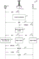
Turning now to fig. 3, a message flow 300 between a UE115-b, a first eNB105-b, and at least a second eNB 135-b is illustrated, in accordance with various aspects of the present disclosure. Each of the UE115-b, the first eNB105-b, or the second eNB 135-b may be an example of an aspect of a respective one of the UE115, the first eNB105, or the second eNB135 described with reference to fig. 1 or 2. In some cases, the first eNB105-b may comprise a master eNB and the second eNB 135-b may comprise a secondary eNB.
In the following description of the message flow 300, messages between the UE115-b, the first eNB105-b, or the second eNB 135-b may be transmitted in a different order than the exemplary order shown, or operations performed by the UE115-b, the first eNB105-b, or the second eNB 135-b may be performed in a different order or at a different time. Certain messages or operations may also be placed outside of message flow 300, or other messages or operations may be added to message flow 300.
The message flow 300 may begin with the UE115-b establishing a connection 305 with a first eNB105-b and a connection 315 with a second eNB 135-b. Each of the first eNB105-b and the second eNB 135-b may provide the UE115-b with radio resources for respective uplink communications. Each of the first eNB105-b and the second eNB 135-b may also provide the UE115-b with radio resources for respective downlink communications. At block 310, the first eNB105-b may be used to coordinate multi-connection communications of the UE115-b with the first eNB105-b and the second eNB 135-b. To assist the first eNB105-b in coordinating multi-connection communications for the UE115-b, the first eNB105-b may transmit or receive backhaul communications 320 with the second eNB 135-b. In some embodiments, the first eNB105-b and the second eNB 135-b may communicate with the UE115-b using different carriers and, thus, may send or receive backhaul communications 320 via a non-ideal backhaul link (e.g., a backhaul link implementing the X2 interface).
At block 325, the first eNB105-b may determine an allocation (e.g., a power allocation, a percentage allocation such as a percentage of uplink transmit power, etc.) of uplink transmit power for the UE115-b between the first eNB105-b and at least a second eNB 135-b. The uplink transmit power may be a maximum uplink transmit power in some cases.
When the determination is made at block 325, the first eNB105-b may send an indication 330 to the UE115-b of an allocation of uplink transmit power between the first eNB105-b and at least a second eNB 135-b. In some cases, the indication 335 may also be sent to the second eNB 135-b. The indication of the allocation of uplink transmit power 330, 335 may in some cases include an indication of a maximum uplink transmit power or a percentage of the maximum uplink transmit power allocated to each of the first eNB105-b and the at least second eNB 135-b.
In certain examples, the indication 330 of the allocation of uplink transmit power between the first eNB105-b and at least the second eNB 135-b may be based at least in part on the UL/DL configuration of the first eNB105-b or the second eNB 135-b, such as when the first eNB105-b or the second eNB 135-b is operating in a TDD mode. For example, when an eNB operates in TDD mode, the number of active uplink carriers may change over time based on the TDD configuration of each cell within the eNB. When the number of active uplink carriers used by the eNB is less during a particular time period, more of the total uplink transmit power available to the UE115-b during the time period may be allocated to another eNB with which the UE115-b may communicate during the time period. Conversely, when the number of active uplink carriers used by the eNB is greater during a particular time period, more of the total uplink transmit power available to the UE115-b during that time period may be allocated to the eNB.
In some examples, the indication 330 of the allocation of uplink transmit power between the first eNB105-b and at least the second eNB 135-b may include an indication of a subframe over which substantially all of the transmit power may be allocated to the first eNB105-b or the second eNB 135-b. For example, during a subframe or time period in which uplink communication to an eNB is not expected, substantially all of the uplink transmit power may be allocated to one or more other enbs.
In some cases, indication 330 may include a time index. The time index may be used to indicate a subframe or time period in which the eNB is allocated a specific uplink transmit power, and may be used to allocate different uplink transmit powers to different enbs within the subframe or time period. Thus, in a particular example, the indication 330 may comprise a set of values parameterized by a time index.
At block 340, and in certain variations, the UE115-b may determine an allocation of uplink transmit power between multiple cells of the first eNB105-b or the second eNB 135-b based on the indication 330 of the allocation of uplink transmit power between the first eNB105-b and at least the second eNB 135-b. The allocation of uplink transmit power between the multiple cells may be semi-statically specified in the indication 330 in some cases (e.g., the first eNB105-b may specify or configure an uplink transmit power value for each cell that may be used by the UE until the UE receives an adjusted indication from the first eNB105-b of the allocation of uplink transmit power between the first eNB105-b and at least the second eNB 135-b). The allocation of uplink transmit power between the multiple cells may be semi-statically specified in the indication by time index in other cases (e.g., the first eNB105-b may specify or configure multiple uplink transmit power values for each cell for each time index that may be used by the UE115-b until the UE115-b receives an adjusted indication from the first eNB105-b that includes an allocation of uplink transmit power between the first eNB105-b and at least the second eNB 135-b).
At block 340, the indication 330 of the allocation of uplink transmit power between the first eNB105-b and at least the second eNB 135-b may include an allocation of total transmit power between communications with the first eNB105-b and the second eNB 135-b. In these embodiments, the UE115-b may determine, at the UE115-b, an uplink transmit power for each of a plurality of cells controlled by the first eNB105-b or the second eNB 135-b based on an indication of an allocation of the uplink transmit power between the first eNB105-b and at least the second eNB 135-b. In some cases, the uplink transmit power per cell (e.g., the maximum uplink transmit power per cell) may be dynamically adjusted at the UE 115-b.
At block 345, the first eNB105-b may schedule communications (including uplink communications) between the UE115-b and the first eNB 105-b. At block 350, the second eNB 135-b may independently schedule communications (including uplink communications) between the UE115-b and the second eNB 135-b. Upon receiving the scheduling information 355 or 360, the UE115-b may transmit uplink communications 365 to the first eNB105-b and uplink communications 370 to the second eNB 135-b based on the indication 330 of the allocation of uplink transmit power for the UE115-b between the first eNB105-b and at least the second eNB 135-b.
Fig. 4 illustrates a message flow 400 between a UE115-c, a first eNB105-c, and at least a second eNB 135-c, in accordance with various aspects of the present disclosure. Each of the UE115-c, the first eNB105-c, or the second eNB 135-c may be an example of an aspect of a respective one of the UE115, the first eNB105, or the second eNB135 described with reference to fig. 1, 2, or 3. In some cases, the first eNB105-c may comprise a master eNB and the second eNB 135-c may comprise a secondary eNB.
In the following description of the message flow 400, messages between the UE115-c, the first eNB105-c, or the second eNB 135-c may be transmitted in a different order than the exemplary order shown, or operations performed by the UE115-c, the first eNB105-c, or the second eNB 135-c may be performed in a different order or at a different time. Certain messages or operations may also be put outside of message flow 400 or other messages or operations may be added to message flow 400.
The message flow 400 may begin with the UE115-c having established a connection 405 with a first eNB105-c and a connection 415 with a second eNB 135-c. Each of the first eNB105-c and the second eNB 135-c may provide the UE115-c with radio resources for respective uplink communications. Each of the first eNB105-c and the second eNB 135-c may also provide the UE115-c with radio resources for respective downlink communications. The first eNB105-c may be used at block 410 to coordinate multi-connection communications of the UE115-c with the first eNB105-c and the second eNB 135-c. To assist the first eNB105-c in coordinating multi-connection communications for the UE115-c, the first eNB105-c may transmit or receive backhaul communications 420 with the second eNB 135-c. In some embodiments, the first eNB105-c and the second eNB 135-c may communicate with the UE115-c using different carriers and, thus, may send or receive backhaul communications 420 via a non-ideal backhaul link (e.g., a backhaul link implementing the X2 interface).
When transmitting uplink communications to the first eNB105-c and the second eNB 135-c, the UE115-c may transmit the uplink communications based on an indication of an allocation of uplink transmit power for the UE115-c between the first eNB105-c and at least the second eNB 135-c. The indication may be provided to the UE115-c by the first eNB 105-c.
At block 425, the first eNB105-c may schedule communications, including uplink communications, between the UE115-c and the first eNB 105-c. At block 430, the second eNB 135-c may independently schedule communications (including uplink communications) between the UE115-c and the second eNB 135-c. Upon receiving the scheduling information 435 or 440, the UE115-c may transmit uplink communications to the first eNB105-c or the second eNB 135-c based on the current indication of the allocation of uplink transmit power for the UE115-c between the first eNB105-c and at least the second eNB 135-c.
At block 445, the UE115-c may generate a power headroom report for an eNB (e.g., the first eNB105-c or the second eNB 135-c). Triggering generation of a power headroom report for an eNB (e.g., the first eNB105-c or the second eNB 135-c) may be based on a condition of the eNB or a neighboring eNB (e.g., an eNB other than the eNB for which the power headroom report is triggered). As an example, the condition of the eNB or neighboring eNB may be a determination that the uplink transmit power of the UE115-c for the eNB or neighboring eNB has crossed a threshold. In some cases, the threshold may include a maximum uplink power of the eNB. As a further example, the condition of the eNB or the neighboring eNB may be a measured path loss of the eNB or the neighboring eNB (e.g., a path loss change that satisfies a threshold). As yet a further example, the condition of the eNB or the neighboring eNB may be a determination that the eNB or the neighboring eNB has activated an uplink cell.
The power headroom report may include power headroom information for both the first eNB105-c and the second eNB 135-c. Alternatively, the power headroom information may be for only the eNB135 that triggered the power headroom report. Including power headroom information for both the first eNB105-c and the second eNB 135-c may reduce power headroom reporting overhead and enable the enbs to estimate the total uplink transmit power used by the UE 115-c. In some examples, the power headroom information may be calculated per cell as follows:
PH (cell) ═ maximum power (cell) -actual transmission power (cell), (equation 1) where PH (cell) is the power headroom of the cell, maximum power (cell) is the maximum uplink transmission power of the cell, and actual transmission power (cell) is the current actual uplink transmission power of the cell.
In some cases, a power headroom report may be automatically sent to the eNB for which the power headroom report is triggered. In other cases, a power headroom report may be sent to the eNB for which it is triggered in response to a trigger message received from the eNB. In the latter case, and by way of example, the power headroom report 455 triggered for the first eNB105-c may be sent to the first eNB105-c in response to a trigger message (e.g., power headroom request 450) received from the first eNB 105-c.
The power headroom report may be sent to the first eNB105-c or the second eNB 135-c. In some cases, a power headroom report may be sent to the eNB for which the power headroom report is triggered (e.g., the power headroom report 455 triggered for the first eNB105-c may be sent to the first eNB105-c as indicated by the transmission of the power headroom report 455). In other cases, a power headroom report may be sent to the eNB for which the power headroom report was triggered as well as the neighboring enbs (e.g., the power headroom report 455 triggered for the first eNB105-c may be sent to the first eNB105-c and the second eNB 135-b as indicated by the transmission of the power headroom report 455 and the power headroom report 455-a). In the latter case, the UE115-c may in some cases send a power headroom report to the neighboring eNB based on determining that uplink resources are allocated to the UE115-c for uplink transmissions to the neighboring eNB. In some cases, the eNB for which the power headroom report is triggered may send (e.g., relay) the power headroom report to another eNB, as indicated by the transmission of the power headroom report 455-b from the second eNB 135-c to the first eNB 105-c. In an additional or alternative example, the first eNB105-c and the second eNB 135-b may exchange the power headroom report 135-b received from the UE115-c over a backhaul between the first eNB105-c and the second eNB 135-c.
At block 460, the first eNB105-c may adjust an allocation of uplink transmit power for the UE115-c between the first eNB105-c and the second eNB 135-c. The allocation may be adjusted based on power headroom report 455.
When the adjustment is made at block 460, the first eNB105-c may send an indication 465 to the UE115-c of the allocation of uplink transmit power between the first eNB105-c and at least the second eNB 135-c. In some cases, the indication 470 may also be transmitted to the second eNB 135-c. The indication 465, 470 of the allocation of uplink transmit power may in some cases include an indication of the maximum uplink transmit power or percentage of uplink transmit power allocated to each of the first eNB105-c and the at least second eNB 135-c.
When the first eNB105-c or the second eNB 135-c is operating in a TDD mode, the indication 465 of the allocation of uplink transmit power between the first eNB105-c and at least the second eNB 135-c may be based at least in part on the UL/DL configuration of the first eNB105-c or the second eNB 135-c. For example, when an eNB operates in TDD mode, the number of active uplink carriers may change over time based on the TDD configuration of each cell within the eNB. When the number of active uplink carriers used by the eNB is small during a particular time period, more of the total uplink transmit power available to the UE during that time period may be allocated to another eNB with which the UE may communicate during that time period. Conversely, when the number of active uplink carriers used by the eNB is greater during a particular time period, more of the total uplink transmit power available to the UE during that time period may be allocated to the eNB.
The indication 465 of the uplink transmit power between the first eNB105-c and at least the second eNB 135-c may include an indication of subframes over which substantially all transmit power may be allocated to either the first eNB105-c or the second eNB 135-c. For example, substantially all uplink transmit power may be allocated to one or more other enbs during a subframe or time period in which uplink communications to the eNB are not expected.
In some cases, indication 465 may include a time index. The time index may be used to indicate a subframe or time period in which the eNB is allocated a specific uplink transmit power, and may be used to allocate different uplink transmit powers to different enbs within the subframe or time period.
At block 475, and after receiving the indication of uplink transmit power 465, the UE115-c may determine a power headroom of the first eNB105-c and the second eNB 135-c with respect to the uplink transmit power allocated to the first eNB105-c or the second eNB 135-c in the indication of uplink transmit power 465.
Fig. 5 illustrates a message flow 500 between a UE115-d, a first eNB 105-d, and at least a second eNB135-d, in accordance with various aspects of the present disclosure. Each of the UE115-d, the first eNB 105-d, or the second eNB135-d may be an example of an aspect of a respective one of the UE115, the first eNB105, or the second eNB135 described with reference to fig. 1, 2, 3, or 4. In some cases, the first eNB 105-d may comprise a master eNB and the second eNB135-d may comprise a secondary eNB.
In the following description of the message flow 500, messages between the UE115-d, the first eNB 105-d, or the second eNB135-d may be transmitted in a different order than the illustrated exemplary order, or operations performed by the UE115-d, the first eNB 105-d, or the second eNB135-d may be performed in a different order or at a different time. Certain messages or operations may also be placed outside of message flow 500 or other messages or operations may be added to message flow 500.
The message flow 500 may begin with the UE115-d having established a connection 505 with the first eNB 105-d and a connection 515 with the second eNB 135-d. Each of the first eNB 105-d and the second eNB135-d may provide the UE115-d with radio resources for respective uplink communications. Each of the first eNB 105-d and the second eNB135-d may also provide the UE115-d with radio resources for respective downlink communications. The first eNB 105-d may be used at block 510 to coordinate multi-connection communications of the UE115-d with the first eNB 105-d and the second eNB 135-d. To assist the first eNB 105-d in coordinating multi-connection communications for the UE115-d, the first eNB 105-d may transmit or receive communications 520 with the second eNB 135-d. In some embodiments, the first eNB 105-d and the second eNB135-d may communicate with the UE115-d using different carriers and, thus, may send or receive communications 520 via a non-ideal backhaul link (e.g., a backhaul link implementing the X2 interface).
When transmitting uplink communications to the first eNB 105-d and the second eNB135-d, the UE115-d may transmit the uplink communications based on an indication of an allocation of uplink transmit power for the UE115-d between the first eNB 105-d and at least the second eNB 135-d. The indication may be provided to the UE115-d by the first eNB 105-d.
At block 525, the UE115-d may modify an allocation of uplink transmit power between the first eNB 105-d and the second eNB135-d (or an allocation of uplink transmit power between cells). In some cases, UE115-d may modify the allocation of uplink transmit power by borrowing the uplink transmit power allocated to one eNB or cell and reallocating the borrowed uplink transmit power to another eNB or cell. The modification of the allocation of uplink transmit power may in some cases be based on a priority of uplink data or control information of one of the enbs (e.g., first eNB 105-d or second eNB 135-d) with respect to other ones of the enbs. The modification may also or alternatively be based on the priority of the uplink data or control information of the cell. The modification may also or alternatively be based on the uplink not being used by the eNB or cell.
At block 530, generation of a power headroom report may be triggered based on a modification of an allocation of uplink transmit power between the first eNB 105-d and the second eNB135-d (or between cells of one or more of the first eNB 105-d and the second eNB 135-d). In some cases, the power headroom report may include an indication that the uplink transmit power of one of the first eNB 105-d or the second eNB135-d has exceeded the maximum transmit power allocated to that eNB.
The power headroom report may include power headroom information for both the first eNB 105-d and the second eNB 135-d. Including power headroom information for both the first eNB 105-d and the second eNB135-d may reduce power headroom reporting overhead and enable the enbs to estimate the total uplink transmit power used by the UE 115-e. In some examples, the power headroom information may be calculated using equation 1.
The power headroom report 535 may be sent to the first eNB 105-d or the second eNB 135-d. In some cases, a power headroom report may be sent to the eNB receiving power during the allocation of the modified uplink transmit power. Such a power headroom report may include negative power headroom information. In other cases, a power headroom report may be sent to the eNB from which power was borrowed during the allocation that modified the uplink transmit power. The latter power headroom report may subtract the borrowed power from the allocated maximum power of the eNB or cell. In case of power headroom information per cell, the power headroom information may be calculated as:
PH (cell) ═ maximum power (cell) -actual transmission power (cell) -borrowed power (cell), (equation 2)
Wherein the borrowed power (cell) is power borrowed from the cell.
At block 540, the first eNB 105-d may adjust an allocation of uplink transmit power for the UE115-d between the first eNB 105-d and the second eNB 135-d. The allocation may be adjusted based on the power headroom report 535.
When the adjustment is made at block 540, the first eNB 105-d may send an indication 545 to the UE115-d of an allocation of uplink transmit power between the first eNB 105-d and at least a second eNB 135-d. In some cases, an indication 550 may also be sent to the second eNB 135-d. The indication 545, 550 of the allocation of uplink transmit power may in some cases include an indication of a maximum uplink transmit power allocated to each of the first eNB 105-d and the at least second eNB 135-d.
In certain embodiments, the indication 545 of the uplink transmit power between the first eNB 105-d and at least the second eNB135-d may be based at least in part on the UL/DL configuration of the first eNB 105-d or the second eNB135-d, such as when the first eNB 105-d or the second eNB135-d is operating in a TDD mode. For example, when the eNB is operating in TDD mode, the number of active uplink carriers may change over time based on the TDD configuration of each cell within the eNB. When the number of active uplink carriers used by the eNB is less during a particular time period, more of the total uplink transmit power available to the UE115-d during the time period may be allocated to another eNB with which the UE115-d may communicate during the time period. Conversely, when the number of active uplink carriers used by the eNB is greater during a particular time period, more of the total uplink transmit power available to the UE115-d during that time period may be allocated to the eNB.
In certain embodiments, the indication 545 of the allocation of uplink transmit power between the first eNB 105-d and at least the second eNB135-d may include an indication of a subframe over which substantially all transmit power may be allocated to the first eNB 105-d or the second eNB 135-d. For example, substantially all uplink transmit power may be allocated to one or more other enbs during a subframe or time period in which uplink communications to the eNB are not expected.
In some cases, the indication 545 may include a time index. The time index may be used to indicate a subframe or time period during which the eNB is allocated a particular uplink transmit power, and may be used to allocate different uplink transmit powers to different enbs within the subframe or time period.
At block 555, and after receiving the indication 545 of the uplink transmit power, the UE115-d may determine a power headroom of the first eNB 105-d and the second eNB135-d with respect to the uplink transmit power allocated to the first eNB 105-d or the second eNB135-d in the indication 545 of the uplink transmit power.
Referring now to fig. 6, a block diagram 600 illustrates an example of a device 605 that may be used for wireless communication in accordance with various aspects of the disclosure. The device 605 may be an example of one or more aspects of one of the UE115, the first eNB105, or the second eNB135 described with reference to fig. 1, 2, 3, 4, or 5. The device 605 may also be a processor. The device 605 may include a receiver module 610, a wireless communication management module 620, and a transmitter module 630. Each of these components may be in communication with each other.
The components of device 605 may be implemented individually or collectively using one or more Application Specific Integrated Circuits (ASICs) adapted to perform some or all of the functions applicable in hardware. Alternatively, the functions may be performed by one or more other processing units (or cores), on one or more integrated circuits. In other embodiments, other types of integrated circuits (e.g., structured/platform ASICs, Field Programmable Gate Arrays (FPGAs), and other semi-custom ICs) may be used that may be programmed in any manner known in the art. The functions of each unit may also be implemented, in whole or in part, with instructions contained in a memory, formatted to be executed by one or more general or special purpose processors.
The receiver module 610 may include any number of receivers. In some cases, the receiver module 610 may include a cellular receiver. The cellular receiver may be an LTE/LTE-a receiver in some cases. Cellular receivers may be used to receive various types of data or control signals (collectively referred to as transmissions). The transmission may be received over one or more communication channels of a wireless communication system (e.g., wireless communication system 100 or 200 described with reference to fig. 1 or 2). In some cases, the receiver module 610 may include an alternative or additional type of receiver, such as an ethernet or WLAN receiver. An ethernet or WLAN receiver may also be used to receive various types of data or control signals and may also receive transmissions over one or more communication channels of a wireless communication system (e.g., wireless communication systems 100 or 200).
The transmitter module 630 may include any number of transmitters. In some cases, transmitter module 630 may include a cellular transmitter. The cellular transmitter may be an LTE/LTE-a transmitter in some cases. Cellular transmitters may be used to transmit various types of data or control signals (collectively referred to as transmissions). The transmission may be sent over one or more communication channels of a wireless communication system (e.g., wireless communication systems 100 or 200). In some cases, the transmitter 630 may include an alternative or additional type of transmitter (e.g., an ethernet or WLAN transmitter). An ethernet or WLAN transmitter may also be used to transmit various types of data or control signals and may also transmit over one or more communication channels of a wireless communication system (e.g., wireless communication systems 100 or 200).
The wireless communication management module 620 may perform various functions. In embodiments of the device 605 in which the device 605 may be configured as a UE115, the wireless communication management module 620 may be used to manage multi-connection communications with the first eNB105 and at least the second eNB 135. The wireless communication management module 620 may also be used to manage the allocation of uplink transmit power between the first eNB105 and at least the second eNB 135.
In embodiments of the device 605 in which the device 605 may be configured as a first eNB105, the wireless communication management module 620 may be used to manage multi-connection communications for a UE115 in communication with the device 605 and at least a second eNB 135. The wireless communication management module 620 can also be configured to allocate uplink transmit power between the device 605 and at least a second eNB 135.
In embodiments of the device 605 in which the device 605 may be configured as a second eNB135, the wireless communication management module 620 may be used to manage multi-connection communications for a UE115 communicating with the first eNB105, the device 605, and possibly one or more other second enbs 135. The wireless communication management module 620 may also be used to facilitate allocation of uplink transmit power between the first eNB105, the device 605, and possibly one or more other second enbs 135.
Referring now to fig. 7, a block diagram 700 illustrates an example of a device 605-a that may be used for wireless communication in accordance with various aspects of the disclosure. The device 605-a may be an example of one or more aspects of one of the UE115 or the device 605 configured as a UE as described with reference to fig. 1, 2, 3, 4, 5, or 6. The device 605-a may also be a processor. The device 605-a may include a receiver module 610, a wireless communication management module 620-a, or a transmitter module 630. Each of these components may be in communication with each other.
The components of device 605-a may be implemented individually or collectively with one or more ASICs adapted to perform some or all of the functions applicable in hardware. Alternatively, the functions may be performed by one or more other processing units (or cores), on one or more integrated circuits. In other embodiments, other types of integrated circuits (e.g., structured/platform ASICs, FPGAs, and other semi-custom ICs) may be used that may be programmed in any manner known in the art. The functions of each unit may also be implemented, in whole or in part, with instructions contained in a memory, formatted to be executed by one or more general or special purpose processors.
The receiver module 610 may be configured similar to the receiver module 610 described with reference to fig. 6. Similarly, the transmitter module 630 may be configured similar to the transmitter module 630 described with reference to fig. 6.
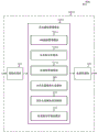
The wireless communication management module 620-a may be an example of the wireless communication management module 620 described with reference to fig. 6, and may include an eNB connection management module 705, an uplink transmit power management module 710, and an uplink communication management module 715.
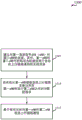
The eNB connection management module 705 may be used to establish a connection with a first eNB and a second eNB. Each of the first eNB and the second eNB may provide radio resources for the UE for respective uplink communications. Each of the first eNB and the second eNB may also provide the UE115-b with radio resources for respective downlink communications. In certain instances, the first eNB may be an example of one or more aspects of one of the first eNB105 or the device 605 configured as the first eNB as described with reference to fig. 1, 2, 3, 4, 5, or 6. In certain instances, the second eNB may be an example of one or more aspects of one of the second enbs 135 or the device 605 configured as a second eNB as described with reference to fig. 1, 2, 3, 4, 5, or 6. In some cases, the first eNB may comprise a master eNB and the second eNB may comprise a secondary eNB.
The uplink transmit power management module 710 may be for receiving, at the device 605-a from the first eNB, an indication including an allocation of uplink transmit power between the first eNB and at least a second eNB. The uplink transmit power may be a maximum uplink transmit power in some cases.
The indication including the allocation of uplink transmit power between the first eNB and at least the second eNB may be based at least in part on a UL/DL configuration of the first eNB or the second eNB when the first eNB or the second eNB operates in a TDD mode. For example, when an eNB operates in TDD mode, the number of active uplink carriers may change over time based on the TDD configuration of each cell within the eNB. When the number of active uplink carriers used by the eNB is small during a particular time period, more of the total uplink transmit power available to the UE during the time period may be allocated to another eNB with which the UE may communicate during the time period. Conversely, when the number of active uplink carriers used by the eNB is greater during a particular time period, more of the total uplink transmit power available to the UE during that time period may be allocated to the eNB.
In some examples, the indication including the allocation of uplink transmit power between the first eNB and at least the second eNB may include an indication of a subframe over which substantially all transmit power may be allocated to the first eNB or the second eNB. For example, substantially all uplink transmit power may be allocated to one or more other enbs during a subframe or time period in which uplink communications to the eNB are not expected.
In some cases, the indication may include a time index. The time index may be used to indicate a subframe or time period during which the eNB is allocated a particular uplink transmit power, and may be used to allocate different uplink transmit powers to different enbs within the subframe or time period.
In some examples, uplink transmit power management module 710 may determine an allocation of uplink transmit power between a plurality of cells of the first eNB or the second eNB based on an indication including the allocation of uplink transmit power between the first eNB and at least the second eNB. The allocation of uplink transmit power between multiple cells may be semi-statically specified in the indication in some cases (e.g., the first eNB may specify or configure an uplink transmit power value for each cell that may be used by the UE until the UE receives an adjusted indication from the first eNB that includes the allocation of uplink transmit power between the first eNB and at least a second eNB). The allocation of uplink transmit power between the multiple cells may otherwise be semi-statically specified in the indication by time index (e.g., the first eNB may specify or configure multiple uplink transmit power values for each cell for each time index that may be used by the UE until the UE receives an adjusted indication from the first eNB that includes an allocation of uplink transmit power between the first eNB and at least a second eNB).
In some examples, the indication including the allocation of uplink transmit power between the first eNB and at least the second eNB may include an allocation of a total transmit power or a percentage of transmit power between communications with the first eNB and the second eNB. In these embodiments, uplink transmit power management module 710 may determine an uplink transmit power for each of a plurality of cells controlled by the first eNB or the second eNB based on an indication including an allocation of the uplink transmit power between the first eNB and at least the second eNB. In some cases, the uplink transmit power per cell (e.g., the maximum uplink transmit power per cell) may be dynamically adjusted by uplink transmit power management module 710.
The uplink communication management module 715 may be used to send uplink communications from the device 605-a to the first eNB and the second eNB based on the indication including the allocation of uplink transmit power between the first eNB and at least the second eNB.
Referring now to fig. 8, a block diagram 800 illustrates an example of a device 605-b that may be used for wireless communication in accordance with various aspects of the disclosure. The device 605-b may be an example of one or more aspects of one of the UE115 or the device 605 configured as a UE as described with reference to fig. 1, 2, 3, 4, 5, 6, or 7. The device 605-b may also be a processor. The device 605-b may include a receiver module 610, a wireless communication management module 620-b, and a transmitter module 630. Each of these components may be in communication with each other.
The components of device 605-b may be implemented individually or collectively with one or more ASICs adapted to perform some or all of the functions applicable in hardware. Alternatively, the functions may be performed by one or more other processing units (or cores), on one or more integrated circuits. In other embodiments, other types of integrated circuits (e.g., structured/platform ASICs, FPGAs, and other semi-custom ICs) may be used that may be programmed in any manner known in the art. The functions of each unit may also be implemented, in whole or in part, with instructions contained in a memory, formatted to be executed by one or more general or special purpose processors.
The receiver module 610 may be configured similar to the receiver module 610 described with reference to fig. 6. Similarly, the transmitter module 630 may be configured similar to the transmitter module 630 described with reference to fig. 6.
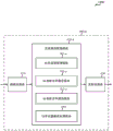
The wireless communication management module 620-b may be an example of the wireless communication management module 620 described with reference to fig. 6 or 7, and may include an eNB connection management module 705-a, an uplink transmit power management module 710-a, an uplink communication management module 715-a, a power headroom report generation module 805, a power headroom report transmission module 810, and an uplink transmit power modification module 815.
The eNB connection management module 705-a may be used to establish a connection with a first eNB and a second eNB. Each of the first eNB and the second eNB may provide radio resources for the UE for respective uplink communications. Each of the first eNB and the second eNB may also provide the UE115-b with radio resources for respective downlink communications. In certain instances, the first eNB may be an example of one or more aspects of one of the first eNB105 or the device 605 configured as the first eNB as described with reference to fig. 1, 2, 3, 4, 5, or 6. In certain instances, the second eNB may be an example of one or more aspects of one of the second enbs 135 or the device 605 configured as a second eNB as described with reference to fig. 1, 2, 3, 4, 5, or 6. In some cases, the first eNB may comprise a master eNB and the second eNB may comprise a secondary eNB.
The uplink transmit power management module 710-a may be used to receive, at the device 605-b, an indication from a first eNB including an allocation of uplink transmit power between the first eNB and at least a second eNB. The uplink transmit power may be a maximum uplink transmit power in some cases.
In certain embodiments, the indication comprising the allocation of uplink transmit power between the first eNB and at least the second eNB may be based at least in part on a UL/DL configuration of the first eNB or the second eNB, e.g., when the first eNB or the second eNB is operating in a TDD mode. For example, when an eNB operates in TDD mode, the number of active uplink carriers may change over time based on the TDD configuration of each cell within the eNB. When the number of active uplink carriers used by the eNB is small during a particular time period, more of the total uplink transmit power available to the UE during the time period may be allocated to another eNB with which the UE may communicate during the time period. Conversely, when the number of active uplink carriers used by the eNB is greater during a particular time period, more of the total uplink transmit power available to the UE during that time period may be allocated to the eNB.
In some examples, the indication including the allocation of uplink transmit power between the first eNB and at least the second eNB may include an indication of a subframe over which substantially all transmit power may be allocated to the first eNB or the second eNB. For example, substantially all uplink transmit power may be allocated to one or more other enbs during a subframe or time period in which uplink communications to the eNB are not expected.
In some cases, the indication may include a time index. The time index may be used to indicate a subframe or time period during which the eNB is allocated a particular uplink transmit power, and may be used to allocate different uplink transmit powers to different enbs within the subframe or time period.
In certain embodiments, the uplink transmit power management module 710-a may determine an allocation of uplink transmit power between a plurality of cells of the first eNB or the second eNB based on an indication including the allocation of uplink transmit power between the first eNB and at least the second eNB. The allocation of uplink transmit power between multiple cells may in some cases be semi-statically specified in the indication (e.g., the first eNB may specify or configure an uplink transmit power value for each cell that may be used by the UE until the UE receives an adjusted indication from the first eNB that includes the allocation of uplink transmit power between the first eNB and at least a second eNB). The allocation of uplink transmit power between the multiple cells may otherwise be semi-statically specified in the indication by time index (e.g., the first eNB may specify or configure multiple uplink transmit power values for each cell for each time index that may be used by the UE until the UE receives an adjusted indication from the first eNB that includes an allocation of uplink transmit power between the first eNB and at least a second eNB).
In some embodiments, the indication comprising the allocation of uplink transmit power between the first eNB and at least the second eNB may comprise an allocation of total transmit power or a percentage of total transmit power between communications with the first eNB and the second eNB. In these embodiments, the uplink transmit power management module 710-a may determine the uplink transmit power of each of the plurality of cells controlled by the first eNB or the second eNB based on the indication including the allocation of the uplink transmit power between the first eNB and at least the second eNB. In some cases, the uplink transmit power per cell (e.g., the maximum uplink transmit power per cell) may be dynamically adjusted by uplink transmit power management module 710-a.
The uplink communication management module 715-a may be used to send uplink communications from the device 605-b to the first eNB and the second eNB based on the indication including the allocation of uplink transmit power between the first eNB and at least the second eNB.
The power headroom report generation module 805 may be used to trigger a power headroom report at the device 605-b. In certain embodiments, the power headroom report generation module 805 may trigger power headroom reporting by an eNB (e.g., a first eNB or a second eNB) based on a condition of the eNB or a neighboring eNB (e.g., an eNB other than the eNB for which the power headroom report is triggered). As an example, the condition of the eNB or the neighboring eNB may be a determination that the uplink transmit power of the device 605-b for the eNB or the neighboring eNB has crossed a threshold. In some cases, the threshold may include a maximum uplink power for the eNB. As a further example, the condition of the eNB or the neighboring eNB may be a measured path loss of the eNB or the neighboring eNB (e.g., a path loss change that satisfies a threshold). As yet a further example, the condition of the eNB or the neighboring eNB may be a determination that the eNB or the neighboring eNB has activated an uplink cell.
The power headroom report generation module 805 may also be used to generate a power headroom report at the device 605-b. The power headroom report may include power headroom information for both the first eNB and the second eNB. Including power headroom information for both the first eNB and the second eNB may reduce power headroom reporting overhead and enable the eNB to estimate the total uplink transmit power used by the device 605-b. In some examples, the power headroom information may be calculated using equation 1.
The power headroom report transmission module 810 may be used to transmit a power headroom report to the first eNB or the second eNB. In some embodiments, the power headroom report may be automatically sent to the eNB for which the power headroom report is triggered. In other embodiments, the power headroom report may be sent to the eNB for which the power headroom report is triggered in response to a trigger message received from the eNB. In the latter embodiment, and by way of example, the triggered power headroom report for the first eNB may be sent to the first eNB in response to a trigger message received from the first eNB.
In some cases, the power headroom report transmission module 810 may send the power headroom report to the eNB for which the power headroom report was triggered (e.g., the power headroom report triggered for the first eNB may be sent to the first eNB). In other cases, the power headroom report transmission module 810 can transmit the power headroom report to the eNB for which the power headroom report was triggered as well as to neighboring enbs (e.g., the power headroom report triggered for a first eNB can be transmitted to the first eNB and a second eNB). In the latter case, the power headroom report transmission module 810 can send the power headroom report to the neighboring eNB based on a determination that uplink resources are allocated to the UE for uplink transmission to the neighboring eNB in some cases.
After the power headroom report transmission module 810 sends the power headroom report to the eNB, the uplink transmit power management module 710-a may be configured to receive a second indication from the first eNB including an allocation of uplink transmit power. The second indication including the allocation of uplink transmit power may change the uplink transmit power allocated to the first eNB or the second eNB. After receiving the second indication comprising the allocation of uplink transmit power, the power headroom report generation module 805 may be used to determine the power headroom of the first eNB and the second eNB with respect to the uplink transmit power allocated to the first eNB or the second eNB in the second indication.
The uplink transmit power modification module 815 may be used to modify the allocation of the total uplink transmit power between the first eNB and the second eNB (or the allocation of the uplink transmit power between cells) when it is possible and useful to send uplink communications from the UE to the first eNB or the second eNB. In some cases, the uplink transmit power modification module 815 may modify the allocation of uplink transmit power by borrowing uplink transmit power allocated to one eNB or cell and reallocating the borrowed uplink transmit power to another eNB or cell. The modification of the allocation of uplink transmit power may in some cases be based on uplink data or control information of one of the enbs (e.g., the first eNB or the second eNB) with respect to other ones of the enbs priorities. The modification may also or alternatively be based on the priority of the uplink data or control information of the cell. The modification may also or alternatively be based on the uplink not being used by the eNB or cell.
Following the modification of the allocation of uplink transmit power between the first eNB and the second eNB, a power headroom report may be generated using power headroom report generation module 805. The power headroom report may include power headroom information for both the first eNB and the second eNB. Including power headroom information for both the first eNB and the second eNB may reduce power headroom reporting overhead and enable the eNB to estimate the total uplink transmit power used by the device 605-b. In some examples, the power headroom information may be calculated using equation 1.
A power headroom report triggered by a modification of an allocation of uplink transmit power between a first eNB and a second eNB may be sent to the first eNB or the second eNB. In some cases, power headroom report transmission module 810 can send a power headroom report to an eNB that receives power during the allocation of modified uplink transmit power. Such a power headroom report may include negative power headroom information. In other cases, power headroom report transmission module 810 can send a power headroom report to the eNB from which power was borrowed during the allocation that modified the uplink transmit power. The latter power headroom report may subtract the borrowed power from the configured maximum power of the eNB or cell. In case of power headroom information by cell, the power headroom information can be calculated using equation 2.
Referring now to fig. 9, a block diagram 900 illustrates an example of a device 605-c that may be used for wireless communication in accordance with various aspects of the disclosure. The device 605-c may be an example of one or more aspects of one of the first eNB105 or the device 605 configured as a first eNB as described with reference to fig. 1, 2, 3, 4, 5, or 6. The device 605-c may also be a processor. The device 605-c may include a receiver module 610, a wireless communication management module 620-c, and a transmitter module 630. Each of these components may be in communication with each other.
The components of the devices 605-c may be implemented individually or collectively with one or more ASICs adapted to perform some or all of the functions applicable in hardware. Alternatively, the functions may be performed by one or more other processing units (or cores), on one or more integrated circuits. In other embodiments, other types of integrated circuits (e.g., structured/platform ASICs, FPGAs, and other semi-custom ICs) may be used that may be programmed in any manner known in the art. The functions of each unit may also be implemented, in whole or in part, with instructions contained in a memory, formatted to be executed by one or more general or special purpose processors.
The receiver module 610 may be configured similar to the receiver module 610 described with reference to fig. 6. Similarly, the transmitter module 630 may be configured similar to the transmitter module 630 described with reference to fig. 6.
The wireless communication management module 620-c may be an example of the wireless communication management module 620 described with reference to fig. 6, and may include a UE multi-connection management module 905, an uplink transmit power determination module 910, and an uplink transmit power communication module 915.
The UE multi-connection management module 905 may be used to coordinate multi-connection communications with at least the device 605-c and a second eNB for the UE. In certain instances, the UE may be an example of one or more aspects of one of the UE115 or the device 605 configured as a UE as described with reference to fig. 1, 2, 3, 4, 5, 6, 7, or 8. In certain instances, the second eNB may be an example of one or more aspects of one of the second enbs 135 or the device 605 configured as a second eNB as described with reference to fig. 1, 2, 3, 4, 5, or 6. In some cases, the device 605-c may comprise a primary eNB and the second eNB may comprise a secondary eNB.
The uplink transmit power determination module 910 may be configured to determine an allocation of uplink transmit power for the UE between the device 605-c and at least a second eNB. The uplink transmit power may be a maximum uplink transmit power in some cases.
In some examples, the uplink transmit power determination module 910 may determine an allocation of uplink transmit power between a plurality of cells of the device 605-c based on an indication including the allocation of uplink transmit power between the device 605-c and at least a second eNB. The allocation of uplink transmit power between the multiple cells may in some cases be semi-statically specified in the indication (e.g., the device 605-c may specify or configure an uplink transmit power value for each cell that may be used by the UE until the UE receives an adjusted indication from the device 605-c that includes the allocation of uplink transmit power between the device 605-c and at least a second eNB). The allocation of uplink transmit power between the multiple cells may otherwise be semi-statically specified in the indication by time index (e.g., the device 605-c may specify or configure multiple uplink transmit power values for each cell for each time index that may be used by the UE until the UE receives an adjusted indication from the device 605-c that includes an allocation of uplink transmit power between the device 605-c and at least a second eNB).
Uplink transmit power communication module 915 may be used to send an indication to the UE including an allocation of an uplink transmit power allocation.
In certain examples, the indication including the allocation of uplink transmit power between the device 605-c and at least the second eNB may be based at least in part on the UL/DL configuration of the device 605-c or the second eNB, such as when the device 605-c or the second eNB is operating in a TDD mode. For example, when an eNB operates in TDD mode, the number of active uplink carriers may change over time based on the TDD configuration of each cell within the eNB. When the number of active uplink carriers used by the eNB is smaller during a particular time period, more of the total uplink transmit power available to the UE during that time period may be allocated to another eNB with which the UE may communicate during that time period. Conversely, when the number of active uplink carriers used by the eNB is greater during a particular time period, more of the total uplink transmit power available to the UE during that time period may be allocated to the eNB.
In some embodiments, the indication comprising the allocation of uplink transmit power between the device 605-c and at least the second eNB may comprise an indication of a subframe over which substantially all transmit power may be allocated to the device 605-c or the second eNB. For example, substantially all uplink transmit power may be allocated to one or more other enbs during a subframe or time period in which uplink communications to the eNB are not expected.
In some cases, the indication may include a time index. The time index may be used to indicate a subframe or time period during which the eNB is allocated a particular uplink transmit power, and may be used to allocate different uplink transmit powers to different enbs within the subframe or time period.
Referring now to fig. 10, a block diagram 1000 illustrates an example of a device 605-d that may be used for wireless communication in accordance with various aspects of the disclosure. The device 605-d may be an example of one or more aspects of one of the first eNB105 or the device 605 configured as a first eNB as described with reference to fig. 1, 2, 3, 4, 5, or 6. The device 605-d may also be a processor. The device 605-d may include a receiver module 610, a wireless communication management module 620-d, and a transmitter module 630. Each of these components may be in communication with each other.
The components of the devices 605-d may be implemented individually or collectively with one or more ASICs adapted to perform some or all of the functions applicable in hardware. Alternatively, the functions may be performed by one or more other processing units (or cores), on one or more integrated circuits. In other embodiments, other types of integrated circuits (e.g., structured/platform ASICs, FPGAs, and other semi-custom ICs) may be used that may be programmed in any manner known in the art. The functions of each unit may also be implemented, in whole or in part, with instructions contained in a memory, formatted to be executed by one or more general or special purpose processors.
The receiver module 610 may be configured similar to the receiver module 610 described with reference to fig. 6. Similarly, the transmitter module 630 may be configured similar to the transmitter module 630 described with reference to fig. 6.
The wireless communication management module 620-d may be an example of the wireless communication management module 620 described with reference to fig. 6 and may include a UE multi-connection management module 905-a, an uplink transmit power determination module 910-a, an uplink transmit power communication module 915-a, and a power headroom report processing module 1005.
The UE multi-connection management module 905-a may be used to coordinate multi-connection communications with at least the device 605-d and a second eNB for the UE. In certain instances, the UE may be an example of one or more aspects of one of the UE115 or the device 605 configured as a UE as described with reference to fig. 1, 2, 3, 4, 5, 6, 7, or 8. In certain instances, the second eNB may be an example of one or more aspects of one of the second enbs 135 or the device 605 configured as a second eNB as described with reference to fig. 1, 2, 3, 4, 5, or 6. In some cases, the device 605-d may comprise a primary eNB and the second eNB may comprise a secondary eNB.
The uplink transmit power determination module 910-a may be configured to determine an allocation of uplink transmit power for the UE between the device 605-d and at least a second eNB. The uplink transmit power may be a maximum uplink transmit power in some cases.
In some examples, the uplink transmit power determination module 910-a may determine an allocation of uplink transmit power between a plurality of cells of the device 605-d based on an indication including the allocation of uplink transmit power between the device 605-d and at least a second eNB. The allocation of uplink transmit power between the multiple cells may in some cases be semi-statically specified in the indication (e.g., the device 605-d may specify or configure an uplink transmit power value for each cell that may be used by the UE until the UE receives an adjusted indication from the device 605-d that includes the allocation of uplink transmit power between the device 605-d and at least a second eNB). The allocation of uplink transmit power between the multiple cells may otherwise be semi-statically specified in the indication by time index (e.g., the device 605-d may specify or configure multiple uplink transmit power values for each cell for each time index that may be used by the UE until the UE receives an adjusted indication from the device 605-d that includes an allocation of uplink transmit power between the device 605-d and at least a second eNB).
The uplink transmit power communication module 915-a may be configured to send an indication to the UE including an allocation of an uplink transmit power allocation.
In certain examples, the indication including the allocation of uplink transmit power between the device 605-d and at least the second eNB may be based at least in part on the UL/DL configuration of the device 605-d or the second eNB, such as when the device 605-d or the second eNB is operating in a TDD mode. For example, when an eNB operates in TDD mode, the number of active uplink carriers may change over time based on the TDD configuration of each cell within the eNB. When the number of active uplink carriers used by the eNB is smaller during a particular time period, more of the total uplink transmit power available to the UE during that time period may be allocated to another eNB with which the UE may communicate during that time period. Conversely, when the number of active uplink carriers used by the eNB is greater during a particular time period, more of the total uplink transmit power available to the UE during that time period may be allocated to the eNB.
In some embodiments, the indication comprising the allocation of uplink transmit power between the device 605-d and at least the second eNB may comprise an indication of a subframe over which substantially all transmit power may be allocated to the device 605-d or the second eNB. For example, substantially all uplink transmit power may be allocated to one or more other enbs during a subframe or time period in which uplink communications to the eNB are not expected.
In some cases, the indication may include a time index. The time index may be used to indicate a subframe or time period during which the eNB is allocated a particular uplink transmit power, and may be used to allocate different uplink transmit powers to different enbs within the subframe or time period.
The power headroom report processing module 1005 may be configured to receive a power headroom report including power headroom information for at least the device 605-d and the second eNB. In some cases, as described with reference to power headroom report generation module 805 described with reference to fig. 8, the power headroom report may be received in response to at least one of: an uplink transmit power of the UE for the second eNB; a measured change in path loss for the second eNB; or the second eNB activates the uplink cell. In some cases, the power headroom report may be received in response to the device 605-d sending a trigger message (e.g., a request for a power headroom report) to the UE.
Power headroom report processing module 1005 may optionally send a power headroom report to the second eNB.
In certain embodiments, the power headroom report may indicate that the UE has modified the allocation of uplink transmit power between the device 605-d and the second eNB, and the power headroom report processing module 1005 may be operable to determine, based on the power headroom report, that the UE has modified the allocation of uplink transmit power between the device 605-d and the second eNB. In other embodiments, the power headroom report may not indicate that the UE has modified the allocation of uplink transmit power between the device 605-d and the second eNB.
In some cases, the UL transmit power determination module 910-a may be configured to adjust allocation of uplink transmit power for the UE between the device 605-d and the second eNB based on the power headroom report. In some cases, the adjustment may be based on a modification by the UE of the allocation of uplink transmit power between the first eNB and the second eNB. In some cases, UL transmit power communication module 915-a may be used to transmit the adjusted allocation of uplink transmit power to at least one of the UE or the second eNB.
In certain embodiments of the device 605-d, adjustments to the allocation of uplink transmit power for the UE between the device 605-d and the second eNB may also or alternatively be made based on messages received at the device 605-d from the second eNB. The message may include a power headroom report of the UE or information generated by the second eNB.
In certain embodiments of the device 605-d, the wireless communication management module 620-d may schedule communications (e.g., downlink or uplink communications) with the UE. Communications between the UE and the device 605-d may be scheduled independently of communications between the UE and the second eNB.
Fig. 11 illustrates a block diagram 1100 of a UE 115-e configured for wireless communication in accordance with various aspects of the disclosure. The UE 115-e may have various configurations and may be included or part of: personal computers (e.g., laptop computers, notebook computers, tablet computers, etc.), cellular telephones, PDAs, digital video cameras (DVRs), internet appliances, game consoles, e-readers, and the like. The UE 115-e may have an internal power source (not shown) for facilitating mobile operation, such as a small battery, in some cases. In certain embodiments, the UE 115-e may be an example of one or more aspects of one of the UE115 or the device 605 configured as a UE as described with reference to fig. 1, 2, 3, 4, 5, 6, 7, or 8. The UE 115-e may be configured to implement at least some of the UE features and functions described with reference to fig. 1, 2, 3, 4, 5, 6, 7, or 8. The UE 115-e may be configured to communicate with one of the first eNB105 or the device 605 configured as a first eNB, or with one or more of the second eNB135 or the device 605 configured as a second eNB, described with reference to fig. 1, 2, 3, 4, 5, 6, 9, or 10.
The UE 115-e may include a processor module 1110, a memory 1120, at least one transceiver module (represented by transceiver module 1130), at least one antenna (represented by antenna 1140), and a wireless communication management module 620-e. Each of these components may communicate with each other, directly or indirectly, over one or more buses 1135.
The memory 1120 may include a Random Access Memory (RAM) or a Read Only Memory (ROM). The memory 1120 may store computer-readable, computer-executable code 1125 containing instructions configured to, when executed, cause the processor module 1110 to perform various functions for managing wireless communications described herein. Alternatively, the code 1125 may not be directly executable by the processor module 1110, but be configured to cause the UE 115-e (e.g., when compiled and executed) to implement various of the UE features and functions described herein.
The processor module 1110 may include intelligent hardware devices such as a CPU, microcontroller, ASIC, and the like. The processor module 1110 may process information received by the transceiver module 1130 or information to be sent to the transceiver module 1130 for transmission via the antenna 1140. The processor module 1110 may also handle various aspects of managing uplink transmit power for communications with the first eNB and the second eNB, either alone or in conjunction with the wireless communication management module 620-e.
The transceiver module 1130 may include a modem configured to modulate packets and provide the modulated packets to the antenna 1140 for transmission, and to demodulate packets received from the antenna 1140. The transceiver module 1130 may in some cases be implemented as one or more transmitter modules and one or more separate receiver modules. The transceiver module 1130 may be configured to communicate bi-directionally with one or more enbs 105 or 135 or other UEs 115 via the antenna 1140. Although the UE 115-e may include a single antenna, embodiments may exist in which the UE 115-e may include multiple antennas 1140.
The wireless communication management module 620-e may be an example of one or more aspects of the wireless communication management module 620 described with reference to fig. 6, 7, or 8, and may be configured to perform or control some or all of the wireless communication management functions described with reference to fig. 3, 4, 5, 6, 7, or 8.
According to the architecture of fig. 11, the UE 115-e may also include a status module 1150. The status module 1150 may reflect and control the current device status (e.g., context, authentication, base station association, or other connection issues).
By way of example, each of the wireless communication management modules 620-e or the status module 1150, or portions of one or both modules, may be a component of the UE 115-e that communicates with some or all of the other components of the UE 115-e via one or more buses 1135. Alternatively, a processor may be used to implement the functionality of the wireless communication management module 620-e or the status module 1150, or some or all of the functionality of the wireless communication management module 620-e or the status module 1150 may be implemented by the code 1125 or the processor module 1110 or in conjunction with the processor module 1110.
The components of the UE 115-e may be implemented individually or collectively using one or more ASICs adapted to perform some or all of the functions applicable in hardware. Alternatively, the functions may be performed by one or more other processing units (or cores), on one or more integrated circuits. In other embodiments, other types of integrated circuits (e.g., structured/platform ASICs, FPGAs, and other semi-custom ICs) may be used that may be programmed in any manner known in the art. The functions of each unit may also be implemented, in whole or in part, with instructions contained in a memory, formatted to be executed by one or more general or special purpose processors. Each of the indicated modules may be a unit for performing one or more functions related to the operation of the UE 115-e.
Fig. 12 shows a block diagram 1200 illustrating an eNB105-e configured for wireless communication in accordance with various aspects of the disclosure. In certain embodiments, the enbs 105-e may be examples of one or more aspects of one of the first eNB105 or the device 605 configured as a first eNB, or one of the second enbs 135, as described with reference to fig. 1, 2, 3, 4, 5, 6, 9, or 10. The enbs 105-e may be configured to implement at least some of the first or second eNB features and functions described with reference to fig. 1, 2, 3, 4, 5, 6, 9 or 10. The eNB105-e may be configured to communicate with one or more of the UE115 or the device 605 configured as a UE as described with reference to fig. 1, 2, 3, 4, 5, 6, 7, or 8. The enbs 105-e may also be configured to communicate with the first eNB or the second eNB135 as described with reference to fig. 2, 3, 4, 5, 6, 7, 8, 9, 10, or 11.
The eNB105-e may include a processor module 1210, a memory 1220, at least one transceiver module (represented by transceiver module 1230), at least one antenna (represented by antenna 1240), and a wireless communication management module 620-f. The enbs 105-e may also include one or more of an eNB communication module 1250 and a network communication module 1260. Each of these components may communicate with each other, directly or indirectly, over one or more buses 1235.
The memory 1220 may include a RAM or a ROM. The memory 1220 may store computer-readable, computer-executable code 1225 containing instructions configured to, when executed, cause the processor module 1210 to perform various functions for managing wireless communications described herein. Alternatively, the code 1225 may not be directly executable by the processor module 1210, but rather configured to cause the eNB105-e (e.g., when compiled and executed) to perform various ones of the eNB features and functions described herein.
The processor module 1210 may include intelligent hardware devices such as a CPU, microcontroller, ASIC, etc. The processor module 1210 may process information received through the transceiver module 1230, the eNB communication module 1250, or the network communication module 1260. Processor module 1210 may also process information to be sent to transceiver module 1230 for transmission through antennas 1240, to be sent to eNB communications module 1250 for transmission to one or more other enbs 105-f and 105-g, or to network communications module 1260 for transmission to core network 130-a, which may be an example of one or more aspects of core network 130 described with reference to fig. 1. The processor module 1210 may handle various aspects of managing uplink transmit power for one or more UEs in communication with the eNB105-e and at least one other eNB, either alone or in conjunction with the wireless communication management module 620-f.
The transceiver module 1230 may include a modem configured to modulate packets and provide the modulated packets to the antennas 1240 for transmission, and to demodulate packets received from the antennas 1240. The transceiver module 1230 may in some cases be implemented as one or more transmitter modules and one or more separate receiver modules. The transceiver module 1240 may be configured to communicate bi-directionally with one or more UEs 115 via the antennas 1240. The eNB105-e may generally include multiple antennas 1240 (e.g., an antenna array). The eNB105-e may communicate with the core network 130-a through a network communication module 1260. The eNB105-e may also communicate with other eNBs (e.g., eNBs 105-f and 105-g) using the eNB communication module 1250.
The wireless communication management module 620-f may be an example of one or more aspects of the wireless communication management module 620 described with reference to fig. 6, 9, or 10, and may be configured to perform or control some or all of the wireless communication management functions described with reference to fig. 3, 4, 5, 6, 9, or 10. By way of example, the wireless communication management module 620-f, or portions thereof, may be a component of the eNB105-e in communication with some or all of the other components of the eNB105-e via one or more buses 1235. Alternatively, the functionality of the wireless communication management module 620-f may be implemented using a processor, or some or all of the functionality of the wireless communication management module 620-f may be implemented by the code 1225 or the processor module 1210, or in combination with the processor module 1210.
The components of the eNB105-e may be implemented individually or collectively using one or more ASICs adapted to perform some or all of the functions applicable in hardware. Alternatively, the functions may be performed by one or more other processing units (or cores), on one or more integrated circuits. In other embodiments, other types of integrated circuits (e.g., structured/platform ASICs, FPGAs, and other semi-custom ICs) may be used that may be programmed in any manner known in the art. The functions of each unit may also be implemented, in whole or in part, with instructions contained in a memory, formatted to be executed by one or more general or special purpose processors. Each of the indicated modules may be a unit for performing one or more functions related to the operation of the eNB 105-e. In some cases the components of an ENB105-e may be duplicated or distributed among more than one base station.
Fig. 13 is a flow diagram illustrating a method 1300 of wireless communication by a UE in accordance with various aspects of the present disclosure. For clarity, the method 1300 is described below with reference to an aspect of one of the UE115 or the device 605 configured as a UE as described with reference to fig. 1, 2, 3, 4, 5, 6, 7, 8, or 1, an aspect of one of the first eNB105 or the device 605 configured as a first eNB as described with reference to fig. 1, 2, 3, 4, 5, 6, 9, 10, or 12, or an aspect of one of the second eNB135 or the device 605 configured as a second eNB as described with reference to fig. 1, 2, 3, 4, 5, 6, or 12. In one implementation, the wireless communication management module 620 described with reference to fig. 6, 7, 8, or 11 may execute one or more sets of codes for controlling the functional elements of the UE115 or the device 605 configured as a UE to perform the functions described below.
At block 1305, a connection may be established with a first eNB and a second eNB, where each of the first eNB and the second eNB may provide radio resources for a UE for respective uplink communications. Each of the first eNB and the second eNB may also provide the UE115-b with radio resources for respective downlink communications. In some cases, the first eNB may comprise a master eNB and the second eNB may comprise a secondary eNB. The operations at block 1305 may be performed or managed using the wireless communication management module 620 described with reference to fig. 6, 7, 8, or 11 or the eNB connection management module 705 described with reference to fig. 7 or 8.
At block 1310, an indication of an allocation of uplink transmit power between a first eNB and at least a second eNB may be received from the first eNB. The indication of the allocation of uplink transmit power may in some cases include an indication of a maximum uplink transmit power allocated to each of the first eNB and the at least a second eNB. The operations at block 1310 may be performed or managed using the wireless communication management module 620 described with reference to fig. 6, 7, 8, or 11 or the uplink transmit power management module 710 described with reference to fig. 7 or 8.
In certain embodiments, the indication comprising the allocation of uplink transmit power between the first eNB and at least the second eNB may be based at least in part on a UL/DL configuration of the first eNB or the second eNB, such as when the first eNB or the second eNB is operating in a TDD mode. For example, when an eNB operates in TDD mode, the number of active uplink carriers may change over time based on the TDD configuration of each cell within the eNB. When the number of active uplink carriers used by the eNB is small during a particular time period, more of the total uplink transmit power available to the UE during the time period may be allocated to another eNB with which the UE may communicate during the time period. Conversely, when the number of active uplink carriers used by the eNB is greater during a particular time period, more of the total uplink transmit power available to the UE during that time period may be allocated to the eNB.
In certain embodiments, the indication comprising the allocation of uplink transmit power between the first eNB and at least the second eNB may comprise an indication of a subframe over which substantially all transmit power may be allocated to the first eNB or the second eNB. For example, substantially all uplink transmit power may be allocated to one or more other enbs during a subframe or time period in which uplink communications to the eNB are not expected.
In some cases, the indication may include a time index. The time index may be used to indicate a subframe or time period during which the eNB is allocated a particular uplink transmit power, and may be used to allocate different uplink transmit powers to different enbs within the subframe or time period.
In certain embodiments, the UE may determine an allocation of uplink transmit power between a plurality of cells of the first eNB or the second eNB based on an indication including the allocation of uplink transmit power between the first eNB and at least the second eNB. The allocation of uplink transmit power between multiple cells may in some cases be semi-statically specified in the indication (e.g., the first eNB may specify or configure an uplink transmit power value for each cell that may be used by the UE until the UE receives an adjusted indication from the first eNB that includes the allocation of uplink transmit power between the first eNB and at least a second eNB). The allocation of uplink transmit power between the multiple cells may otherwise be semi-statically specified in the indication by time index (e.g., the first eNB may specify or configure multiple uplink transmit power values for each cell for each time index that may be used by the UE until the UE receives an adjusted indication from the first eNB that includes an allocation of uplink transmit power between the first eNB and at least a second eNB).
In certain embodiments, the indication comprising the allocation of uplink transmit power between the first eNB and at least the second eNB may comprise an allocation of total transmit power between communications with the first eNB and the second eNB. In these embodiments, the UE may determine, at the UE, an uplink transmit power for each of a plurality of cells controlled by the first eNB or the second eNB based on an indication including an allocation of the uplink transmit power between the first eNB and at least the second eNB. In some cases, the uplink transmit power per cell (e.g., the maximum uplink transmit power per cell) may be dynamically adjusted at the UE.
At block 1315, uplink communications may be transmitted from the UE to the first eNB and the second eNB based on the indication including the allocation of uplink transmit power between the first eNB and at least the second eNB. The operations at block 1315 may be performed or managed using the wireless communication management module 620 described with reference to fig. 6, 7, 8, or 11 or the uplink communication management module 715 described with reference to fig. 7 or 8.
Thus, the method 1300 may be used for wireless communications. It should be noted that the method 1300 is only one implementation and that the operations of the method 1300 may be rearranged or otherwise modified so that other implementations are possible.
Fig. 14 is a flow diagram illustrating a method 1400 of wireless communication by a UE in accordance with various aspects of the present disclosure. For clarity, the method 1400 is described below with reference to an aspect of one of the UE115 or the device 605 configured as a UE as described with reference to fig. 1, 2, 3, 4, 5, 6, 7, 8, or 1, an aspect of one of the first eNB105 or the device 605 configured as a first eNB as described with reference to fig. 1, 2, 3, 4, 5, 6, 9, 10, or 12, or an aspect of one of the second eNB135 or the device 605 configured as a second eNB as described with reference to fig. 1, 2, 3, 4, 5, 6, or 12. In one implementation, the wireless communication management module 620 described with reference to fig. 6, 7, 8, or 11 may execute one or more sets of codes for controlling the functional elements of the UE115 or the device 605 configured as a UE to perform the functions described below.
At block 1405, a connection may be established with a first eNB and a second eNB, wherein each of the first eNB and the second eNB may provide radio resources for the UE for respective uplink communications. Each of the first eNB and the second eNB may also provide the UE115-b with radio resources for respective downlink communications. In some cases, the first eNB may comprise a master eNB and the second eNB may comprise a secondary eNB. The operations at block 1405 may be performed or managed using the wireless communication management module 620 described with reference to fig. 6, 7, 8, or 11 or the eNB connection management module 705 described with reference to fig. 7 or 8.
At block 1410, an indication of an allocation of uplink transmit power between a first eNB and at least a second eNB may be received from the first eNB. The indication of the allocation of uplink transmit power may in some cases include an indication of a maximum uplink transmit power or a percentage of the uplink transmit power allocated to each of the first eNB and the at least a second eNB. Operations at block 1410 may be performed or managed using the wireless communication management module 620 described with reference to fig. 6, 7, 8, or 11 or the uplink transmit power management module 710 described with reference to fig. 7 or 8.
In certain embodiments, the indication comprising the allocation of uplink transmit power between the first eNB and at least the second eNB may be based at least in part on a UL/DL configuration of the first eNB or the second eNB, such as when the first eNB or the second eNB is operating in a TDD mode. For example, when an eNB operates in TDD mode, the number of active uplink carriers may change over time based on the TDD configuration of each cell within the eNB. When the number of active uplink carriers used by the eNB is small during a particular time period, more of the total uplink transmit power available to the UE during the time period may be allocated to another eNB with which the UE may communicate during the time period. Conversely, when the number of active uplink carriers used by the eNB is greater during a particular time period, more of the total uplink transmit power available to the UE during that time period may be allocated to the eNB.
In certain embodiments, the indication comprising the allocation of uplink transmit power between the first eNB and at least the second eNB may comprise an indication of a subframe over which substantially all transmit power may be allocated to the first eNB or the second eNB. For example, substantially all uplink transmit power may be allocated to one or more other enbs during a subframe or time period in which uplink communications to the eNB are not expected.
In some cases, the indication may include a time index. The time index may be used to indicate a subframe or time period during which the eNB is allocated a particular uplink transmit power, and may be used to allocate different uplink transmit powers to different enbs within the subframe or time period.
In certain embodiments, the UE may determine an allocation of uplink transmit power between a plurality of cells of the first eNB or the second eNB based on an indication including the allocation of uplink transmit power between the first eNB and at least the second eNB. The allocation of uplink transmit power between multiple cells may in some cases be semi-statically specified in the indication (e.g., the first eNB may specify or configure an uplink transmit power value for each cell that may be used by the UE until the UE receives an adjusted indication from the first eNB that includes the allocation of uplink transmit power between the first eNB and at least a second eNB). The allocation of uplink transmit power between the multiple cells may otherwise be semi-statically specified in the indication by time index (e.g., the first eNB may specify or configure multiple uplink transmit power values for each cell for each time index that may be used by the UE until the UE receives an adjusted indication from the first eNB that includes an allocation of uplink transmit power between the first eNB and at least a second eNB).
In certain embodiments, the indication comprising the allocation of uplink transmit power between the first eNB and at least the second eNB may comprise an allocation of total transmit power between communications with the first eNB and the second eNB. In these embodiments, the UE may determine, at the UE, an uplink transmit power for each of a plurality of cells controlled by the first eNB or the second eNB based on an indication including an allocation of the uplink transmit power between the first eNB and at least the second eNB. In some cases, the uplink transmit power per cell (e.g., the maximum uplink transmit power per cell) may be dynamically adjusted at the UE.
At block 1415, uplink communications may be sent from the UE to the first eNB and the second eNB based on the indication including the allocation of uplink transmit power between the first eNB and at least the second eNB. The operations at block 1415 may be performed or managed using the wireless communication management module 620 described with reference to fig. 6, 7, 8, or 11 or the uplink communication management module 715 described with reference to fig. 7 or 8.
At block 1420, a power headroom report at the UE may be triggered. In certain embodiments, a power headroom report for an eNB (e.g., a first eNB or a second eNB) may be triggered based on a condition of the eNB or a neighboring eNB (e.g., an eNB other than the eNB for which the power headroom report is triggered). As an example, the condition of the eNB or the neighboring eNB may be a determination that an uplink transmit power of the UE for the eNB or the neighboring eNB has crossed a threshold. In some cases, the threshold may include a maximum uplink power of the eNB. As a further example, the condition of the eNB or the neighboring eNB may be a measured path loss of the eNB or the neighboring eNB (e.g., a path loss change that satisfies a threshold). As yet a further example, the condition of the eNB or the neighboring eNB may be a determination that the eNB or the neighboring eNB has activated an uplink cell.
At block 1425, a power headroom report may be generated at the UE. The power headroom report may include power headroom information for both the first eNB and the second eNB. Including power headroom information for both the first eNB and the second eNB may reduce power headroom reporting overhead and enable the enbs to estimate the total uplink transmit power used by the UE. In some examples, the power headroom information may be calculated using equation 1.
The operations at blocks 1420 or 1425 may be performed or managed using the wireless communication management module 620 described with reference to fig. 6, 7, 8, or 11 or the power headroom report generation module 805 described with reference to fig. 8.
In some embodiments, the power headroom report may be automatically sent to the eNB for which the power headroom report is triggered. In other embodiments, the power headroom report may be sent to the eNB for which the power headroom report is triggered in response to the trigger message received from the eNB at block 1430. In the latter embodiment, and by way of example, the triggered power headroom report for the first eNB may be sent to the first eNB in response to a trigger message received from the first eNB.
At block 1435, a power headroom report may be sent to the first eNB or the second eNB. In some cases, the power headroom report may be sent to the eNB for which the power headroom report is triggered (e.g., the power headroom report triggered for the first eNB may be sent to the first eNB). In other cases, the power headroom report may be sent to the eNB for which the power headroom report is triggered as well as the neighboring enbs (e.g., the power headroom report triggered for the first eNB may be sent to the first eNB and the second eNB). In the latter case, the UE may transmit a power headroom report to the neighboring eNB based on a determination that uplink resources are allocated to the UE for uplink transmission to the neighboring eNB in some cases. The operations at block 1435 may be performed or managed using the wireless communication management module 620 described with reference to fig. 6, 7, 8, or 11 or the power headroom report transmission module 810 described with reference to fig. 8.
At block 1440, a second indication comprising an allocation of uplink transmit power may be received from the first eNB. The second indication may be received in response to the power headroom report transmitted at block 1435. The second indication including the allocation of uplink transmit power may change the uplink transmit power allocated to the first eNB or the second eNB. The operations at block 1440 may be performed or managed using the wireless communication management module 620 described with reference to fig. 6, 7, 8, or 11 or the uplink transmit power management module 710 described with reference to fig. 7 or 8.
At block 1445, and after receiving the second indication including the allocation of uplink transmit power, the UE may determine a power headroom of the first eNB and the second eNB with respect to an uplink transmit power allocated to the first eNB or the second eNB in the second indication including the allocation of uplink transmit power. The operations at block 1445 may be performed or managed using the wireless communication management module 620 described with reference to fig. 6, 7, 8, or 11 or the power headroom report generation module 805 described with reference to fig. 8.
Thus, the method 1400 may be used for wireless communication. It should be noted that the method 1400 is just one implementation and that the operations of the method 1400 may be rearranged or otherwise modified so that other implementations are possible.
Fig. 15 is a flow diagram illustrating a method 1500 of wireless communication by a UE in accordance with various aspects of the disclosure. For clarity, the method 1500 is described below with reference to an aspect of one of the UE115 or the device 605 configured as a UE as described with reference to fig. 1, 2, 3, 4, 5, 6, 7, 8, or 1, an aspect of one of the first eNB105 or the device 605 configured as a first eNB as described with reference to fig. 1, 2, 3, 4, 5, 6, 9, 10, or 12, or an aspect of one of the second eNB135 or the device 605 configured as a second eNB as described with reference to fig. 1, 2, 3, 4, 5, 6, or 12. In one implementation, the wireless communication management module 620 described with reference to fig. 6, 7, 8, or 11 may execute one or more sets of codes for controlling the functional elements of the UE115 or the device 605 configured as a UE to perform the functions described below.
At block 1505, a connection may be established with a first eNB and a second eNB, wherein each of the first eNB and the second eNB may provide radio resources for a UE for respective uplink communications. Each of the first eNB and the second eNB may also provide the UE115-b with radio resources for respective downlink communications. In some cases, the first eNB may comprise a master eNB and the second eNB may comprise a secondary eNB. The operations at block 1505 may be performed or managed using the wireless communication management module 620 described with reference to fig. 6, 7, 8, or 11 or the eNB connection management module 705 described with reference to fig. 7 or 8.
At block 1510, an indication of an allocation of uplink transmit power between a first eNB and at least a second eNB may be received from the first eNB. The indication of the allocation of uplink transmit power may in some cases include an indication of a maximum uplink transmit power allocated to each of the first eNB and the at least a second eNB. The operations at block 1510 may be performed or managed using the wireless communication management module 620 described with reference to fig. 6, 7, 8, or 11 or the uplink transmit power management module 710 described with reference to fig. 7 or 8.
In certain embodiments, the indication comprising the allocation of uplink transmit power between the first eNB and at least the second eNB may be based at least in part on a UL/DL configuration of the first eNB or the second eNB, such as when the first eNB or the second eNB is operating in a TDD mode. For example, when an eNB operates in TDD mode, the number of active uplink carriers may change over time based on the TDD configuration of each cell within the eNB. When the number of active uplink carriers used by the eNB is small during a particular time period, more of the total uplink transmit power available to the UE during the time period may be allocated to another eNB with which the UE may communicate during the time period. Conversely, when the number of active uplink carriers used by the eNB is greater during a particular time period, more of the total uplink transmit power available to the UE during that time period may be allocated to the eNB.
In certain embodiments, the indication comprising the allocation of uplink transmit power between the first eNB and at least the second eNB may comprise an indication of a subframe over which substantially all transmit power may be allocated to the first eNB or the second eNB. For example, substantially all uplink transmit power may be allocated to one or more other enbs during a subframe or time period in which uplink communications to the eNB are not expected.
In some cases, the indication may include a time index. The time index may be used to indicate a subframe or time period during which the eNB is allocated a particular uplink transmit power, and may be used to allocate different uplink transmit powers to different enbs within the subframe or time period.
In certain embodiments, the UE may determine an allocation of uplink transmit power between a plurality of cells of the first eNB or the second eNB based on an indication including the allocation of uplink transmit power between the first eNB and at least the second eNB. The allocation of uplink transmit power between multiple cells may in some cases be semi-statically specified in the indication (e.g., the first eNB may specify or configure an uplink transmit power value for each cell that may be used by the UE until the UE receives an adjusted indication from the first eNB that includes the allocation of uplink transmit power between the first eNB and at least a second eNB). The allocation of uplink transmit power between the multiple cells may otherwise be semi-statically specified in the indication by time index (e.g., the first eNB may specify or configure multiple uplink transmit power values for each cell for each time index that may be used by the UE until the UE receives an adjusted indication from the first eNB that includes an allocation of uplink transmit power between the first eNB and at least a second eNB).
In certain embodiments, the indication comprising the allocation of uplink transmit power between the first eNB and at least the second eNB may comprise an allocation of total transmit power between communications with the first eNB and the second eNB. In these embodiments, the UE may determine, at the UE, an uplink transmit power for each of a plurality of cells controlled by the first eNB or the second eNB based on an indication including an allocation of the uplink transmit power between the first eNB and at least the second eNB. In some cases, the uplink transmit power per cell (e.g., the maximum uplink transmit power per cell) may be dynamically adjusted at the UE.
At block 1515, uplink communications may be sent from the UE to the first eNB and the second eNB based on the indication including the allocation of uplink transmit power between the first eNB and at least the second eNB. The operations at block 1515 may be performed or managed using the wireless communication management module 620 described with reference to fig. 6, 7, 8, or 11 or the uplink communication management module 715 described with reference to fig. 7 or 8.
At block 1520, the allocation of the total uplink transmit power between the first eNB and the second eNB (or the allocation of the uplink transmit power between the cells) may be modified by the UE. In some cases, the UE may modify the allocation of the total uplink transmit power by borrowing the uplink transmit power allocated to one eNB or cell and reallocating the borrowed uplink transmit power to another eNB or cell. The modification of the allocation of total uplink transmit power may in some cases be based on a priority of uplink data or control information of one of the enbs (e.g., the first eNB or the second eNB) with respect to other ones of the enbs. The modification may also or alternatively be based on a priority of uplink data or control information of the cell. The modification may also or alternatively be based on the uplink not being used by the eNB or cell.
At block 1525, a power headroom report at the UE may be triggered based on a modification by the UE of an allocation of uplink transmit power between the first eNB and the second eNB (or between cells of one or more of the first eNB and the second eNB). In some cases, the power headroom report may include an indication that an uplink transmit power of one of the first eNB or the second eNB has exceeded a maximum transmit power allocated to the eNB.
At block 1530, a power headroom report may be generated at the UE. The power headroom report may include power headroom information for both the first eNB and the second eNB. Including power headroom information for both the first eNB and the second eNB may reduce power headroom reporting overhead and enable the enbs to estimate the total uplink transmit power used by the UE. In some examples, the power headroom information may be calculated using equation 1.
At block 1535, a power headroom report may be sent to the first eNB or the second eNB. In some cases, a power headroom report may be sent to the eNB receiving power during the allocation of the modified uplink transmit power. Such a power headroom report may include negative power headroom information. In other cases, a power headroom report may be sent to the eNB from which power was borrowed during the allocation that modified the uplink transmit power. The latter power headroom report may subtract the borrowed power from the configured maximum power of the eNB or cell. In case of power headroom information by cell, the power headroom information can be calculated using equation 2.
At block 1540, a second indication including an allocation of uplink transmit power may be received from the first eNB in response to the modification of the allocation of uplink transmit power by the UE.
Thus, the method 1500 may be used for wireless communications. It should be noted that the method 1500 is only one implementation and that the operations of the method 1500 may be rearranged or otherwise modified such that other implementations are possible.
Fig. 16 is a flow diagram illustrating a method 1600 of wireless communication in accordance with various aspects of the disclosure. For clarity, the method 1600 is described below with reference to an aspect of one of the first eNB105 or the device 605 configured as a first eNB as described with reference to fig. 1, 2, 3, 4, 5, 6, 7, 8, or 1, an aspect of one of the UE115 or the device 605 configured as a UE as described with reference to fig. 1, 2, 3, 4, 5, 6, 7, 8, or 1, or an aspect of one of the second eNB135 or the device 605 configured as a second eNB as described with reference to fig. 1, 2, 3, 4, 5, 6, or 12. In one implementation, the wireless communication management module 620 described with reference to fig. 6, 9, 10, or 12 may execute one or more sets of codes for controlling the functional elements of the first eNB105 or the device 605 configured as a first eNB to perform the functions described below.
At block 1605, a first eNB may coordinate multi-connection communication with at least the first eNB and a second eNB for a UE. In some cases, the first eNB may comprise a master eNB and the second eNB may comprise a secondary eNB. Operations at block 1605 may be performed or managed using the wireless communication management module 620 described with reference to fig. 6, 9, 10, or 12 or the UE multi-connection management module 905 described with reference to fig. 9 or 10.
At block 1610, an allocation of uplink transmit power between a first eNB and at least a second eNB may be determined for a UE. The allocation of uplink transmit power may in some cases include an allocation of a maximum uplink transmit power or a percentage of the uplink transmit power to each of the first eNB and the at least second eNB. The operations at block 1610 may be performed or managed using the wireless communication management module 620 described with reference to fig. 6, 9, 10, or 12 or the uplink transmit power determination module 910 described with reference to fig. 9 or 10.
In some embodiments, the first eNB may determine an allocation of uplink transmit power between a plurality of cells of the first eNB based on an indication including an allocation of uplink transmit power between the first eNB and at least a second eNB. The allocation of uplink transmit power between multiple cells may in some cases be semi-statically specified in the indication (e.g., the first eNB may specify or configure an uplink transmit power value for each cell that may be used by the UE until the UE receives an adjusted indication from the first eNB that includes the allocation of uplink transmit power between the first eNB and at least a second eNB). The allocation of uplink transmit power between the multiple cells may otherwise be semi-statically specified in the indication by time index (e.g., the first eNB may specify or configure multiple uplink transmit power values for each cell for each time index that may be used by the UE until the UE receives an adjusted indication from the first eNB that includes an allocation of uplink transmit power between the first eNB and at least a second eNB).
At block 1615, an indication may be sent from the first eNB to the UE including an allocation of an uplink transmit power allocation. The operations at block 1615 may be performed or managed using the wireless communication management module 620 described with reference to fig. 6, 9, 10, or 12 or the uplink transmit power communication module 915 described with reference to fig. 9 or 10.
In certain embodiments, the indication comprising the allocation of uplink transmit power between the first eNB and at least the second eNB may be based at least in part on a UL/DL configuration of the first eNB or the second eNB, such as when the first eNB or the second eNB is operating in a TDD mode. For example, when an eNB operates in TDD mode, the number of active uplink carriers may change over time based on the TDD configuration of each cell within the eNB. When the number of active uplink carriers used by the eNB is small during a particular time period, more of the total uplink transmit power available to the UE during the time period may be allocated to another eNB with which the UE may communicate during the time period. Conversely, when the number of active uplink carriers used by the eNB is greater during a particular time period, more of the total uplink transmit power available to the UE during that time period may be allocated to the eNB.
In certain embodiments, the indication comprising the allocation of uplink transmit power between the first eNB and at least the second eNB may comprise an indication of a subframe over which substantially all transmit power may be allocated to the first eNB or the second eNB. For example, substantially all uplink transmit power may be allocated to one or more other enbs during a subframe or time period in which uplink communications to the eNB are not expected.
In some cases, the indication may include a time index. The time index may be used to indicate a subframe or time period during which the eNB is allocated a particular uplink transmit power, and may be used to allocate different uplink transmit powers to different enbs within the subframe or time period.
Thus, method 1600 may be used for wireless communications. It should be noted that method 1600 is but one implementation and that the operations of method 1600 may be rearranged or otherwise modified such that other implementations are possible.
Fig. 17 is a flow diagram illustrating a method 1700 of wireless communication in accordance with various aspects of the present disclosure. For clarity, the method 1700 is described below with reference to an aspect of one of the first eNB105 or the device 605 configured as a first eNB as described with reference to fig. 1, 2, 3, 4, 5, 6, 7, 8, or 1, an aspect of one of the UE115 or the device 605 configured as a UE as described with reference to fig. 1, 2, 3, 4, 5, 6, 7, 8, or 1, or an aspect of one of the second eNB135 or the device 605 configured as a second eNB as described with reference to fig. 1, 2, 3, 4, 5, 6, or 12. In one implementation, the wireless communication management module 620 described with reference to fig. 6, 9, 10, or 12 may execute one or more sets of codes for controlling the functional elements of the first eNB105 or the device 605 configured as a first eNB to perform the functions described below.
At block 1705, a first eNB may coordinate multi-connection communication with at least the first eNB and a second eNB for a UE. In some cases, the first eNB may comprise a master eNB and the second eNB may comprise a secondary eNB. Operations at block 1705 may be performed or managed using the wireless communication management module 620 described with reference to fig. 6, 9, 10, or 12 or the UE multi-connection management module 905 described with reference to fig. 9 or 10.
At block 1710, an allocation of uplink transmit power between a first eNB and at least a second eNB may be determined for a UE. The allocation of uplink transmit power may in some cases include an allocation of a maximum uplink transmit power or a percentage of the uplink transmit power to each of the first eNB and the at least second eNB. The operations at block 1710 may be performed or managed using the wireless communication management module 620 described with reference to fig. 6, 9, 10, or 12 or the uplink transmit power determination module 910 described with reference to fig. 9 or 10.
In some embodiments, the first eNB may determine an allocation of uplink transmit power between a plurality of cells of the first eNB based on an indication including an allocation of uplink transmit power between the first eNB and at least a second eNB. The allocation of uplink transmit power between multiple cells may in some cases be semi-statically specified in the indication (e.g., the first eNB may specify or configure an uplink transmit power value for each cell that may be used by the UE until the UE receives an adjusted indication from the first eNB that includes the allocation of uplink transmit power between the first eNB and at least a second eNB). The allocation of uplink transmit power between the multiple cells may otherwise be semi-statically specified in the indication by time index (e.g., the first eNB may specify or configure multiple uplink transmit power values for each cell for each time index that may be used by the UE until the UE receives an adjusted indication from the first eNB that includes an allocation of uplink transmit power between the first eNB and at least a second eNB).
At block 1715, an indication including an allocation of an uplink transmit power allocation may be transmitted from the first eNB to the UE. The operations at block 1715 may be performed or managed using the wireless communication management module 620 described with reference to fig. 6, 9, 10, or 12 or the uplink transmit power communication module 915 described with reference to fig. 9 or 10.
In certain embodiments, the indication comprising the allocation of uplink transmit power between the first eNB and at least the second eNB may be based at least in part on a UL/DL configuration of the first eNB or the second eNB, such as when the first eNB or the second eNB is operating in a TDD mode. For example, when an eNB operates in TDD mode, the number of active uplink carriers may change over time based on the TDD configuration of each cell within the eNB. When the number of active uplink carriers used by the eNB is small during a particular time period, more of the total uplink transmit power available to the UE during the time period may be allocated to another eNB with which the UE may communicate during the time period. Conversely, when the number of active uplink carriers used by the eNB is greater during a particular time period, more of the total uplink transmit power available to the UE during that time period may be allocated to the eNB.
In certain embodiments, the indication comprising the allocation of uplink transmit power between the first eNB and at least the second eNB may comprise an indication of a subframe over which substantially all transmit power may be allocated to the first eNB or the second eNB. For example, substantially all uplink transmit power may be allocated to one or more other enbs during a subframe or time period in which uplink communications to the eNB are not expected.
In some cases, the indication may include a time index. The time index may be used to indicate a subframe or time period during which the eNB is allocated a particular uplink transmit power, and may be used to allocate different uplink transmit powers to different enbs within the subframe or time period.
At block 1720, a power headroom report including power headroom information for at least a first eNB and a second eNB may be received from the UE. In some cases, as described with reference to block 1420 of fig. 14, the power headroom report may be received in response to at least one of: an uplink transmit power of the UE for the second eNB; a measured change in path loss for the second eNB; or the second eNB activates the uplink cell. In some cases, the power headroom report may be received in response to the first eNB sending a trigger message (e.g., a request for a power headroom report) to the UE.
At block 1725, a power headroom report may optionally be transmitted from the first eNB to the second eNB.
In certain embodiments, the power headroom report may indicate that the UE has modified the allocation of uplink transmit power between the first eNB and the second eNB, and at block 1730, the first eNB may determine that the UE has modified the allocation of uplink transmit power between the first eNB and the second eNB based on the power headroom report. In other embodiments, the power headroom report may not indicate that the UE has modified the allocation of uplink transmit power between the first eNB and the second eNB.
At block 1735, an allocation of uplink transmit power for the UE between the first eNB and the second eNB may be adjusted based on the power headroom report. In some cases, the adjustment may be based on a modification of the allocation of uplink transmit power between the first eNB and the second eNB by the UE as determined at block 1730.
At block 1740, the adjusted allocation of uplink transmit power may be transmitted to at least one of the UE or a second eNB.
In certain embodiments of method 1700, the adjustment to the allocation of uplink transmit power for the UE between the first eNB and the second eNB at block 1735 may also or alternatively be made based on a message received at the first eNB from the second eNB. The message may include a power headroom report of the UE or information generated by the second eNB.
In certain embodiments of method 1700, the first eNB may schedule communications (e.g., downlink or uplink communications) with the UE. Communications between the UE and the first eNB may be scheduled independently of communications between the UE and the second eNB.
Thus, method 1700 may be used for wireless communications. It should be noted that method 1700 is merely one implementation and that the operations of method 1700 may be rearranged or otherwise modified such that other implementations are possible.
Information and signals may be represented using any of a variety of different technologies and techniques. For example, data, instructions, commands, information, signals, bits, symbols, and chips that may be referenced throughout the above description may be represented by voltages, currents, electromagnetic waves, magnetic fields or particles, optical fields or particles, or any combination thereof.
The various illustrative blocks and modules described in connection with the disclosure herein may be implemented or performed with one or more Application Specific Integrated Circuits (ASICs), either individually or collectively, adapted to perform some or all of the functions adapted in hardware. Alternatively, the functions may be performed by one or more other processing units (or cores), such as a general purpose processor or a Digital Signal Processor (DSP), or on one or more integrated circuits. A general purpose processor may be a microprocessor, any conventional processor, controller, microcontroller, state machine, or a combination thereof. A processor may also be implemented as a combination of computing devices, e.g., a combination of a DSP and a microprocessor, a plurality of microprocessors, one or more microprocessors in conjunction with a DSP core, or any other such configuration. In other embodiments, other types of integrated circuits (e.g., structured/platform ASICs, Field Programmable Gate Arrays (FPGAs), and other semi-custom ICs) may be used that may be programmed in any manner known in the art. The functions of each block and module may also be implemented, in whole or in part, using instructions contained in a memory, formatted to be executed by one or more general or special purpose processors.
The functions described herein may be implemented in hardware, software executed by a processor, firmware, or any combination thereof. If implemented in software executed by a processor, the functions may be stored on or transmitted over as one or more instructions or code on a computer-readable medium. Other examples and implementations are within the scope and spirit of the disclosure and the following claims. For example, due to the nature of software, the functions described above may be implemented using software executed by a processor, hardware, firmware, hard wiring, or a combination of any of these. Features that implement a function may also be physically located at various locations, including being distributed such that portions of the function are implemented at different physical locations. Further, as used herein (including in the claims), "or" such as when used in a list of items prefaced by "at least one of … …" indicates a separate list, such that, for example, the list "at least one of A, B or C" represents a or B or C or AB or AC or BC or ABC (i.e., a and B and C).
Computer-readable media includes both computer storage media and communication media including any medium that facilitates transfer of a computer program from one place to another. A storage media may be any available media that can be accessed by a general purpose or special purpose computer. By way of example, and not limitation, computer-readable media may comprise: RAM, ROM, EEPROM, CD-ROM or other optical disk storage; magnetic disk storage or other magnetic storage devices; or any other medium which can be used to carry or store desired program code means in the form of instructions or data structures and which can be accessed by a general purpose or special purpose computer or a general purpose or special purpose processor. Also, any connection is properly termed a computer-readable medium. For example, if the software is transmitted from a website, server, or other remote source using a coaxial cable, fiber optic cable, twisted pair, or Digital Subscriber Line (DSL), then the coaxial cable, fiber optic cable, twisted pair, or DSL are included in the definition of medium. Disk and disc, as used herein, includes Compact Disc (CD), laser disc, optical disc, Digital Versatile Disc (DVD), floppy disk and blu-ray disc where disks usually reproduce data magnetically, while discs reproduce data optically with lasers. Combinations of the above are also included within the scope of computer-readable media.
The embodiments described above in connection with the figures are provided to enable any person skilled in the art to make or use the present disclosure. Various modifications to the disclosure will be readily apparent to those skilled in the art, and the generic principles defined herein may be applied to other variations without departing from the spirit or scope of the disclosure. Throughout this disclosure, the terms "example" or "exemplary" indicate an example or instance, and do not imply or require any preference for the indicated example. The detailed description includes specific details for the purpose of providing an understanding of the described technology. However, the techniques may be practiced without these specific details. In some instances, well-known structures or devices are shown in block diagram form in order to avoid obscuring the concepts of the described embodiments. Thus, the disclosure is not intended to be limited to the examples and designs described herein but is to be accorded the widest scope consistent with the principles and novel features disclosed herein.
Claims (28)
1. A method of wireless communication by a User Equipment (UE), comprising:
establishing a connection with a first evolved node B (eNB) and a second eNB, wherein each of the first eNB and the second eNB provides the UE with radio resources for respective uplink communications;
receiving, at the UE from the first eNB, an indication comprising an allocation of uplink transmit power between the first eNB and the second eNB;
modifying, by the UE, allocation of uplink transmit power by borrowing the allocated uplink transmit power for the first eNB and reallocating the borrowed uplink transmit power to the second eNB; and
transmitting respective uplink communications from the UE to the first eNB and the second eNB based on the modified allocation of uplink transmit power.
2. The method of claim 1, further comprising:
generating, at the UE, a power headroom report including power headroom information for both the first eNB and the second eNB; and
transmitting the power headroom report to the first eNB.
3. The method of claim 2, wherein the power headroom information is calculated after receiving scheduling information from both the first eNB and the second eNB; and wherein the first eNB and the second eNB schedule communications with the UE on different sets of resources.
4. The method of claim 2, wherein the power headroom report is transmitted to the first eNB or the second eNB in response to a trigger message received from the first eNB or the second eNB.
5. The method of claim 4, wherein the generation of the power headroom report is based at least in part on an indication that the first eNB or the second eNB has activated an uplink cell.
6. The method of claim 2, further comprising:
transmitting the power headroom report to the second eNB.
7. The method of claim 2, further comprising:
triggering, at the UE, generation of the power headroom report based on the measured path loss of the second eNB.
8. The method of claim 1, wherein the modified allocation of uplink transmit power is based on a priority of uplink data or control information of one of the enbs with respect to other of the enbs.
9. The method of claim 1, further comprising:
determining, at the UE, an uplink transmit power for each of a plurality of cells controlled by the first eNB or the second eNB based on the indication.
10. The method of claim 1, wherein the first eNB comprises a master eNB and the second eNB comprises a secondary eNB.
11. An apparatus for wireless communication at a User Equipment (UE), comprising:
means for establishing a connection with a first evolved node B (eNB) and a second eNB, wherein each of the first eNB and the second eNB provides the UE with radio resources for respective uplink communications;
means for receiving, at the UE from the first eNB, an indication comprising an allocation of uplink transmit power between the first eNB and the second eNB;
means for modifying, by the UE, allocation of uplink transmit power by borrowing uplink transmit power allocated for the first eNB and reallocating the borrowed uplink transmit power to the second eNB; and
means for transmitting respective uplink communications from the UE to the first eNB and the second eNB based on the modified allocation of uplink transmit power.
12. The apparatus of claim 11, further comprising:
means for generating, at the UE, a power headroom report including power headroom information for both the first eNB and the second eNB; and
means for transmitting the power headroom report to the first eNB.
13. The apparatus of claim 12, wherein the power headroom information is calculated after receiving scheduling information from both the first eNB and the second eNB; and wherein the first eNB and the second eNB schedule communications with the UE on different sets of resources.
14. The apparatus of claim 12, wherein the power headroom report is transmitted to the first eNB or the second eNB in response to a trigger message received from the first eNB or the second eNB.
15. The apparatus of claim 14, wherein the generation of the power headroom report is based at least in part on an indication that the first eNB or the second eNB has activated an uplink cell.
16. The apparatus of claim 12, further comprising:
means for transmitting the power headroom report to the second eNB.
17. The apparatus of claim 12, further comprising:
means for triggering, at the UE, generation of the power headroom report based on the measured pathloss of the second eNB.
18. The apparatus of claim 11, wherein the modified allocation of uplink transmit power is based on a priority of uplink data or control information of one of the enbs with respect to other ones of the enbs.
19. The apparatus of claim 11, further comprising:
means for determining, at the UE, an uplink transmit power for each of a plurality of cells controlled by the first eNB or the second eNB based on the indication.
20. The apparatus of claim 11, wherein the first eNB comprises a master eNB and the second eNB comprises a secondary eNB.
21. A method of wireless communication, comprising:
coordinating, by a first evolved node B (eNB), multi-connection communication of a User Equipment (UE) with at least the first eNB and a second eNB;
determining, at the first eNB, an allocation of uplink transmit power between the first eNB and the second eNB for the UE; and
transmitting, from the first eNB to the UE, an indication comprising an allocation of uplink transmit power, wherein the allocation of uplink transmit power is modifiable at the UE by borrowing the allocated uplink transmit power for the first eNB and reallocating the borrowed uplink transmit power to the second eNB.
22. The method of claim 21, further comprising:
adjusting the allocation of uplink transmit power between the first eNB and the second eNB based on a message received at the first eNB from the second eNB.
23. The method of claim 21, further comprising:
transmitting the allocation of uplink transmit power from the first eNB to the second eNB.
24. The method of claim 23, wherein transmitting the allocation of uplink transmit power from the first eNB to the second eNB comprises:
sending a message comprising the allocation of uplink transmit power over an X2 interface between the first eNB and the second eNB.
25. An apparatus for wireless communication, comprising:
means for coordinating, by a first evolved node B (eNB), multi-connection communication of a User Equipment (UE) with at least the first eNB and a second eNB;
means for determining, at the first eNB, an allocation of uplink transmit power between the first eNB and the second eNB for the UE; and
means for transmitting, from the first eNB to the UE, an indication comprising an allocation of uplink transmit power, wherein the allocation of uplink transmit power is modifiable at the UE by borrowing uplink transmit power allocated for the first eNB and reallocating the borrowed uplink transmit power to the second eNB.
26. The apparatus of claim 25, further comprising:
means for adjusting the allocation of uplink transmit power between the first eNB and the second eNB based on a message received at the first eNB from the second eNB.
27. The apparatus of claim 25, further comprising:
means for transmitting the allocation of uplink transmit power from the first eNB to the second eNB.
28. The apparatus of claim 27, wherein the means for transmitting the allocation of uplink transmit power from the first eNB to the second eNB comprises:
means for transmitting a message including the allocation of uplink transmit power over an X2 interface between the first eNB and the second eNB.
Priority Applications (1)
| Application Number | Priority Date | Filing Date | Title |
|---|---|---|---|
| CN202010191684.3A CN111356223A (en) | 2014-01-30 | 2015-01-29 | Method and apparatus for uplink transmit power allocation and power headroom reporting |
Applications Claiming Priority (5)
| Application Number | Priority Date | Filing Date | Title |
|---|---|---|---|
| US201461933829P | 2014-01-30 | 2014-01-30 | |
| US61/933,829 | 2014-01-30 | ||
| US14/607,348 | 2015-01-28 | ||
| US14/607,348 US10085265B2 (en) | 2014-01-30 | 2015-01-28 | Uplink transmit power allocation and power headroom reporting by a user equipment in a multi-connectivity environment |
| PCT/US2015/013416 WO2015116757A1 (en) | 2014-01-30 | 2015-01-29 | Uplink transmit power allocation and power headroom reporting by a user equipment in a multi-connectivity environment |
Related Child Applications (1)
| Application Number | Title | Priority Date | Filing Date |
|---|---|---|---|
| CN202010191684.3A Division CN111356223A (en) | 2014-01-30 | 2015-01-29 | Method and apparatus for uplink transmit power allocation and power headroom reporting |
Publications (2)
| Publication Number | Publication Date |
|---|---|
| CN105940734A CN105940734A (en) | 2016-09-14 |
| CN105940734B true CN105940734B (en) | 2020-03-31 |
Family
ID=53680439
Family Applications (2)
| Application Number | Title | Priority Date | Filing Date |
|---|---|---|---|
| CN201580006186.4A Active CN105940734B (en) | 2014-01-30 | 2015-01-29 | Method and apparatus for uplink transmit power allocation and power headroom reporting |
| CN202010191684.3A Pending CN111356223A (en) | 2014-01-30 | 2015-01-29 | Method and apparatus for uplink transmit power allocation and power headroom reporting |
Family Applications After (1)
| Application Number | Title | Priority Date | Filing Date |
|---|---|---|---|
| CN202010191684.3A Pending CN111356223A (en) | 2014-01-30 | 2015-01-29 | Method and apparatus for uplink transmit power allocation and power headroom reporting |
Country Status (9)
| Country | Link |
|---|---|
| US (2) | US10085265B2 (en) |
| EP (2) | EP3100534B1 (en) |
| JP (2) | JP6843619B2 (en) |
| KR (2) | KR102301010B1 (en) |
| CN (2) | CN105940734B (en) |
| CA (1) | CA2935310C (en) |
| ES (1) | ES2752699T3 (en) |
| HU (1) | HUE044808T2 (en) |
| WO (1) | WO2015116757A1 (en) |
Families Citing this family (27)
| Publication number | Priority date | Publication date | Assignee | Title |
|---|---|---|---|---|
| US9900844B2 (en) | 2014-01-13 | 2018-02-20 | Samsung Electronics Co., Ltd. | Uplink transmissions for dual connectivity |
| US10085265B2 (en) | 2014-01-30 | 2018-09-25 | Qualcomm Incorporated | Uplink transmit power allocation and power headroom reporting by a user equipment in a multi-connectivity environment |
| US9554359B2 (en) * | 2014-02-07 | 2017-01-24 | Apple Inc. | Dynamic antenna tuner setting for carrier aggregation scenarios |
| US9357510B2 (en) * | 2014-03-31 | 2016-05-31 | Qualcomm Incorporated | Power sharing and power headroom reporting in dual connectivity scenarios |
| US20160021618A1 (en) | 2014-07-18 | 2016-01-21 | Sharp Laboratories Of America, Inc. | Systems and methods for uplink transmission power control |
| JP5890879B1 (en) * | 2014-09-25 | 2016-03-22 | 株式会社Nttドコモ | User apparatus, base station, uplink transmission power report method, and parameter notification method |
| US10536904B2 (en) | 2016-05-09 | 2020-01-14 | Ofinno, Llc | Parallel transmission in a wireless device and wireless network |
| WO2017196212A1 (en) * | 2016-05-10 | 2017-11-16 | Telefonaktiebolaget Lm Ericsson (Publ) | Network node and method for ue specific power handling |
| US10728860B2 (en) | 2016-07-29 | 2020-07-28 | Acer Incorporated | Device and method of handling power headroom report for multiple time intervals |
| US10530468B2 (en) * | 2016-10-19 | 2020-01-07 | Vector Launch Inc. | State transfer among virtualized nodes in spaceborne or airborne systems |
| IL267295B (en) | 2016-12-13 | 2022-08-01 | Guangdong Oppo Mobile Telecommunications Corp Ltd | Method and device for controlling uplink power |
| US10420044B2 (en) * | 2017-03-10 | 2019-09-17 | Qualcomm Incorporated | Uplink power headroom report |
| US11116024B2 (en) * | 2017-04-10 | 2021-09-07 | Nokia Technologies Oy | Control mechanism for packet duplication in multi-connectivity communication |
| US10560905B2 (en) * | 2017-05-04 | 2020-02-11 | Samsung Electronics Co., Ltd. | Method and apparatus for transmitting power headroom information in a communication system |
| CN108811070B (en) * | 2017-05-05 | 2023-10-20 | 华为技术有限公司 | Power headroom transmission method and equipment |
| US11956787B2 (en) * | 2018-04-05 | 2024-04-09 | Qualcomm Incorporated | Power headroom reporting in coverage edge |
| JP7450533B2 (en) * | 2018-05-09 | 2024-03-15 | 株式会社Nttドコモ | Base station equipment, communication method and wireless communication system |
| CN111278112B (en) * | 2018-12-05 | 2023-03-24 | 华为技术有限公司 | Method and device for reporting power headroom |
| KR102469636B1 (en) * | 2019-01-02 | 2022-11-23 | 삼성전자 주식회사 | Apparatus and method for controlling transmission power of electronic device in a wireless communication system |
| US10856237B2 (en) * | 2019-02-14 | 2020-12-01 | Ofinno, Llc | Power control with multiple panels in a radio system |
| US11589403B2 (en) | 2019-02-25 | 2023-02-21 | Qualcomm Incorporated | Uplink power control prioritization in dual connectivity |
| US10999883B1 (en) * | 2019-06-04 | 2021-05-04 | Sprint Spectrum L.P. | Use of uplink power headroom as a basis to control configuration of dual-connectivity service |
| KR20210015562A (en) | 2019-08-02 | 2021-02-10 | 삼성전자주식회사 | Apparatus and method for power control in wireless communication system |
| CN113365337B (en) * | 2020-03-06 | 2023-07-21 | 维沃移动通信有限公司 | PHR reporting method, PHR receiving method, terminal and network equipment |
| US11259251B2 (en) | 2020-05-20 | 2022-02-22 | Nokia Technologies Oy | Uplink power adjustment for packet data convergence protocol (PDCP) duplication |
| US11310815B2 (en) * | 2020-07-14 | 2022-04-19 | Sprint Communications Company L.P. | Wireless data communication service over multiple uplinks |
| WO2022012395A1 (en) * | 2020-07-16 | 2022-01-20 | Guangdong Oppo Mobile Telecommunications Corp., Ltd. | Apparatus and method of wireless communication |
Citations (1)
| Publication number | Priority date | Publication date | Assignee | Title |
|---|---|---|---|---|
| WO2013025562A2 (en) * | 2011-08-12 | 2013-02-21 | Interdigital Patent Holdings, Inc. | Methods, apparatus and systems for power control and timing advance |
Family Cites Families (7)
| Publication number | Priority date | Publication date | Assignee | Title |
|---|---|---|---|---|
| LT2760241T (en) * | 2010-04-01 | 2018-09-10 | Sun Patent Trust | Transmit power control for physical random access channels |
| KR20120019073A (en) * | 2010-08-24 | 2012-03-06 | 주식회사 팬택 | Apparatus and method for transmitting information on combination power headroom in multiple component carrier system |
| KR101832175B1 (en) * | 2010-10-12 | 2018-02-27 | 삼성전자주식회사 | Method and apparatus for determining maximum transmission power in mobile communication system for carrier aggregation |
| US8971280B2 (en) * | 2012-04-20 | 2015-03-03 | Ofinno Technologies, Llc | Uplink transmissions in a wireless device |
| EP2839705B1 (en) * | 2012-04-16 | 2017-09-06 | Comcast Cable Communications, LLC | Cell group configuration for uplink transmission in a multicarrier wireless device and base station with timing advance groups |
| CN104754676A (en) * | 2013-12-26 | 2015-07-01 | 中兴通讯股份有限公司 | Power processing method and terminal |
| US10085265B2 (en) | 2014-01-30 | 2018-09-25 | Qualcomm Incorporated | Uplink transmit power allocation and power headroom reporting by a user equipment in a multi-connectivity environment |
-
2015
- 2015-01-28 US US14/607,348 patent/US10085265B2/en active Active
- 2015-01-29 KR KR1020167023543A patent/KR102301010B1/en active IP Right Grant
- 2015-01-29 EP EP15704171.6A patent/EP3100534B1/en active Active
- 2015-01-29 KR KR1020217028379A patent/KR102410343B1/en active IP Right Grant
- 2015-01-29 CN CN201580006186.4A patent/CN105940734B/en active Active
- 2015-01-29 WO PCT/US2015/013416 patent/WO2015116757A1/en active Application Filing
- 2015-01-29 CA CA2935310A patent/CA2935310C/en active Active
- 2015-01-29 HU HUE15704171A patent/HUE044808T2/en unknown
- 2015-01-29 ES ES15704171T patent/ES2752699T3/en active Active
- 2015-01-29 CN CN202010191684.3A patent/CN111356223A/en active Pending
- 2015-01-29 JP JP2016548638A patent/JP6843619B2/en active Active
- 2015-01-29 EP EP18213452.8A patent/EP3484215A1/en active Pending
-
2018
- 2018-09-10 US US16/126,139 patent/US10701699B2/en active Active
-
2019
- 2019-11-25 JP JP2019212364A patent/JP6870061B2/en active Active
Patent Citations (1)
| Publication number | Priority date | Publication date | Assignee | Title |
|---|---|---|---|---|
| WO2013025562A2 (en) * | 2011-08-12 | 2013-02-21 | Interdigital Patent Holdings, Inc. | Methods, apparatus and systems for power control and timing advance |
Non-Patent Citations (2)
| Title |
|---|
| Power headroom report for inter-ENB CA;Samsung;《3GPP TSG RAN WG2 #84》;20131115;全文 * |
| Uplink transmission power management and PHR reporting for dual connectivity;Panasonic;《3GPP TSG RAN WG2 Meeting #84》;20131115;2 Discussion * |
Also Published As
| Publication number | Publication date |
|---|---|
| KR20160114664A (en) | 2016-10-05 |
| US10085265B2 (en) | 2018-09-25 |
| EP3100534A1 (en) | 2016-12-07 |
| US20190007948A1 (en) | 2019-01-03 |
| BR112016017129A2 (en) | 2017-08-08 |
| CA2935310C (en) | 2022-11-22 |
| WO2015116757A1 (en) | 2015-08-06 |
| KR102301010B1 (en) | 2021-09-09 |
| JP2020061740A (en) | 2020-04-16 |
| CN105940734A (en) | 2016-09-14 |
| CA2935310A1 (en) | 2015-08-06 |
| JP2017505060A (en) | 2017-02-09 |
| JP6843619B2 (en) | 2021-03-17 |
| KR102410343B1 (en) | 2022-06-16 |
| US10701699B2 (en) | 2020-06-30 |
| CN111356223A (en) | 2020-06-30 |
| ES2752699T3 (en) | 2020-04-06 |
| US20150215943A1 (en) | 2015-07-30 |
| HUE044808T2 (en) | 2019-12-30 |
| EP3100534B1 (en) | 2019-07-24 |
| KR20210111369A (en) | 2021-09-10 |
| JP6870061B2 (en) | 2021-05-12 |
| EP3484215A1 (en) | 2019-05-15 |
Similar Documents
| Publication | Publication Date | Title |
|---|---|---|
| CN105940734B (en) | Method and apparatus for uplink transmit power allocation and power headroom reporting | |
| JP6921170B2 (en) | Multi-wireless access technology Methods, devices, and systems for performing carrier aggregation | |
| EP3063990B3 (en) | Techniques for using carrier aggregation in dual connectivity wireless communications | |
| KR102361470B1 (en) | Methods and apparatuses for dealing with srs in dual connectivity | |
| US9474105B2 (en) | User equipment having a multiple subscriber identity module capability understood by one or more networks | |
| JP6749841B2 (en) | Time hopping in device-to-device transmission | |
| US20160219608A1 (en) | Network node configuration of communication parameters for a user equipment having a multiple subscriber identity module capability | |
| KR20170128295A (en) | Scheduling of downlink transmissions based on exchanges of pre-scheduling and scheduling messages | |
| WO2019191949A1 (en) | Communication method, communication apparatus, and system | |
| EP2982175B1 (en) | Management of communications with multiple access points based on inter-access point communications | |
| JP6849633B2 (en) | Methods, equipment, and computer programs | |
| BR112016017129B1 (en) | UPLINK TRANSMISSION POWER ALLOCATION AND AVAILABLE POWER SPACE REPORTS PER USER EQUIPMENT IN MULTI-CONNECTIVITY ENVIRONMENT |
Legal Events
| Date | Code | Title | Description |
|---|---|---|---|
| C06 | Publication | ||
| PB01 | Publication | ||
| C10 | Entry into substantive examination | ||
| SE01 | Entry into force of request for substantive examination | ||
| GR01 | Patent grant | ||
| GR01 | Patent grant |