CN1058095C - An electrostatographic single-pass multiple station printer for duplex printing - Google Patents
An electrostatographic single-pass multiple station printer for duplex printing Download PDFInfo
- Publication number
- CN1058095C CN1058095C CN94107216A CN94107216A CN1058095C CN 1058095 C CN1058095 C CN 1058095C CN 94107216 A CN94107216 A CN 94107216A CN 94107216 A CN94107216 A CN 94107216A CN 1058095 C CN1058095 C CN 1058095C
- Authority
- CN
- China
- Prior art keywords
- image
- roll web
- station
- toner
- duplicating machine
- Prior art date
- Legal status (The legal status is an assumption and is not a legal conclusion. Google has not performed a legal analysis and makes no representation as to the accuracy of the status listed.)
- Expired - Lifetime
Links
Images


Classifications
-
- G—PHYSICS
- G03—PHOTOGRAPHY; CINEMATOGRAPHY; ANALOGOUS TECHNIQUES USING WAVES OTHER THAN OPTICAL WAVES; ELECTROGRAPHY; HOLOGRAPHY
- G03G—ELECTROGRAPHY; ELECTROPHOTOGRAPHY; MAGNETOGRAPHY
- G03G15/00—Apparatus for electrographic processes using a charge pattern
-
- G—PHYSICS
- G03—PHOTOGRAPHY; CINEMATOGRAPHY; ANALOGOUS TECHNIQUES USING WAVES OTHER THAN OPTICAL WAVES; ELECTROGRAPHY; HOLOGRAPHY
- G03G—ELECTROGRAPHY; ELECTROPHOTOGRAPHY; MAGNETOGRAPHY
- G03G15/00—Apparatus for electrographic processes using a charge pattern
- G03G15/65—Apparatus which relate to the handling of copy material
-
- G—PHYSICS
- G03—PHOTOGRAPHY; CINEMATOGRAPHY; ANALOGOUS TECHNIQUES USING WAVES OTHER THAN OPTICAL WAVES; ELECTROGRAPHY; HOLOGRAPHY
- G03G—ELECTROGRAPHY; ELECTROPHOTOGRAPHY; MAGNETOGRAPHY
- G03G15/00—Apparatus for electrographic processes using a charge pattern
- G03G15/01—Apparatus for electrographic processes using a charge pattern for producing multicoloured copies
- G03G15/0142—Structure of complete machines
- G03G15/0178—Structure of complete machines using more than one reusable electrographic recording member, e.g. one for every monocolour image
- G03G15/0194—Structure of complete machines using more than one reusable electrographic recording member, e.g. one for every monocolour image primary transfer to the final recording medium
-
- G—PHYSICS
- G03—PHOTOGRAPHY; CINEMATOGRAPHY; ANALOGOUS TECHNIQUES USING WAVES OTHER THAN OPTICAL WAVES; ELECTROGRAPHY; HOLOGRAPHY
- G03G—ELECTROGRAPHY; ELECTROPHOTOGRAPHY; MAGNETOGRAPHY
- G03G15/00—Apparatus for electrographic processes using a charge pattern
- G03G15/22—Apparatus for electrographic processes using a charge pattern involving the combination of more than one step according to groups G03G13/02 - G03G13/20
- G03G15/23—Apparatus for electrographic processes using a charge pattern involving the combination of more than one step according to groups G03G13/02 - G03G13/20 specially adapted for copying both sides of an original or for copying on both sides of a recording or image-receiving material
- G03G15/231—Arrangements for copying on both sides of a recording or image-receiving material
- G03G15/238—Arrangements for copying on both sides of a recording or image-receiving material using more than one reusable electrographic recording member, e.g. single pass duplex copiers
-
- B—PERFORMING OPERATIONS; TRANSPORTING
- B65—CONVEYING; PACKING; STORING; HANDLING THIN OR FILAMENTARY MATERIAL
- B65H—HANDLING THIN OR FILAMENTARY MATERIAL, e.g. SHEETS, WEBS, CABLES
- B65H2511/00—Dimensions; Position; Numbers; Identification; Occurrences
- B65H2511/10—Size; Dimensions
- B65H2511/11—Length
- B65H2511/112—Length of a loop, e.g. a free loop or a loop of dancer rollers
-
- B—PERFORMING OPERATIONS; TRANSPORTING
- B65—CONVEYING; PACKING; STORING; HANDLING THIN OR FILAMENTARY MATERIAL
- B65H—HANDLING THIN OR FILAMENTARY MATERIAL, e.g. SHEETS, WEBS, CABLES
- B65H2513/00—Dynamic entities; Timing aspects
- B65H2513/10—Speed
-
- G—PHYSICS
- G03—PHOTOGRAPHY; CINEMATOGRAPHY; ANALOGOUS TECHNIQUES USING WAVES OTHER THAN OPTICAL WAVES; ELECTROGRAPHY; HOLOGRAPHY
- G03G—ELECTROGRAPHY; ELECTROPHOTOGRAPHY; MAGNETOGRAPHY
- G03G2215/00—Apparatus for electrophotographic processes
- G03G2215/00362—Apparatus for electrophotographic processes relating to the copy medium handling
- G03G2215/00367—The feeding path segment where particular handling of the copy medium occurs, segments being adjacent and non-overlapping. Each segment is identified by the most downstream point in the segment, so that for instance the segment labelled "Fixing device" is referring to the path between the "Transfer device" and the "Fixing device"
- G03G2215/00413—Fixing device
-
- G—PHYSICS
- G03—PHOTOGRAPHY; CINEMATOGRAPHY; ANALOGOUS TECHNIQUES USING WAVES OTHER THAN OPTICAL WAVES; ELECTROGRAPHY; HOLOGRAPHY
- G03G—ELECTROGRAPHY; ELECTROPHOTOGRAPHY; MAGNETOGRAPHY
- G03G2215/00—Apparatus for electrophotographic processes
- G03G2215/00362—Apparatus for electrophotographic processes relating to the copy medium handling
- G03G2215/00443—Copy medium
- G03G2215/00451—Paper
- G03G2215/00455—Continuous web, i.e. roll
-
- G—PHYSICS
- G03—PHOTOGRAPHY; CINEMATOGRAPHY; ANALOGOUS TECHNIQUES USING WAVES OTHER THAN OPTICAL WAVES; ELECTROGRAPHY; HOLOGRAPHY
- G03G—ELECTROGRAPHY; ELECTROPHOTOGRAPHY; MAGNETOGRAPHY
- G03G2215/00—Apparatus for electrophotographic processes
- G03G2215/00362—Apparatus for electrophotographic processes relating to the copy medium handling
- G03G2215/00535—Stable handling of copy medium
- G03G2215/00654—Charging device
-
- G—PHYSICS
- G03—PHOTOGRAPHY; CINEMATOGRAPHY; ANALOGOUS TECHNIQUES USING WAVES OTHER THAN OPTICAL WAVES; ELECTROGRAPHY; HOLOGRAPHY
- G03G—ELECTROGRAPHY; ELECTROPHOTOGRAPHY; MAGNETOGRAPHY
- G03G2215/00—Apparatus for electrophotographic processes
- G03G2215/01—Apparatus for electrophotographic processes for producing multicoloured copies
- G03G2215/0103—Plural electrographic recording members
- G03G2215/0119—Linear arrangement adjacent plural transfer points
Abstract
An electrostatographic single-pass multiple station duplex printer is described for forming an image onto a web. The printer has at least three toner image-producing electrostatographic stations. Each station has a rotatable endless surface in the form of a photoconductive drum onto which a toner image can be formed. The printer also includes drive rollers for conveying the web in succession past the stations. Corona discharge devices transfer the toner image on each rotatable surface onto the web. The image-producing stations are arranged in two sub-groups, the drum of one sub-group forming a backing roller for the other sub-group, and vice-versa, thereby to enable simultaneous duplex printing.
Description
Involved in the present invention is a kind of electrostatographic single-pass multiple station printer for duplex printing, this duplicating machine can imaging on roll web, especially be not only a kind of color copy machine that on roll web, duplicates, especially, this duplicating machine can duplicate the coloured image that is used for professional purpose, during its cost and effect can be used for, the printing of small dimension product.
On practicality and economical point, the demand of double-sided copying is realized for a long time, and in the conventional presses of using liquid printing-ink, for example in the printing of books and magazine, printed on both sides is the common practice.
Xerox be with the granules of pigments that static can attract developed the electrostatic latent image that image state form the basis, this granules of pigments that attracts is called as toner-particle (toner particles), utilize these toner-particles, toner image is transferred to and duplicates on the deposition materials, promptly is on the paper usually.
Xerographi operation is corresponding with the principle and the embodiment of non-impact printer, for example the principle of the non-impact printer of Jerome.L.Johnson-Palatino Press-Irvine CA92715 USA.Xerox comprises: an electricity printing, and wherein static charge is deposited as the state of image on the recording materials of insulation; And electrophotographic printing, all be full of therein on the photoconduction insulation recording materials of static charge and expose with image state, make it to produce the illuminated line that conduction strengthens, thereby the electric charge figure of a toner charging formation direct or reversible type, that can develop is produced.
In eletrophotography, chemical development is exactly that the toner that will have static is deposited on the zone that is exposed of not carrying image, and is relative with it, and discharged-area development is exactly the exposure area that the toner that will be filled with static is deposited on image.In a kind of visualization way in back, form the development electrode of bias voltage by charging, its polarity is identical with the polarity of toner-particle, is deposited over the exposure area of image to guarantee toner-particle.
The discharged-area development mode not only is to need counter-rotating original image is formed positive again, and same, and exposure is corresponding to printed " black " information, rather than corresponding to the original image of image, as the big blank of printed leaves photoresistance is exposed.The exposure source of this mode such as array (LED) exposure source of modulated laser source or light emitting diode usually by with the digital electronic signal that adapts of copy or printed information control and load little.
Here used technical terms " eletrophotography " comprises that also the through image state bears charged electrostatically application, for example ionography on the thing in insulation.
Be familiar with by people in the last technology that forms dual-side image on medium such as roll web or the print of bearing.The summary of this technology provides the double-sided copying that particularly utilizes photoconductive recording element to carry out that it is related in U.S. Pat-P4095979 (Di Franceson etal assigned to EastmanKodak Company).
Although most Xeroxs have the ability of Copy Info on copy volume coil paper two-sided, this is not to accomplish easily.
In a uncomplicated embodiment described in the U.S. Pat 3645615 (Spear assigred to Xerox Corporation), after first original image is copied,, print on still for blank one side, duplicates second original image thereby reentering the feed well of machine.Special scraps of paper feeding system is developed, and has the ability of carrying out double-sided copying on the two sides of print.(see example: U.S. Pat 4095979-assigned to Agfa-Gevaert NV).
The high power capacity printed on both sides for example, at traditional offset printing, is with reel paper mold flexible material, sends roll web to the cylinder feeding mechanism usually, and this mechanism cuts slabbing with roll web usually after printed on both sides.
Printed on both sides on roll web section bar material, to use overturn roll web and it is sent to next step station (sees example: " printing industry " 512-514 page or leaf of reversing-gear equally, author: Victor Strauss, by " Printing Industries of America Inc delivers; the said firm address is: 20 chevy chase Circle; NW, Washington DC 20015 (1967).The upset of roll web to be duplicated needs an additional roller mechanism, and the length of roll web to be duplicated in the duplicating machine that extended.In addition, the operation of being furnished with the duplicating machine of switching mechanism need take more space.
The above problem that proposes becomes more serious along with the increase of station quantity, under normal conditions, in color copy machine, has three subtractive color process synthetic inks and duplicates station (yellow, dark red and blue) and a black and white copying station.
The one-way trip color electrostatic printer includes colored station and black and white station, for example, be disclosed in U.S. Pat-P4734788 (Emmett et al assigned to Benson Inc), U.S. Pat-P5027258 (Tomkins et al assigned to Colores Corporation), the one-way trip color electrostatic printer of U.S. Pat-P5160946 (Hwang assigned to Xerox Corporation) and disclosed PCT patented claim WO92/00645 (Eastman Kodak Company).Can recognize that from these documents it is very complicated that accurate eletrophotography full color is duplicated.
The described static double-sided copying machine of U.S. Pat-P3694073 (Bhagat assinged to Xerox Corproation) for example, it only has the toner of two photoconductive rotatable drums and single reel paper mold to receive material.In order to make the drum exposure, the not coplanar of original image is simultaneously illuminated, and the light modulated that makes the image format that is obtained by each face of original image is shone the photoelectric conducting drum of itself, by this, rouse the image of glazing electric forming by toner development at each, then, synthetic toner image is transferred on the two sides that receives roll web.Shown in Figure 1 according to the Bhagat patent, after first toner image was transferred on the aforesaid roll web, roll web was moved to below the melting device, and its role is partial melting or solidifies the image that is transferred on the roll web.Aforesaid fusion is selectable and preferably incomplete, so that roll web can cool off fully, is to be transferred to reverse side in order not influence toner like this.Fully the roll web of fusion must be cooled down before next toner image is transferred fast, but needed to prolong the walking path between melting device and next corona transfer station like this in practical operation.
Do not make the toner fusion attracting the problem of toner image to be on the another side at described roll web by next toner transfer printing station the time on the one side of roll web receiving, that is aforesaid not to have the toner of fusion to receive an electric charge opposite with its original image triboelectric charge from the corona transfer station.For only comprise two stations with toner development and toner transfer apparatus by the method described in U.S. Pat-P3694073, no matter in mode direct or counter-rotating, this imaging process does not have harm.Yet, for the double-sided copying of carrying out with multiple color at intervening portion and the corresponding image station of reception roll web by at least three, one developed and transfer printing and obtained negative polarity to be used to attract the toner image of the electric charge of next toner image by corona transfer to the another side of roll web, when it enters next adjacent and when having imaging station with the electric charge of described toner image opposite polarity, it will become attractable for aforesaid station, and may from receive roll web, come off out, so it must be fixed.Yet when charging and arrive at next image at the toner-particle of first kind of color on the roll web one side and to produce when having opposite charges bulging in the station; they attract each other again; and by because the corona transfer station produces the repulsion that the station place produces at next image promotes, thereby the toner-particle that has been deposited as image state can come off from the paper surface.The disengaging of toner-particle causes the loss of color depth and the dislocation of toner-particle takes place at the color boundaries place in this mode in final duplicating.
The purpose of this invention is to provide a kind of eletrophotography double-sided copying equipment, in this equipment, toner image can be transferred on the two sides that receives roll web and need with as common two-sided duplicating machine in the roll web switching mechanism.
Especially, the purpose of this invention is to provide a kind of eletrophotography duplicating machine that can on the two sides of roll web, form the one-way trip multistation of image simultaneously, and its compact conformation, have the walking path of short roll web, and it can make image front and back alignment through duplicating machine.
According to the present invention, the Xerox that a kind of one-way trip multistation can imaging on roll web is provided, this duplicating machine comprises following aspect:
---at least three static stations that produce toner image, each has rotatable continuous surface, can form toner image on it;
---can transmit roll web and make it to pass through continuously the device of described station;
---the toner image on each rotating surface is transferred to transfer device on the roll web.
The station that produces image is configured to two groups, and staggering mutually with the rotatable surface of another group in the rotatable surface of a group, thereby can carry out double-sided copying simultaneously.
In this configuration mode, one or more images are transferred to first of roll web by one or more images generation stations, then, one or more images produce station by one or more other images and are transferred on the another side of roll web, and the image under after this connecing produces station by the image of one or more back, forms on first of roll web again.This configuration mode can be called " interlocking " configuration.
The best embodiment of alternative arrangement be image produce station by one then one alternately be fixed on the relative both sides of roll web.
Station is arranged to two groups, and the rotatable surface of a group constitutes the guiding roller with respect to the rotatable surface of another group, and it has determined the winding angle of roll web about the rotatable surface of another group, otherwise also is like this.
According to the proposition embodiments of the invention, one-way trip multistation eletrophotography duplicating machine has the unnecessary advantage that fixes image photographic fixing in other words with intermediate equipment.Because the heating that fixedly comprises roll web of image, and be cooling then, like this, the distortion of thin slice is inevitably, and this deformation energy causes the alignment failure of image.
Although can be transferred on the roll web with other method such as relative hot cylinder or pressure roller at the toner image on the continuous surface, we propose a kind of corona discharge assembly of advantageous applications and are used as molding transfer tool, it has following advantage, promptly makes at least in part to contact the static clinging power between roll web and continuous surface that relies on the corona transfer device to provide with viscosity between the surface of revolution at roll web and produce.
Transfer device can be emission and the form of the corona discharge assembly of the charge particle of toner-particle opposite charge.The scope of the electric current of supply corona discharge assembly is in 1-10 μ A/cm web width, and preferably in 2-5 μ A/cm web width, its size is according to the characteristic of paper.Transfer device is installed in the distance from roll web 3-10mm.
The duplicating machine that we proposed is included in also that the 3rd and each image subsequently produce that station is provided with previously is used to the control device controlling the polarity of static charge and preferably be positioned at the toner polarity on the paper, to guarantee producing the toner image of station place's transfer printing, can not disturb image in front to produce image on the same one side that the station place is transferred to roll web at the 3rd and any later image.
When producing station, image alternately is fixed on the relative two sides of roll web, and when each image produces station place and is transferred to toner image on the roll web and has identical charge polarity, preferably, be provided with polarity between per two adjacent stations after second image produces station and restore (restoring) device, this device is before arriving next image generation station, and after the image by the front produces the corona transfer device of station, the polarity that is deposited on the toner image on the roll web one side is restored.
Preferably, the recovery of toner image polarity comprises a charger.This charger emission charge particle, as plus or minus charge ion or electronics on the one side of the roll web that is full of toner.According to a kind of embodiment, on the another side of roll web, ground-electrode is that the form with metal wire or plate exists.According to another embodiment, restore the opposite side that electric charge makes the charger that the polarity of described toner image restores, the direct current back corona electric discharge device of neither one opposite polarity to described toner image polarity of transmission described.An ac corona charging arrangement also can be used for described toner image emission electric charge, but the pure charge polarity output identical with the original image charge polarity of toner must be arranged.The AC corona discharge of a main emission negative charge combines with the dc corona discharge of an emission positive charge on the roll web another side.At this, AC corona discharge is employed, and suitable a-c cycle is from 10 to 100Hz, and this depends on the translational speed of roll web.As mentioned above,, be positioned at the toner image electrostatic attraction each other on roll web two opposite faces, separated by roll web in the middle of them by restoring the original polarity of toner image.Thereby in each image generation station, do not need to provide a fixing device.
Supply with the electric current that corona discharge assembly is used to restore toner polarity, its scope is generally in 1 to 10 μ A/cm web width, be preferably in from 2 to the 5 μ A/cm web width, this depends on the characteristic of paper, and this corona discharge assembly is fixed on from the position of web path 3mm to 10mm.
In the preferred embodiment that is provided, except that the DC corona transfer device, also be provided with an AC corona discharge, so that roll web is thrown off from rotatable surface.
For toner image is fixed on the roll web, an available contactless heat radiation stationary installation.
According to the embodiment of the invention that is proposed, duplicating machine comprises a far-infrared thermal radiation device, is transferred at image after the two sides of roll web, fixes toner image with it.
In the embodiment of the invention that is proposed, rotatable continuous surface can be a drum or a band.In comprehensive description below, only relate to drum, but this application of drum also is same being suitable for for continuous band or other any type of continuous surface, this is understandable.Toner image can be produced by the surface of first drum, and be transferred to the surface of second drum then, so that second drum can play the effect of intermediate member, resemble and be described in " Joural of Imaging Science and Technology " Vol.37, the L.B.Schein ﹠amp that No.5 (1993) is the 459th page; In G Beardsley " Offset.Quality Electrophotograpy " like that.Yet our preferred version is that toner image directly forms on the drum surface.For this reason, drum preferably has a photoconductive surface, and each toner image produces eletrophotography station and preferably includes and has chargeable device to the drum surface, and is filled with the electric charge of identical polar usually on whole images produces the surface of drum at station place.Use existing photoconductor, can the utmost point on the surface of drum, fill negative charge with easily, and in the mode of discharged-area development potential image developing is come out by using the negative charge toner.
A toner image produces the eletrophotography station and preferably includes following aspect:
---can photoconductive drum or with on the device of surface charging;
---make the device of the charging surface of drum or band with the image state exposure; And
---be used on the surface of cylinder or band by the development station of the area deposition toner of photo-induced discharge (photo-discharging).In this way, reverse image develops and can realize.Use existing photoconductor, can the utmost point on the surface of drum, fill the negative polarity electric charge with easily, but and make by using the negative charge toner and allow potential image developing come out in the mode of discharged-area development.
The charging surface that makes drum or be with comprises the light emitting diode matrix of visual state modulation or the scanning laser beam of image state modulation with the device of image state exposure.
Toner is the dried particulate form normally, but in the present invention, and toner-particle is present in the liquid medium or is present in the gas medium and also is fine for a kind of form of suspended particulates.
According to a kind of embodiment, developer comprises (i) toner-particle, it comprises the potpourri that the dyestuff of a kind of resin, a kind of suitable color or pigment and a kind of common made toner have the electropolar electric charge control of suitable friction compound, and (ii) carrier granular, charge to toner-particle by contact friction.Carrier granular can be by the magnetic material manufacturing, as iron or iron oxide, to constitute the Magnetic brush that a kind of magnetic attraction is full of the carrier granular of toner-particle.Toner-particle is recharged and attracted on the bulging lip-deep latent image by the electric field between drum surface and developer, so that potential image becomes is visible.
The station of each group can be arranged to horizontal or vertical structure substantially.The advantage of vertical stratification is that duplicating machine occupies very little ground space, and promptly it has less lower margin.And, in vertical stratification, the gravity effect of roll web walking path in the duplicating machine is significantly reduced.No matter be horizontal or vertical structure, it is possible that the arrangements of components that all images is produced station becomes identical (except that the toner color), makes it have operation and maintenance advantage easily like this.
Duplicating machine also comprises a cutting mechanism that roll web is cut into pieces usually, and preferably, makes the fixing heating arrangement of toner image that is transferred on the roll web be arranged in the front of cutting mechanism.
In the preferred embodiments of the present invention that proposed, duplicating machine also comprises the rotation that is synchronized with rotatable surface, the conveyer that produces the transmission of station realization roll web under tensioning state through image.Especially, the static clinging power, winding angle and the web tension that are produced by conveyer are such, and promptly roll web contacts with viscosity between the continuous surface, and the roll web of motion can be controlled the velocity of rotation of continuous surface.
For making the roll web of motion control this statement with the clinging power that contacts between the continuous surface to the velocity of rotation of continuous surface by the control roll web, our meaning is, unique moment of torsion or in fact unique moment of torsion that acts on the continuous surface result from the clinging power that contacts between roll web and the continuous surface.As following further illustrated, because force action that do not have other or that in fact do not have other is on continuous surface, continuous surface is defined as to rotate simultaneously with roll web.Thereby the slippage between continuous surface and the roll web has been eliminated.
Each image produces station and comprises driven, a rotatable magnetic development brush and driven, a rotatable magnetic elimination brush, this two brushes while and continuous surface contact friction, and this structure is proper.We have found to be arranged to by the sense of rotation of magnetic is developed brush and removing brush opposite, can affirm that the total torque that these brushes are applied on the continuous surface is eliminated at least in part.Specifically, the size that our preferred magnetic is developed and brushed and remove the contact friction force between brush and the continuous surface makes the total torque that is delivered on the continuous surface be substantially zero.Being delivered to total torque on the continuous surface by control is substantially zero and just means: any moment of torsion that acts on the continuous surface is all little than the moment of torsion that roll web acts on the continuous surface.More satisfactory is, with the position of at least one in the corresponding brush of rotatable continuous surface be adjustable, to be adjusted at the size of the contact friction force between brush and the continuous surface.
In an embodiment of the present invention, roll web is the ultimate recipient of toner image, and around down, a fixing device is used to make the image that is transferred to roll web to fix from the reel for it.In this embodiment, duplicating machine also comprise one be used to make the roll web that is sent to duplicating machine around under roller, and cutting mechanism that is used for roll web is cut into sheet.The drive unit of roll web comprises one or more drive roller, have at least a drive roller to be installed in the downstream that image produces station, and a detent or at least one drive roller is installed in the upstream that image produces station.Roll web depends on the moment of torsion that acts on the drive roller by the speed and the tensile force of duplicating machine.
For example, can provide two motors to come drive roller in one embodiment, another is with the tensile force of constant torque drive with the qualification roll web with the speed of qualification roll web with constant speed drive for one of them.The scope that roll web is transmitted through the speed of duplicating machine is from 5cm/s to 50cm/s, and is controlled at 0.2 in 2.0N/cm web width scope at the tensile force of each image generation station place roll web.
The rotatable surface of adjacent image generation station is positioned or limits a winding angle that is at least 5 °, is preferably in 10 ° to the 20 ° scopes.The use of best winding angle is important, the peripheral speed that moves drum that not only guarantees roll web is controlled so as to synchronous, and beat by the toner-particle on avoiding from drum surface to roll web, improved the quality of image on from the drum surface transfer to roll web.This appearance when tangent the contact occurring between roll web and drum of beating, it may cause the distortion of image.Winding angle should be enough, and at this, corona discharge assembly is used for transferred image, and roll web contacts with drum in the full duration of transfer printing corona unit electric flux.
According to its structure of duplicating machine of the present invention is easily, and this duplicating machine is a kind of multicolour duplicating machine, and it comprises dark red, blue, yellow and black printing head.
When on roll web section bar material, carrying out double-sided copying, need overturn roll web and to the next station of sending of switching mechanism---see example " printing industry " 512-514 page or leaf (author Victor Strauss, be published in " Printing Industries of America Inc. ", the said firm address: 20Chery Chase Circle, NW, Washington DC 20015 (1967).The roll web that is copied is turned additional switching mechanism of needs, and it comprises one or more counter-roller.Yet before toner image was fully fixing, when its one or both sides all carry the roll web of full toner, when contacting with counter-roller or other other roller, it was difficult keeping picture quality.
According to the embodiment of the invention that is proposed, the duplicating machine that we proposed has a rotatable contact roller, it contacts with roll web, and this and the described toner-particle that has static electrification on the surface that roller joins that contacts at least of this roll web, it is characterized in that described contact roller matches with electrostatic charging device, this charging device can provide static charge on described contact roller, the polarity of this static charge and described roll web with described contact roller contact before the charge polarity of its corresponding lip-deep toner-particle identical.
When therefore in fact the quality of toner image was not fixed or is not fixed fully owing to toner-particle, roll web lost with the contact that contacts roller.
We preferably contact roller and also match with removing brush, receiving material after described roller surfaces disengagement, remove brush and can remove any toner-particle from described roller like this.
Although these characteristics of the present invention can be applied to as roll web transfer roller, guiding the contacting on the roller of roller, hot pressing roller and the roller of colding pressing, we have found that this configuration is particularly useful for the contact roller as a counter-roller.At the contact roller is the place of counter-roller, and the winding angle of roll web and roller will be greater than 90 °.Like this, the arranged in series of many counter-roller is possible, and in this case, all winding angles of these rollers are all greater than 90 °.
The contact roller preferably includes the coating surface of an electrical isolation.Our preferred this coating surface is smooth, and also make by a kind of cohesionless material especially.When the contact roller has an electrical isolation surface, described electrostatic charging device can comprise a charger, on the electrical isolation surface that directly its discharge capacity (corona flux) is applied to the contact roller, described contact roller is grounded or has identical current potential with aforesaid charger.As a kind of replacement, charging static-electricity device can be one with contact the contacted brush of roller, brush makes on the surface that contacts roller with relative motion between the roller surfaces and has produced static charge.
Scavenge unit is installed in the upstream of aforesaid charging device, and considers the sense of rotation of contact roller.Scavenge unit comprises that one can be brushed with the removing that contacts the rotation of roller equidirectional.An also available screeding device replaces scavenge unit.
A pair of charger can be installed in the upstream of described contact roller, and is contained in the both sides of roll web walking path, has opposite polarity static charge to guarantee the toner-particle on the roll web two sides.
In a kind of structure that proposes, a DC corona charging device has been installed, with directly electric charge is charged in the roll web with the contacted zone of touch roll sub-surface on.And an AC corona device has been installed, this device directly is charged to electric charge on the position that disengages roller on the roll web.
Now the present invention is passed through example fully, with reference to the accompanying drawings, further describes:
Shown in Figure 1 is the xsect detailed maps of a station of double-sided copying machine as shown in Figure 2.
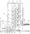
Shown in Figure 2 is the sectional view of the duplicating machine of a double-sided copying simultaneously according to an embodiment of the invention.
Shown in Fig. 2 A be one and be used for the contact roller of duplicating machine as shown in Figure 2 that this roller was shifted before toner-particle is fixed on the described roll web at last together with the toner image that several other devices are used to reduce on the roll web;
Be a contact roller shown in Fig. 2 B, it connects the toner image that same simple device is used to reduce on the roll web and was shifted before toner-particle finally is fixed on the described roll web;
Fig. 3 and Fig. 4 represent is the synoptic diagram of the xsect of the part of duplicating machine as shown in Figure 2, is that the discharged-area development mode is worked, and shown in these views is first three station, owing to be the purpose that is used for comparison, Fig. 3 and Fig. 4 are incomplete.
What Fig. 5 represented is a kind of improved form as shown in Figure 4.
Fig. 3 A, Fig. 4 A are similar with Fig. 5 to Fig. 3, Fig. 4 with Fig. 5 A, but shown duplicating machine is worked in the chemical development mode.
Fig. 3 B is similar to Fig. 3, but shown duplicating machine has been used opposite polarity drum and toner-particle on adjacent printing head.
Shown in Figure 6 is transferred image and the generalized schematic that makes it alignment.
It shown in Fig. 6 A the enhancing frequency circuit that is used for according to duplicating machine of the present invention.
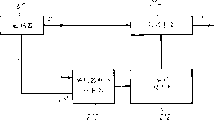
Shown in Figure 7 is the synoptic diagram of alignment control device, is used at duplicating machine according to the present invention the alignment of image being controlled.
Shown in Figure 8 is the detailed maps of the embodiment of a control circuit, and this circuit is used at duplicating machine according to the present invention the alignment of image being controlled, this figure separated into two parts:
Shown in Fig. 8 A bias table (offset table) program stack, scrambler and roll web location counter;
Shown in Fig. 8 B comparator circuit and image transfer printing station A.
Shown in Figure 9 is an alternate embodiment that is used at duplicating machine according to the present invention image being carried out the control circuit of alignment control.
Shown in Figure 10 is the simplified schematic diagram of the formation of coding correcting device.
Shown in Figure 11 is an alternate embodiment that is used for according to station setting of the present invention.
In following description, described image is that the mode with discharged-area development forms.The professional is appreciated that same principle also can be applied to the figure of chemical development form.
As shown in Figure 1, each image produces station and comprises a columniform drum 24, and it has photoconductive outside surface 26.What be arranged in drum 24 circumferencial directions is a main charger 28, it can give drum surface 26 charging equably, for example can reach-current potential of 600V, an exposure station 30, for example, can be scanning laser beam or light emitting diode matrix, by make bulging photoconductive surperficial 26 exposures with image state (image-wise) or line (line-wise), and cause that the electric charge on the latter is selectively eliminated, for example reach-the 250V current potential, the form that charging charge is distributed with Graphic State is stayed on the drum surface 26.This so-called " sub-image " can take developer on the drum surface 26 to by a development station 32, makes it to be rendered as visible image.Development station 32 comprises a developer drum 33, and it is mounted to adjustable, make it can along its radially near or leave drum 24, its principle will be in following further explanation.According to an embodiment, comprise (i) toner-particle in the developer, this particle comprises the dyestuff of a kind of resin, a kind of suitable color or pigment and the control of a kind of electric charge and can make toner have the potpourri of the electropolar compound of friction of needs and the carrier particle that (ii) has toner-particle by contact friction.Carrier particle can be made by magnetic material, as iron or iron oxide.In the typical structure of this development station, development drum 33 comprises that an inside has the turnbarrel of magnet, so that toner and magnetisable carrier particle be by rotation and mix mutually, and contacts with the surface 26 of drum 24 mode with brush shapes.The negative charge toner-particle, obtaining certain level by triboelectric charging for example during 9 μ C/g, be subjected to the effect of electric field between these zones and the negative charge bias voltage developer, and attracted to the image exposure zone on the bulging surface 26, thereby it is visible that sub-image is become.
After the development, be bonded at the toner image on the drum surface 26, be transferred on the roll web 12 of motion by corona transfer (corona tranfer) device 34.The roll web 12 of motion contacts with about 15 ° winding angle ω face-to-face with bulging surperficial 26, and angle ω depends on the position of guide roller 36.The corona transfer device is contained on the another side with the corresponding roll web of drum, and have one with toner-particle on the opposite polarity noble potential of electric charge, thereby toner-particle is drawn down from drum surface 26, and be attracted on the surface of roll web 12.Typical corona transfer device has the corona wire that is positioned at the about 7mm biography of the frame of leaving around it, and it is far away that it also leaves paper roll coil paper 7mm.Typical corona transfer electric current is approximately along web width 3 μ A/cm.Corona transfer device 34 also plays the effect that produces a powerful clinging power between roll web 12 and drum surface 26, cause being synchronized with the movement of drum surface 26 and roll web 12 like this, thereby impel the surface of toner-particle and roll web 12 to contact securely.Yet, more than by the determined position of corona transfer device 34 positioning actions, roll web then should not be wrapped on the drum, therefore, the circumferential position place of the drum on the position of corona transfer device 34 is provided with a roll web discharge corona (Web discharge corona) device 38, and this device is driven by alternating current, be used to remove the electric charge on the roll web 12, and make roll web 12 be released from drum surface 26.To leave drum surperficial 26 the time when roll web, and roll web discharge corona unit 38 has also played the effect of eliminating electric spark.
Then, drum surface 26 is pre-charged to a current potential by a precharge charger 40, for example-and 580V.Precharge makes the last charging of being finished by charger 28 to drum become easy.Any residue toner that also is bonded on the cylinder surface can more easily be disposed by known scavenge unit 42.The last vestige of electrostatic image in the past is recharged device 28 and wipes.Scavenge unit 42 comprises an adjustable removing brush 43, and its position can be transferred to close or leave drum surface 26, to guarantee best removing effect.The removing brush is grounded or reaches such current potential corresponding to drum, and promptly it can draw down the lip-deep residue toner-particle of drum.After the removing, the drum surface can enter the next record cycle.
With reference to figure 1 and Fig. 2, (see duplicating machine 10 among Fig. 2) after by first station A simultaneously, roll web produces printing head B, C and D by image continuously, and at this, the image of other color is sent on the roll web.The accurate alignment of a plurality of images that produced by continuous station is vital.In order to finish this alignment, each station is handled the necessary strict timing zero hour of image.Yet the accurate alignment between the image is only possible when only not sliding between roll web 12 and drum surface 26.
Static clinging power between roll web and drum is produced by device 34, winding angle ω depends on the relative position between drum 24 and the guide roller 36, because the driving action of drive roller 22, produced tension force on the roll web, and effective braking of detent 11, the rotational speed that guarantees drum 24 only depends on the motion of roll web 12, thereby has guaranteed that the motion of cylinder surface and roll web are synchronous.
Duplicating machine 10 according to the present invention has one to supply with station 13, and a reel 14 that is wound with the material web 12 of sufficient amount on it is equipped with in the inside, and the length of material web 12 makes can print 5000 images thereon at most.Roll web 12 is sent in the casing 44 of duplicating machine of a turriform, and support column 46 and 46 ' is installed therein, is provided with 5 similar station A to E and A ' above each to E '.Image produces station A, B, C and D and same A ', B ', C ' and D ' and is mounted respectively to duplicating yellow, dark red, blueness and black image.The setting of station E and E ' is in order to duplicate a kind of other additional color, and for example a kind of specific especially color is as white.Each station group, A arrives E ' to E or A ', is installed into vertical substantially structure, thereby has reduced floor area.Pillar 46 and 46 ' is made into vibration-proof structure, and method is in its lower section the flat board 48 support spring 50,51 to be housed.Pillar 46 and 46 ' can be mounted they can be relatively moved.Like this, pillar can be removed when maintenance relatively.
After leaving last image and producing station E ', the path of roll web 12 is touched roller 150 and oppositely comes, and this roller cooperates with device shown in Fig. 2 A and 2B, with elimination toner deposition in its surface.Image on the roll web is fixed by the device in the photographic fixing station 16, can also be transmitted into shearing station 20 (meaning as shown in the figure) then through a cooling station 18 thereafter, and a collecting box 52 also can be arranged if necessary.
Roll web 12 is transmitted through duplicating machine by two drive roller 22a and 22b, and an one drive roller produces between the station A supplying with station 13 and first image, and second at photographic fixing station 16 with shear between the station 20.Drive roller 22a, 22b is driven by controllable motor 23a and 23b.One speed Be Controlled among motor 23a, the 23b, promptly its rotational speed can make roll web with the speed of needs by duplicating machine, this speed for example can be and reaches about 125mm/ second.Another motor is a control torque, so that roll web produces tensile force, for example reaches along the about 1N/cm of web width.
As signal in more detail among Fig. 2 A, in duplicating machine shown in Figure 2, image receives roll web 12 and moves by a rotatable contact roller 150 of freedom along a roll web transfer path.Contact roller 150 has the fuse of a conduction, has covered one deck insulating material on it, preferably a kind of smooth cohesionless material, and as fluorinated polymer, preferably teflon such as Teflon (TEFLON), available electric discharge device fills static to it.Roller surfaces 154 does not have for toner-particle or toughness seldom.
The winding angle of roll web on contact roller 150 is approximately 135 °.Roll web 12 is loaded with the toner image that has static on its two sides.The linear movement of thin slice 12 is maintained in synchronous with the peripheral speed that contacts roller 150, and this is that freedom can be changeed because of the latter.Make potential difference (PD) of generation between roller 150 and the roll web 12 by a charger 151 by direct drive.Thereby roll web 12 in the zone that contacts with roller by electrostatic attraction so that be in the roller 150 that a fixing current potential preferably is in earthing potential, driven by roll web 12 and slide and take place, thereby the phenomenon that toner image is erased can not take place.
One is installed 152 by the electrically driven (operated) corona discharge of interchange (discharging corona) and makes roll web 12 easily break away from roller surfaces 154.
According to the embodiment shown in Fig. 2 A, in the upstream of contact roller 150, roll web 12 passes through between the 158L from a pair of opposite polarity charger 158R.Therefore, it is identical to be loaded in the polarity of the lotus flux that charges of polarity that the toner-particle (this outside surface with counter-drum 150 between do not contact) of the outside surface of roll web 12 obtains and corona unit 151.
Although this is to corona unit 158L, 158R can be made up of opposite polarity direct-current discharge device, because the negative polarity DC corona produces an inhomogenous unloading along its length direction easily, thereby the negative polarity DC corona device that replaces in the aforesaid a pair of corona unit with an AC corona device is favourable.This ac equipment and a positive polarity DC corona device are linked together, are arranged in the relative two sides of roll web 12, therefore can produce more uniform pure negative charge.
Toner-particle is to being grounded or being in transmission on the contact roller 150 of set potential, charging by corona unit 153 pair of rollers surfaces 154 is offset, with before the roll web 12 that is loaded with toner image contacts, preferably a kind of corona charging of this charging.The charge polarity of aforesaid corona unit 153 is identical with the polarity of toner-particle, and this toner-particle will contact with roller surfaces 154.
Any residue toner that may be bonded on the roller surfaces 154 after roll web 12 breaks away from roller 150, will be eliminated device 155 and remove.Scavenge unit 155 comprises that is removed a brush 156, and it is with the rotation directions rotation identical with contact roller 150.Removing brush 156 is grounded or determines and the residue toner-particle of adhering drawn down a current potential from roller surfaces 154.
In the another kind of embodiment as shown in Fig. 2 B, make roll web 12 tensionings of contact on the roller 150 with enough mechanical tensioning power, the corona unit 151 and 152 that provides static charge to make so to attract each other between roll web and the roller and break away from can save.And, in this case, will have a sufficiently high reversed polarity charge potential with respect to the charging charge of corona unit 153 with the surperficial contacted toner-particle that contacts roller 150, so paired corona unit 158R, 158L can be omitted, and can not cause the image remarkable topotype essence that becomes by touch roll sub-surface 154 time unclear.
With reference to figure 3, the figure shows roll web 12 and drum 24a, 24a ' and 24b, they belong to respectively as shown in Figure 2 that three staggered images of duplicating machine produce station A, A ' and B, and these stations carry out work in the discharged-area development mode. Corona transfer device 34a, 34a ' and 34b match with described station.
Referring to the amplifier section among Fig. 3, as can be seen, produce station A place at image, drum 24a goes up and is filled with negative charge, is loaded with the negative charge toner-particle on its surperficial 26a, shown in small circle.Corona transfer device 34a provides positive ion stream, and the bulging 24a that is filled with negative electricity that this positive ion stream is adjacent attracts, thereby is deposited on the one side 12R of roll web 12.Positive charge on the face 12R attracts mutually with the negative charge toner-particle of first kind of color, and the latter is deposited on the face 12L of roll web 12.
With reference to the amplifier section in the middle of the figure 3, as can be seen, when the roll web 12 that is loaded with the negative charge toner-particle on its face 12L arrives image generation station A ', corona transfer device 34a ' provides positive ion stream, make it to deposit on the face 12L of paper roll coil paper 12, the polarity of the electric charge on the toner-particle is just become by negative.At this, the negative charge toner-particle deposits on the face 12R of roll web 12 from drum 24a '.
Enlarged drawing with reference to figure 3 middle and upper parts, as can be seen, when roll web 12 carried positive charge arrival image generation station B place on its face 12L, corona transfer device 34b provided positive ion stream, and make it to be deposited on the face 12R of roll web, cause the toner-particle on this face to become positive.At this, the negative charge toner-particle of second kind of color (shown in the circle of band pore) is deposited on the face 12L of roll web 12 from drum 24b.Yet when the positive charge toner-particle of first kind of color on face 12L arrived negative charge drum 24b, they were attracted, and the repulsive force that is produced by corona transfer device 34b promotes again, so may come off from roll web.The toner-particle that comes off in this mode has caused the loss of color depth in last duplicating, and the displacement of toner-particle may take place the boundary between image.
Shown in Figure 4 is the solution of this problem.In the front that the 3rd image produces station B, and relative image is produced (not diagram) between the station, each face place that a pair of opposite corona unit (coronadevice) 58L and 58R are installed in roll web 12 respectively in its subsequently each.The polarity of corona unit 58L and 58R be selected as and be loaded in two opposite face 12R of roll web 12 and the toner-particle on the 12L with opposite polarity.Can find out from the amplifier section of Fig. 4, between printing head A ' and B, positively charged toner-particle on the face 12L of roll web 12, when they pass through negative charge corona unit 58L, become electronegative, when the electronegative toner-particle on the face 12R of roll web 12 passes through positive charge corona unit 58R, become positively charged.From the amplifier section on Fig. 4 top as can be seen, the toner-particle of first kind of color on the face 12L is electronegative now, when their arrival is filled with the bulging 24b of negative charge, they are subjected to the thrust that drum 24b goes up electric charge, thereby avoid them to fall down from the paper roll coil paper, the positive charge that comes from corona transfer device 34b is also supported.Thereby the roll web toner-particle that carries first, second kind color of institute's requested number according to the image that is produced on its face 12L continues to enter the next station in the duplicating machine.
Fig. 5 is similar to Fig. 4, but roll web discharge corona unit (web discharge coronadevice) 38a, 38a ' and 38b have also been illustrated in addition, they match with corresponding station, be used to reduce the positive charge on the roll web adjacent surface, prevent that the transfer printing gap between roll web and drum from producing electric spark.
In Fig. 4, corona unit 58L and 58R are opposite polarity DC coronas, and this describes above having obtained.Because the negative charge corona produces irregular unloading at length direction easily, thereby be favourable with the alternative negative electricity DC corona device of an AC corona device.This AC corona device 58L matches with positive electricity DC corona device 58R, produces a kind of pure negative charge of marshalling.
Duplicate although the image that carries out with " counter-rotating " visualization way has been described among Fig. 3,4 or 5, this is clearly to the professional, and promptly identical general principle can be applied in the duplicating of " directly " development.So, with reference to figure 3A, wherein showing bulging 24a, 24a ' and the 24b of three staggered image generation stations in roll web 12 and the duplicating machine as shown in Figure 2, they are operated in the chemical development mode. Corona transfer device 34a, 34a ' and 34b match with aforesaid those stations.
With reference to the amplifier section of figure 3A middle and lower part, as can be seen, be loaded with positively charged toner-particle on the surperficial 26a of negative charge drum 24a, shown in small circle.The bulging 24a that has negative charge that the negative ion stream that corona transfer device 34a is provided is adjacent is deposited on the face 12R of roll web 12 in the effect of certain orientation.Between the positive charge toner-particle of the negative charge on the face 12R and first kind of color, attract each other, the latter is deposited on the face 12L of roll web 12.
Amplifier section with reference to figure 3A middle part, as can be seen, when the roll web 12 that is loaded with the positive charge toner-particle on its face 12L arrives image generation station A ', the negatively charged ions stream that corona transfer device 34a ' is provided is deposited on the face 12L of roll web 12, has caused the charge polarity of toner-particle to become just into negative.At this, the positive charge toner-particle is deposited on the face 12R of roll web 12 from drum 24a '.
Amplifier section with reference to figure 3A top, as can be seen, when the roll web 12 that is loaded with the negative charge toner-particle on its face 12L arrives image generation station B, corona transfer device 34b provides negative ion stream, this negative ion stream is deposited on the face 12R of paper roll coil paper, and causing the anti-property of toner-particle on that face is negative electricity.At this, the toner-particle of the positively charged of second kind of color, as have shown in the small circle of stain, 24b deposits on the face 12L of roll web 12 from drum.Yet when the toner-particle that has negative electricity of first kind of color arrived regional on the surperficial 24b of drum, they were promoted by the repulsive force that corona transfer device 34b produces, and can come off from the paper surface.This of toner-particle comes off, and causes the loss of color depth in last printing, and the dislocation of toner-particle can take place on the border between the color.
It shown in Fig. 4 A this way to solve the problem.Before the 3rd image produces station B, and produce (not diagram) between the station at its two adjacent images subsequently, a pair of opposite polarity corona unit 58L and 58R are mounted respectively the both sides at roll web 12.It is opposite that the polarity of corona unit 58L and 58R is selected to the polarity that goes up contained toner-particle with the opposite face 12R and the 12L of paper roll coil paper 12.From Fig. 4 A amplifier section as can be seen, between station A ' and B, the negative charge toner-particle on 12 12L of roll web is had positive charge by anti-property one-tenth when it during by positive electricity corona unit 58L; Positive charge toner-particle on the face 12R of roll web 12 is when it is loaded with negative charge by anti-property one-tenth during by negative electricity corona unit 58R.From the amplifier section of Fig. 4 A middle and upper part as can be seen, the toner-particle of first kind of color on face 12L, when their arrive image and produce station B, become and had positive charge, and attracted by the attractive force that negative polarity corona transfer device 34b produces and be held on paper.Thereby according to the generation image, the toner-particle that roll web is loaded with first, second kind color of institute's requested number continues to enter the next station of duplicating machine on its face 12L.
Fig. 5 A is similar to Fig. 4 A, but also illustrates the roll web discharge in addition.Corona unit 38a, 38a ' and 38b, they match with separately station.
Opposite polarity between drum by utilizing adjacent stations and the toner-particle, it is possible avoiding the problem shown in Fig. 3 and Fig. 4, as shown in Fig. 3 B.
With reference to figure 3B, the figure shows bulging 24a, 24a ' and the 24b of three staggered stations of roll web 12 and duplicating machine shown in Figure 2, they are worked in the mode of discharged-area development. Corona transfer device 34a, 34a ' and 34b match with these described stations.
With reference to the amplifier section of figure 3B middle and lower part, positive charge drum 24a is loaded with the positive charge toner-particle on its surperficial 26a as can be seen, shown in small circle.Corona transfer device 34a provides negatively charged ions stream, and this ion flow is attracted by adjacent positive charge drum 24a, and is deposited on the face 12R of roll web 12.Cause the latter to be deposited on the face 12L of roll web 12 in the attraction between the positive charge toner-particle of the negative charge on the face 12R and first kind of color.
Amplifier section with reference to figure 3B middle part, as can be seen, when the roll web 12 that is loaded with the positive charge toner-particle on its face 12L arrives image generation station A ', corona transfer device 34a ' provides positive charge ion stream, this ion flow is deposited on the face 12L of roll web 12, causes the electric charge of toner-particle to be maintained positive charge.At this, the negative charge toner-particle is by from the face 12R of drum 24a ' deposition roll web 12.
Amplifier section with reference to figure 3B top, as can be seen, when the roll web 12 that is loaded with the positive charge toner-particle on its face 12L arrives image generation station B, corona transfer device 34b provides negative ion stream, this negative ion stream is deposited on the face 12R of roll web, causes the toner-particle on this face to be maintained electronegativity.At this, the toner-particle of second kind of color, as have shown in the small circle of stain, 24b deposits on the face 12L of roll web 12 from drum.When first kind of color positive charge toner-particle on the 12L arrived positive charge drum 24b face to face, the attractive force that they are resulted from corona transfer device 34b attracted, and is retained on the surface of paper.
Yet the layout as shown in Fig. 3 B is not best, because this solution makes that the parts at whole station places all are that this identical advantage has not existed.And the restriction more suffered than the selectable range of negative charge color toner of the selectable range of positive charge color toner is many, reason that why latter is had a preference in copier applications especially that Here it is.
With reference to figure 6, in order to describe the operating process of alignment control in detail, we define:
---write an A
1, B
1, C
1And D
1, being positioned at the such position on the drum of A, B, C, D station, this position carries out writing fashionable position perpendicular to the projection of its drum for these stations;
---transfer printing point A
2, B
2, C
2And D
2, at the surperficial 24a of drum, 24b, on 24c and the 24d, and with the center of the winding angle ω (see figure 1) that coincides;
---length l
A2B2, l
B2C2And l
C2D2Expression along the web length direction at an A
2And B
2, B
2And C
2And C
2And D
2Between distance;
---length l
A1A2, l
B1B2, l
C1C2And l
D1D2Expression along the drum surperficial 24a, 24b, 24d and 24s direction at an A
1And A
2, B
1And B
2, C
1And C
2And D
1And D
2Between length.
For the alignment that obtains, from A
1Point writes an image and arrives at B
1, C
1Or D
1The point place writes and should move through apart from l with roll web the time delay between the relevant image
AB, l
ACOr l
ADTime equate, here:
l
AB=l
A1A2+ l
A2B2-l
B1B2And thereby have:
l
AC=l
A1A2+ l
A2B2+ l
B2C2-l
C1C2With
l
AD=l
A1A2+l
A2B2+l
B2C2+l
C2D2-l
D1D2
In fact, length L
A1A2Deng and L
A2B2Nominally Deng what be designed to usually to equate, but because manufacturing tolerance, less difference is inevitably, for the purpose of alignment principle is described, supposes that they are unequal.
From top equation, draw the possible cause of an alignment failure (mis-registration) easily, just ought use regular time:
t
AB=l
AB/ V is on average at B
1The image of point compares A
1The picture delay of some time t so
AB, and when the speed V of roll web changed in this time, roll web with the length of passing by was:
l’
AB=∫
o tABVdt
Because l ' probably
ABWith l
ABUnequal, be written on B
1The image of point in the time of on being transferred to roll web, and is written on A
1The image of point can not alignment, thereby causes the alignment failure.
Suppose f
EThe pulsed frequency that expression is produced by scrambler 60, f
EEqual nf
D, n is a total quantity; Line frequency (line frequency) f
DFrequency (the f of line number is duplicated in expression
D=V/d), d is a line-spacing.
The displacement of the pulse unit of the representative roll web of each scrambler (ρ=d/n).Roll web relative position is at any time determined by the umber of pulse Z that results from scrambler.
Suppose that relative distance l equals the distance that roll web has been walked in preset time, thereby: Z=l/ ρ
According to above l
AB, l
ACAnd l
ADDefinition, we can determine:
Z
AB=Z
A1A2+Z
A2B2-Z
B1B2
Z
AC=... Deng.
Thereby, by many pulse Z of scrambler generation
AB, make B
1The image of point writes with respect to A
1The image write latency of point, therefore when they were transferred on the roll web, it was sure that two images are consistent.And that how this linear velocity that meets with roll web changes is irrelevant, suppose certainly 24a to the rotation of 24d all the time with the displacement synchronous of paper roll coil paper, as described above.
Although scrambler as shown in Figure 6 60 is installed on the independent roller of front of station A to D, preferably it is installed on bulging 24a in the 24d, i.e. one of centre of these drums preferably.Like this, the drum that scrambler is housed and and its drum farthest between web path be reduced to the shortlyest, therefore, reduced any uncertain elongation and l that results from roll web 12
A2B2Deng the out of true that distortion caused, and these distortion are because the drum or the off-centre of guide roller cause, and drum and guide roller define winding angle (ω).
Typical optical encoder device comprises the scale on the circumference of drum that diameter is 140mm of being engraved in of 650 equal intervals, and these scales are in the visual line of sight of a fixing optical detecting gear.If line-spacing is 40 μ m, then per 16 row produce a pulse.
Be depicted as scrambler 60 with reference to figure 6A, it comprises a scrambler dish 206 and an enhancing frequency circuit.Enhancing frequency circuit has extraordinary Phase Tracking characteristic, amplifies the incoming frequency fs of code sensor by a constant integer m.For the alignment solution that obtains, m should choose enough greatly, makes:
f
E=m·f
S=n·f
D
So: f
S=nf
D/ m
f
SCompare f
DFor a short time be necessary, and m must be bigger than n.
It is f that a voltage-controlled oscillator 203 produces a frequency
ESquare-wave signal.This frequency by frequency divider 204 by m remove a frequency f
m, its phase place Qm is by phase comparator 205 and incoming frequency f from code sensor 201
SPhase place Qs relatively.
Low-pass filter 202 elimination phase differential Qs-Qm make it to become DC voltage Ve, voltage are delivered to voltage-controlled oscillator 203 again.
Owing to have good Phase Tracking characteristic, the phase differential of Qs and Qm is near zero.Owing to increase effect frequently, at f
EOn have than big m phase place limit doubly between two encoder detector input pulse limits.Each f
EThe phase place limit represent a displacement d/n of roll web.
The high frequency that low-pass filter 202 is got rid of in the coded signal changes, and these high-frequency signals are normally incoherent with the web velocity variation, are the interference that is caused by vibration.
The time constant of low-pass filter 202 has been determined the frequency of response frequency raiser, to realize cutoff frequency, for example a 10Hz.
With reference to figure 7, it is f that scrambler 60 produces a frequency
ESignal, f
ECompare frequency f
DHigh n times, frequency f
DResult from by one of roll web 12 walking and equal the scramble time that the distance of line-spacing d is spent.For the duplicating machine (line-spacing d=42.3 μ m) of a kind of 600dpi, the frequency f that the web velocity of 122.5mm/s produces
D=2896Hz.
A roll web location counter 74 can calculate the umber of pulse that scrambler 60 produces at any time, and the relative position Z of a roll web has been indicated in the output of counter, a basic displacement of the incremental representation roll web of each Z, and promptly ρ is the 1/n of line-spacing d.
Postpone meter apparatus 70 and stored the numerical value Z that presets
AB, Z
ACAnd Z
AD, they with from writing the A of first image to the drum 24
1Point beginning writes the some B of image on drum 24b, 24c and the 24d subsequently finally
1, C
1And D
1The basic displacement number of roll web that the moment at place calculates equates, thereby whole subsequent image positions will be accurately corresponding with the position of first image on the later roll web 12.Adjusting gear 70a will be below with reference to Fig. 9 discussion.
The quantity of N=copy image;
Z
LThe length of=image can be expressed as the multiple of the basic displacement of roll web;
Z
S=provided (also can be expressed as the multiple of the basic displacement of roll web) in the gap between two images on the paper.
Program stack can calculate Z subsequently
A, iZ
D, l
When " beginning " signal is issued (signal that makes the duplicating machine entry into service)
(suppose that first image is from position Z
0+ Z
1The place begins, here Z
0The position of expression roll web when sending " beginning " signal) have following table to set up then:
Table 1Z
A, 0=Z
0+ Z
1Z
B, 0=Z
0+ Z
AB+ Z
1.... Z
D, 0=Z
0+ Z
AD+ Z
1Z
A, 1=Z
0+ Z
L+ Z
S+ Z
1Z
B, 1=Z
A, 1+ Z
AB+ Z
1.... Z
D, 1=Z
A, 1+ Z
AD+ Z
1
=Z
0+Z
L+Z
S+Z
AB+Z
1 .... =Z
0+Z
L+Z
S+Z
AD+Z
1
. .
. .
. .
. .
. .
. .
. .?Z
A,i=Z
0+i(Z
L+Z
S)+Z
1 Z
B,j=Z
0+Z
AB+j(Z
L+Z
S)+Z
1 .... Z
D,l=Z
0+Z
AD+l(Z
L+Z
S)+Z
1
Image writes station 73, receives start pulse signal S
ATo S
D, just begin to write station A and write image to the D place at image.In case image begins to write, the remainder of this image is with a line frequency f
DBe written into, this frequency results from:
f
D=f
E/N,
Like this, frequency f
DSynchronous with coding output, when start pulse signal was received, phase place was adjusted to 0.
Device described above of course not limits and only is used for carrying out the control of image registration on the paper, but also can be used in the accurate roll web position signalling that generation can be copied any component recognition of machine.These assemblies are for example sheared station 20, collecting box 52 (see figure 2)s.
With reference to figure 8A and 8B, when " beginning " that make the duplicating machine entry into service when pulse signal sends, register 80 storages are summation Z down
0+ Z
1, this summation is calculated by totalizer 89.Multiplexer (multipliexer) 81 is delivered to register 82 with this numerical value.Totalizer 85,86 and 87 is calculated Z then
* B, j, Z
* C, kAnd Z
* D, l, j wherein, k and l are 0, and these numerical value are precalculated positions of roll web, and in this position, first image transmits station at the image of correspondence to begin to write.Z
* A, i, when i is 0, certain and Z
0+ Z
1Equate.With postponed for 1 a period of time that equates after, these numerical value are stored among (first in first out) FIFO storer 90A, 90B, 90C and the 90D, wherein only 90A is concisely illustrated.Simultaneously, totalizer 83 and 84 has been passed through Z
* A, 0+ Z
L+ Z
SWith Z
* A, 1Calculate, this numerical value is sent to register 82 by multiplexer 81.Totalizer 85,86 and 87 and then from Z
* A, 1Calculate numerical value Z
* B, 1, Z
* C, 1And Z
* D, 1, they are stored among FIFO90A or the like again.This process is proceeded up to reaching 0 by subtracting register 88, and wherein numerical value starts from N and along with writing pulse each time with series of values Z
* A, iTo Z
* D, lStore among the FIFO and successively decrease.When this took place, all images write the starting position and is calculated and stored in the push-up storage in chronological order.
Simultaneously, comparer 91A etc. is constantly with roll web position Z and numerical value Z
A, i, to Z
D, lRelatively, when it read from FIFO, i was 0 when l begins.As Z and Z
A, 0When equating, signal S
ABe issued, it makes divider 92A reset (seeing Fig. 8 B), f like this
DThe phase place of signal and S
APulse signal is synchronous, and this is owing to the aforesaid precision that has improved the by-pass alignment produces.Row register 93A is also returned zero, and it is addressing Y=0 in image memory 95A.For f
DEach pulse signal of signal, picture point register 94A produce a series of by the pixel address X that adds counting.When this image memory was construed to the two-dimensional arrangement of pixel, calculating pixel address X with the speed of being determined by the signal pixels clock, produced a pixel number stream, and they are fed to write head 30, cause photoelectric conducting drum surface 26 to be exposed with line mode.For f
EEvery n pulse signal of signal, next pixel column is sent to write head.By this way, the alignment of different images not only image to begin be accurate, and in image, keep precision.
Image write at the beginning S
ATo S
DSignal just causes next step numerical value Z
A, iTo Z
D, lFrom first in first out reservoir 90A, be read or the like.So following one page image will be from predetermined.
In the preferred embodiments of the present invention shown in Fig. 9, the essential part of operation circuit realizes its function by software program, this software program is carried out by a little process chip, in this situation, the repertoire that circuit among Fig. 8 A provides, except that scrambler, replaced by software coding, thereby the dirigibility of control circuit is provided.
The numerical value Z that calculates
* A, iTo Z
* D, lPreferably be stored in the one or more sorted tables 100 in the microprocessor memory.In hardware solution, the roll web position Z that comparer 72 continuously provides first input and roll web location counter 74 relatively, this is preferably by software but can be by hardware supported.Once after finding these two values match, microprocessor is assert each signal S respectively
ATo S
D
For check register, the operator once duplicates test, and the product that runs off is measured out with Δ with wherein any registration failure by scrutiny.Umber of pulse correction signal that equates with Δ/ρ then with known method from numerical value Z
ABDeng in add or deduct, this numerical value is stored in by adjusting gear and postpones in the meter apparatus 70.
With reference to Figure 10, in order to proofread and correct the cycle of each independent pulse of exporting from encoder detector, scrambler 60 produces an additional signal I, and it plays the effect of an index for coded signal P.When code sensor 60 comprises a disc that has many interval flag, and it is when being read in by first optical sensor, produce the pulse of determining web displacement, signal I is produced by second optical sensor, therefore for the rotation weekly of scrambler disc, produce a pulse signal.Therefore, it is for referencial use that this encoder pulse count device 210 is used extra-pulse, and by a multidigit binary signal, identification results from each pulse P of first optical sensor.Scrambler table of corrections 212 preferably is included in the reservoir such as a kind of read-only memory able to programme (PROM) that some data are difficult for losing, and storage has the predetermined multidigit binary periodic for each independent encoder pulse P to proofread and correct numerical value.In order to make the coding means for correcting reduce cycle of specific pulse, this cycle is proofreaied and correct the summation that numerical value is positive set time and positive or negative correction time.
Shown in Figure 11 is that a station A arrives a kind of different layouts of D ' with respect to the path of roll web to D and A '.The operation of this layout is clearly for those skilled in the art.Station can be arranged to level, vertical or other structure.
Relevant references
The characteristics of multiple duplicating machine as described herein are the themes of following relevant european patent application:
NOS:93304771.4, exercise question are " static one-way trip multistation duplicating machine ";
93304773.0 exercise question is " the static one-way trip multistation duplicating machine with alignment control ";
93304774.8 exercise question is " a roll web conditioning equipment ";
With 93304775.5, exercise question is " Xerox of imaging on the roll web that moves "
Above-mentioned whole application all proposes on June 18th, 1993.
Claims (26)
1, a kind of eletrophotography one-way trip multistation duplicating machine of imaging on roll web, this duplicating machine comprises:
---at least three toner images produce static station (A, B, C, D, A ', B ', C ', D '), and wherein each has a rotatable continuous surface (26), can form toner image thereon;
---be used to transmit the drive unit (22) that roll web (12) passes through described station (A, B, C, D, A ', B ', C ', D ') continuously;
---be used for the toner image on each rotatable continuous surface (26) is transferred to transfer device (34) on the roll web (12); It is characterized in that:
Image produces station (A, B, C, D, A ', B ', C ', D ') and is divided into two groups, the rotatable continuous surface (26) of a group is staggered with the rotatable continuous surface of another group, thereby enables to carry out simultaneously double-sided copying.
2, duplicating machine as claimed in claim 1 is characterized in that: described image produces station by interconnected at the relative place, two sides of roll web (12) one by one.
3, duplicating machine as claimed in claim 2, it is characterized in that: also comprise corona unit (58L, 58R), they are used for the polarity of the static charge that exists in the toner on the roll web (12) is controlled, this control be positioned at the 3rd image produce station and thereupon after each image produce before station, to guarantee that can not produce the station place to the image of front in the transfer printing that the 3rd and any later image produce the toner image at station place be transferred to image on roll web (12) identical faces and produce and destroy.
4, as claim 2 or 3 described duplicating machine, it is characterized in that:
---the toner image that is transferred on the roll web (12) by each image generation station has identical charge polarity;
---produce station backward from second image, produce between the station at every adjacent image, corona unit (58L, 58R) be set up, be used for before the toner on the one side that is deposited on roll web (12) arrives next image generation station, and, the polarity of toner is restored by after the corona transfer device of previous station (B).
5, duplicating machine as claimed in claim 4, it is characterized in that: it comprises that three above-described images produce stations, and the device that is used to toner image polarity is restored is set at second and the 3rd image produces between the station and subsequently each produces between the station described image.
6, as claim 4 or 5 described duplicating machine, it is characterized in that: the device that is used to make the polarity of toner image to restore comprises a corona unit.
7, duplicating machine as claimed in claim 6 is characterized in that: corona unit comprises an AC corona device, and it has the pure electric charge output identical with the original polarity of the toner charge that is transferred of a polarity in next one development station.
8, duplicating machine as claimed in claim 7 is characterized in that: this AC corona device is set on the web path and an one side place that the positive charge DC corona is relative.
9, as the described duplicating machine of any claim in front, it is characterized in that: an interchange roll web discharge corona unit (38) is provided on the corona transfer device (34), thereby roll web (12) can be thrown off from rotatable continuous surface (26).
10, as the described duplicating machine of any claim in front, it is characterized in that: described rotatable continuous surface (26) comprises a drum or band.
11, duplicating machine as claimed in claim 10 is characterized in that: described drum or bar have a photoconductive surface (26).
12, duplicating machine as claimed in claim 11 is characterized in that: each described toner image produces eletrophotography station (A, B, C, D, A ', B ', C ', D ') and comprising:
---main charger (28) is used for surface (26) charging to drum or band;
---exposure device (30) is used for making with image state the exposure of charging surface of drum or band;
---a development station (32) is used for toner is deposited on drum or the strip face by the zone of photo-induced discharge.
13, duplicating machine as claimed in claim 12 is characterized in that: development station (32) comprises the potpourri of a kind of toner-particle and conductive carrier particle.
14, duplicating machine as claimed in claim 13 is characterized in that: described development station (32) comprises the device that is used to constitute Magnetic brush, and this Magnetic brush can adsorb the carrier granular that is loaded with toner thereon.
15, as the arbitrary described duplicating machine of claim 12 to 14, it is characterized in that: light emitting diode (30) array that is used on the charging surface of drum or band, comprising an image state modulation with the device of image state exposure.
16, as the described duplicating machine of any claim in front, it is characterized in that: the station of each group (A, B, C, D, A ', B ', C ', D ') is arranged in fact vertical structure.
17, as the described duplicating machine of any claim in front, it is characterized in that: described duplicating machine comprises a heating arrangement (16), is used for fixing them after toner image is transferred on each face of roll web (12).
18, as the described duplicating machine of any claim in front, it is characterized in that: described duplicating machine comprises that one is sheared station (20), is used for roll web out of the press is cut into sheet.
19, duplicating machine as claimed in claim 18 is characterized in that: described being used for toner image before the heating arrangement on the described roll web (16) is positioned at described shearing station.
20, as the described duplicating machine of any claim in front, it is characterized in that: aforesaid roll web (12) is sent to from reel (14).
21, as the described duplicating machine of any claim in front, it is characterized in that: be used to make roll web be transmitted continuously drive unit (22) by described station comprise be used to make roll web (12) under tensioning state with the rotational synchronization of rotatable continuous surface (26) be transmitted through the device of described image generation station.
22, duplicating machine as claimed in claim 21 is characterized in that: roll web (12) contacts the velocity of rotation that enables to control rotatable continuous surface (26) with viscosity between the rotatable continuous surface (26) synchronous with it.
23, duplicating machine as claimed in claim 22, it is characterized in that: each image produce station (A, B, C, D, A ', B ', C ', D ') comprise one can driven rotatable Magnetic brush (33) and one can driven rotatable removing brush (43), between both and the rotatable continuous surface (26) is rubbing contact, and described brush rotates with opposite direction.
24, duplicating machine as claimed in claim 23 is characterized in that: Magnetic brush (33) and remove the peripheral speed of brush (43) and they that the summation of the power on institute's rotatable continuous surface that is delivered to (26) is essentially is zero with the rubbing contact degree of rotatable continuous surface (26) separately.
25, as claim 23 or 24 described duplicating machine, it is characterized in that: a position with respect to rotatable continuous surface (26) in the described at least brush is adjustable, so that the big I of the rubbing contact power between brush and the rotatable continuous surface (26) is adjusted.
26, as the described duplicating machine of any claim in front, it is characterized in that: it also further comprises a rotatable contact roller (150) that contacts with described roll web, and this roll web at least with that surface that described roller (150) contacts on have the toner-particle image of static electrification lotus; Wherein said contact roller (150) matches with electrostatic charging device (153), before described roll web (12) and described surface (154) contact that contacts roller (150), this device (153) can be in the identical static charge of polarity of the toner-particle on the adjacently situated surfaces that provides on the surface of described contact roller (150) with described roll web.
Applications Claiming Priority (4)
| Application Number | Priority Date | Filing Date | Title |
|---|---|---|---|
| EP93304772 | 1993-06-18 | ||
| EP93304772.2 | 1993-06-18 | ||
| EP94302399.4 | 1994-04-05 | ||
| EP94302399A EP0677792B1 (en) | 1994-04-05 | 1994-04-05 | Electrostatographic copying or printing apparatus |
Publications (2)
| Publication Number | Publication Date |
|---|---|
| CN1098796A CN1098796A (en) | 1995-02-15 |
| CN1058095C true CN1058095C (en) | 2000-11-01 |
Family
ID=26134345
Family Applications (1)
| Application Number | Title | Priority Date | Filing Date |
|---|---|---|---|
| CN94107216A Expired - Lifetime CN1058095C (en) | 1993-06-18 | 1994-06-15 | An electrostatographic single-pass multiple station printer for duplex printing |
Country Status (13)
| Country | Link |
|---|---|
| US (1) | US5461470A (en) |
| EP (1) | EP0631204B1 (en) |
| JP (1) | JP2878968B2 (en) |
| KR (1) | KR100310589B1 (en) |
| CN (1) | CN1058095C (en) |
| AT (1) | ATE166730T1 (en) |
| AU (1) | AU671019B2 (en) |
| BR (1) | BR9402427A (en) |
| CA (1) | CA2125940C (en) |
| DE (1) | DE69410533T2 (en) |
| DK (1) | DK0631204T3 (en) |
| ES (1) | ES2117211T3 (en) |
| TW (1) | TW238371B (en) |
Families Citing this family (27)
| Publication number | Priority date | Publication date | Assignee | Title |
|---|---|---|---|---|
| DE69431239T2 (en) * | 1994-04-05 | 2003-04-17 | Xeikon Nv | Electrostatographic copier or printer |
| DE4431669B4 (en) * | 1994-09-06 | 2006-01-12 | Heidelberger Druckmaschinen Ag | Device for depositing different products produced by a printing press in continuous operation |
| US5805969A (en) * | 1995-08-10 | 1998-09-08 | Xeikon N.V. | Electrostatographic printer for imparting a modified finish to a toner image |
| US5701565A (en) * | 1996-03-29 | 1997-12-23 | Xerox Corporation | Web feed printer drive system |
| JP3454401B2 (en) * | 1996-09-19 | 2003-10-06 | 日立プリンティングソリューションズ株式会社 | Electrostatic recording device |
| JP3361715B2 (en) * | 1997-03-19 | 2003-01-07 | 富士通株式会社 | Image forming device |
| DE19755584A1 (en) * | 1997-12-15 | 1999-06-17 | Heidelberger Druckmasch Ag | Method and device for fixing toner images |
| JP2000131893A (en) | 1998-10-27 | 2000-05-12 | Fujitsu Ltd | Both-side printing device |
| JP3317908B2 (en) | 1998-11-16 | 2002-08-26 | 富士通株式会社 | Double-sided printing device |
| JP3320367B2 (en) * | 1998-12-08 | 2002-09-03 | 富士通株式会社 | Double-sided printing apparatus and control method for the same |
| JP3302337B2 (en) * | 1999-04-15 | 2002-07-15 | 富士通株式会社 | Double-sided printing device |
| JP3713165B2 (en) | 1999-07-12 | 2005-11-02 | 富士ゼロックス株式会社 | Continuous media printer |
| US6529697B1 (en) * | 2000-08-30 | 2003-03-04 | Hewlett-Packard Company | Methods and apparatus for calibrating inline color laser printers |
| US6466761B1 (en) | 2000-11-14 | 2002-10-15 | Xerox Corporation | Duplex transfer apparatus and processes |
| JP2002229276A (en) | 2000-11-30 | 2002-08-14 | Ricoh Co Ltd | Image forming device and method therefor and image forming system |
| US6880463B2 (en) * | 2001-08-24 | 2005-04-19 | Xeikon International, N.V. | Coating of toner images |
| US7099029B2 (en) * | 2001-09-14 | 2006-08-29 | International Business Machines Corporation | Method for aligning two or more independent printing systems with a single control unit and intelligent print controllers |
| JP2003262989A (en) | 2002-03-08 | 2003-09-19 | Hitachi Printing Solutions Ltd | Double-side printing device |
| US6905269B2 (en) * | 2002-07-03 | 2005-06-14 | Oki Data Americas, Inc. | System and method for continuous label printing |
| US7391425B2 (en) * | 2004-03-29 | 2008-06-24 | Eastman Kodak Company | Synchronous duplex printing systems using directed charged particle of aerosol toner development |
| US7539453B2 (en) | 2004-04-16 | 2009-05-26 | Ricoh Company, Ltd. | Printer capable of reserving sheet wrapping width |
| JP4208096B2 (en) * | 2005-03-18 | 2009-01-14 | シンジーテック株式会社 | Conductive roll inspection method |
| EP1939005A1 (en) * | 2006-12-28 | 2008-07-02 | Agfa Graphics N.V. | Synchronisation of front and back side printing in double sided inkjet web printing |
| JP4979449B2 (en) | 2007-04-27 | 2012-07-18 | キヤノン株式会社 | Fixing device |
| JP5156866B2 (en) * | 2012-04-13 | 2013-03-06 | キヤノン株式会社 | Fixing device |
| JP5780266B2 (en) * | 2013-06-26 | 2015-09-16 | 富士ゼロックス株式会社 | Image forming apparatus and powder coating apparatus |
| JP6142906B2 (en) * | 2015-09-28 | 2017-06-07 | カシオ計算機株式会社 | Static eliminator and image forming system |
Family Cites Families (9)
| Publication number | Priority date | Publication date | Assignee | Title |
|---|---|---|---|---|
| US3694073A (en) * | 1970-07-20 | 1972-09-26 | Xerox Corp | Method for duplexing |
| US4188110A (en) * | 1978-04-03 | 1980-02-12 | Xerox Corporation | Photoconductive belt supporting apparatus |
| JPS60169862A (en) * | 1984-02-13 | 1985-09-03 | Japan Steel Works Ltd:The | Multicolor electrophotographic apparatus |
| DE3406244A1 (en) * | 1984-02-21 | 1985-08-22 | Siemens AG, 1000 Berlin und 8000 München | LASER PRINTING SYSTEM FOR MULTICOLOR AND BACKSIDE PRINTING |
| US4968993A (en) * | 1986-12-16 | 1990-11-06 | L&C Family Partnership | Printing press |
| US4731631A (en) * | 1987-04-20 | 1988-03-15 | Xerox Corporation | Vertically oriented photoconductive drum |
| US4935785A (en) * | 1988-12-05 | 1990-06-19 | Xerox Corporation | Electrophotographic fuser roll and fusing process |
| DE3918127C1 (en) * | 1989-06-03 | 1990-12-13 | Man Roland Druckmaschinen Ag, 6050 Offenbach, De | |
| JPH05131608A (en) * | 1991-11-14 | 1993-05-28 | Tokyo Kikai Seisakusho Ltd | Multi-color printing machine |
-
1994
- 1994-06-08 US US08/257,116 patent/US5461470A/en not_active Expired - Lifetime
- 1994-06-11 TW TW083105320A patent/TW238371B/zh active
- 1994-06-13 EP EP94304260A patent/EP0631204B1/en not_active Expired - Lifetime
- 1994-06-13 AT AT94304260T patent/ATE166730T1/en not_active IP Right Cessation
- 1994-06-13 DK DK94304260T patent/DK0631204T3/en active
- 1994-06-13 ES ES94304260T patent/ES2117211T3/en not_active Expired - Lifetime
- 1994-06-13 DE DE69410533T patent/DE69410533T2/en not_active Expired - Lifetime
- 1994-06-15 AU AU64759/94A patent/AU671019B2/en not_active Ceased
- 1994-06-15 BR BR9402427A patent/BR9402427A/en not_active IP Right Cessation
- 1994-06-15 CN CN94107216A patent/CN1058095C/en not_active Expired - Lifetime
- 1994-06-15 KR KR1019940013464A patent/KR100310589B1/en not_active IP Right Cessation
- 1994-06-15 CA CA002125940A patent/CA2125940C/en not_active Expired - Fee Related
- 1994-06-20 JP JP6137326A patent/JP2878968B2/en not_active Expired - Lifetime
Also Published As
| Publication number | Publication date |
|---|---|
| EP0631204B1 (en) | 1998-05-27 |
| AU671019B2 (en) | 1996-08-08 |
| EP0631204A1 (en) | 1994-12-28 |
| JPH0777851A (en) | 1995-03-20 |
| DE69410533D1 (en) | 1998-07-02 |
| CA2125940A1 (en) | 1994-12-19 |
| KR100310589B1 (en) | 2002-04-06 |
| CN1098796A (en) | 1995-02-15 |
| DE69410533T2 (en) | 1998-09-17 |
| ATE166730T1 (en) | 1998-06-15 |
| BR9402427A (en) | 1995-01-17 |
| JP2878968B2 (en) | 1999-04-05 |
| ES2117211T3 (en) | 1998-08-01 |
| AU6475994A (en) | 1994-12-22 |
| KR950001428A (en) | 1995-01-03 |
| DK0631204T3 (en) | 1999-03-22 |
| US5461470A (en) | 1995-10-24 |
| TW238371B (en) | 1995-01-11 |
| CA2125940C (en) | 1999-11-23 |
Similar Documents
| Publication | Publication Date | Title |
|---|---|---|
| CN1058095C (en) | An electrostatographic single-pass multiple station printer for duplex printing | |
| CN1058094C (en) | Electrostatographic single pass multiplestation printer | |
| US7321741B2 (en) | Image forming apparatus featuring a transparent image forming station to achieve uniform gloss | |
| US7295795B2 (en) | Image forming apparatus and an impurity collecting device associated with registration rollers | |
| CN1098795A (en) | Electrostatic latent image one-way trip multistation has the duplicating machine of alignment control | |
| CN1854937A (en) | Transfer device, transfer method and image forming device | |
| JP2007248931A (en) | Image forming apparatus | |
| CN104865808A (en) | Image Forming Apparatus | |
| CN1584756A (en) | Imaging device and its control | |
| US4750018A (en) | Pre-transfer copy sheet cleaning apparatus | |
| EP2098914A2 (en) | Image forming apparatus | |
| US5749030A (en) | Cleaning device for electrophotographic processor | |
| US6775512B2 (en) | Dual electrostatic brush cleaner bias switching for multiple pass cleaning of high density toner inputs | |
| US6980765B2 (en) | Dual polarity electrostatic brush cleaner | |
| CN102346407A (en) | Developing device, image forming unit and image forming apparatus provided with the same | |
| JP5660064B2 (en) | Image forming apparatus | |
| CN1179251C (en) | Device and method for reducing reverse transfer of image forming apparatus using electrophotography developing system | |
| JPH0922155A (en) | Elctrophotographic image forming device | |
| JP4890023B2 (en) | Image forming apparatus | |
| JPH0519615A (en) | Image forming device | |
| US6970670B2 (en) | Image forming device | |
| JP5016379B2 (en) | Image forming apparatus and image forming method | |
| JP2005017317A (en) | Image forming apparatus and copying device | |
| CN114467060A (en) | Developing device and image forming apparatus including the same | |
| JP2007121836A (en) | Color image forming apparatus |
Legal Events
| Date | Code | Title | Description |
|---|---|---|---|
| C06 | Publication | ||
| PB01 | Publication | ||
| C14 | Grant of patent or utility model | ||
| GR01 | Patent grant | ||
| C17 | Cessation of patent right | ||
| CX01 | Expiry of patent term |
Expiration termination date: 20140615 Granted publication date: 20001101 |