CN1056936C - Laser output control device for an optical information recording and reproducing apparatus - Google Patents
Laser output control device for an optical information recording and reproducing apparatus Download PDFInfo
- Publication number
- CN1056936C CN1056936C CN94104667A CN94104667A CN1056936C CN 1056936 C CN1056936 C CN 1056936C CN 94104667 A CN94104667 A CN 94104667A CN 94104667 A CN94104667 A CN 94104667A CN 1056936 C CN1056936 C CN 1056936C
- Authority
- CN
- China
- Prior art keywords
- receiving element
- light receiving
- information recording
- optical information
- light
- Prior art date
- Legal status (The legal status is an assumption and is not a legal conclusion. Google has not performed a legal analysis and makes no representation as to the accuracy of the status listed.)
- Expired - Fee Related
Links
Images


Classifications
-
- G—PHYSICS
- G11—INFORMATION STORAGE
- G11B—INFORMATION STORAGE BASED ON RELATIVE MOVEMENT BETWEEN RECORD CARRIER AND TRANSDUCER
- G11B7/00—Recording or reproducing by optical means, e.g. recording using a thermal beam of optical radiation by modifying optical properties or the physical structure, reproducing using an optical beam at lower power by sensing optical properties; Record carriers therefor
- G11B7/12—Heads, e.g. forming of the optical beam spot or modulation of the optical beam
- G11B7/13—Optical detectors therefor
- G11B7/131—Arrangement of detectors in a multiple array
-
- G—PHYSICS
- G11—INFORMATION STORAGE
- G11B—INFORMATION STORAGE BASED ON RELATIVE MOVEMENT BETWEEN RECORD CARRIER AND TRANSDUCER
- G11B7/00—Recording or reproducing by optical means, e.g. recording using a thermal beam of optical radiation by modifying optical properties or the physical structure, reproducing using an optical beam at lower power by sensing optical properties; Record carriers therefor
- G11B7/12—Heads, e.g. forming of the optical beam spot or modulation of the optical beam
- G11B7/123—Integrated head arrangements, e.g. with source and detectors mounted on the same substrate
-
- G—PHYSICS
- G11—INFORMATION STORAGE
- G11B—INFORMATION STORAGE BASED ON RELATIVE MOVEMENT BETWEEN RECORD CARRIER AND TRANSDUCER
- G11B7/00—Recording or reproducing by optical means, e.g. recording using a thermal beam of optical radiation by modifying optical properties or the physical structure, reproducing using an optical beam at lower power by sensing optical properties; Record carriers therefor
- G11B7/12—Heads, e.g. forming of the optical beam spot or modulation of the optical beam
- G11B7/125—Optical beam sources therefor, e.g. laser control circuitry specially adapted for optical storage devices; Modulators, e.g. means for controlling the size or intensity of optical spots or optical traces
- G11B7/126—Circuits, methods or arrangements for laser control or stabilisation
- G11B7/1263—Power control during transducing, e.g. by monitoring
-
- G—PHYSICS
- G11—INFORMATION STORAGE
- G11B—INFORMATION STORAGE BASED ON RELATIVE MOVEMENT BETWEEN RECORD CARRIER AND TRANSDUCER
- G11B7/00—Recording or reproducing by optical means, e.g. recording using a thermal beam of optical radiation by modifying optical properties or the physical structure, reproducing using an optical beam at lower power by sensing optical properties; Record carriers therefor
- G11B7/12—Heads, e.g. forming of the optical beam spot or modulation of the optical beam
- G11B7/135—Means for guiding the beam from the source to the record carrier or from the record carrier to the detector
- G11B7/1362—Mirrors
Abstract
In a laser output control device for use in an optical information recording and reproducing apparatus which uses output light from a semiconductor laser device to record and reproduce information onto and from an optical information recording medium, a light receiving element is provided on the peripheral portion of a laser light emitting window formed in a housing of the semiconductor laser device. The peripheral component of forward radiated light of the laser light output from the semiconductor laser device is received by the light receiving element, so as to control the output power of the semiconductor laser device in accordance with output of the light receiving element corresponding to the received light.
Description
Relate generally to optical information recording of the present invention and replay device, this optical information recording and replay device write down on optical information recording medium and from its sense information, more particularly, the present invention relates to be used to control the device of the output power of semiconductor laser.
Semiconductor laser provides the light that changes along with the variation of temperature and luminous energy output.On the other hand, optical information recording and replay device provide automated power control (hereinafter referred to as APC) for the laser that is wherein adopted, because they require constant laser output with record and playback information under identical condition.Openly disclose and the relevant prior art of the automatic control of this laser output among the HEI 4-330646 with 5-6260 and Jap.P. with 51-29821, the open HEI 2-47015 of Jap.P. at the open SHO 50-23902 of Jap.P..
For example, in optical information recording and replay device shown in Figure 7, eliminate from the peripheral light component 5 collimated lens 3 that the light to previous irradiation of semiconductor laser chip 1 is exported, thereby promptly the center of radiant light and light component on every side thereof enter collimation lens 3 and are converted into collimated light beam and enter beam splitter 4 subsequently forward to have only non-peripheral light component 2.Non-peripheral light component 2 is divided into transmitted light 6 and reflected light 7 by beam splitter 4.Transmitted light 6 is assembled by convergent lens 8, and as the very little laser spots 10 that will be used to needed information record or reset, is drawn towards information recording carrier 9.Reflected light 7 from beam splitter 4 enters light receiving element 15.
Arrive recording medium 9 from the reflected light of information recording carrier 9 along the path of 6 processes of transmitted light.Reflected light is converted into collimated light beam through convergent lens 8, and this collimated light beam is drawn towards beam splitter 4 subsequently.The light that sees through beam splitter 4 shines on the semi-conductor chip 1 as back light subsequently, and is received by light receiving element 13 through optical receiver lens 12 by the light 11 that beam splitter 4 reflects.Like this, information signal, focus control signal and tracking control signal have been derived from light receiving element 13.APC carries out output control by a ring circuit, so that laser output is maintained constant value, this ring circuit has suitable structure, thereby a part of light output of semiconductor laser is received by light receiving element 14 or 15, amplified by an output control circuit and be fed back to semiconductor laser chip from the light output of element 14 or 15.
For this reason, light receiving element 14 has obtained suitable design, with the backward radiant light 16 of reception from semiconductor laser chip 1, thereby provides light output 17; And light receiving element 15 obtains suitable design, to receive the reflected light 7 from beam splitter 4, so that light output 18 to be provided.
In an illustrated embodiment, derive from radiant light backward 16 light receiving element 14 in being contained in semiconductor laser shell (not shown) of semiconductor laser chip 1.Yet, this prior art be provided with a problem, promptly because the forward and backward radiant light output of semiconductor laser chip 1 not exclusively is relative to each other, it can not make laser output remain on steady state value, thereby gratifying APC operation can not be provided.
In addition, because the reflected light 7 that light receiving element 15 receives from beam splitter 4, element 15 depends on the characteristic of beam splitter 4 very much.So, for example, if adopt polarization beam apparatus as beam splitter 4 to reduce the transmitted light loss in the beam splitter and to improve the optical efficiency (this beam splitter is used with a quarter wave plate to constitute optoisolator usually) of optical system, reflected light 7 will not exist, thereby can not obtain output from light receiving element 15.
In addition, because light receiving element 15 is designed to directly receive reflected light 7 from beam splitter 4, the very big interelectrode capacitance of element 15 that makes increases thereby its size becomes, and causes harmful reduction of response speed.Can solve the problems referred to above by the size that the light that incides on the light receiving element 15 is assembled to reduce element 15.Need provide beam condensing unit again but do like this, and this does not meet the current requirement that reduces device size and cost.
Therefore, an object of the present invention is to provide a kind of optical information record that is used for and record and play the laser output control device that refitting is put, it can be controlled, so that the output of semiconductor laser maintenance is constant by receiving the peripheral light component from the output of radiant light forward of semiconductor laser chip.
For achieving the above object, the invention provides a kind of optical information recording and replay device, comprising: a semiconductor laser device; A light receiving element is used to receive the Zhou Bianguang of the radiant light forward of the laser that described semiconductor laser device produces; One optical system, the laser that is used to utilize described semiconductor laser device to produce record information on the optical information recording medium or from the optical information recording medium playback information.It is characterized in that described light receiving element is set on the periphery of a Laser emission window, and this Laser emission window is set in the shell of described semiconductor laser device; Described Laser emission window is set up in order to launch the laser that is produced by described semiconductor laser device, and described Laser emission window comprises a transparent panel; Control device is used for the output according to described light receiving element, controls the output power of laser that described semiconductor devices produces.
In most preferred embodiment of the present invention, light receiving element is set on the periphery of the Laser emission window on the shell that is located at semiconductor laser device.
Be positioned at from the center of the radiant light forward of semiconductor laser device and near non-peripheral light component thereof, the Laser emission window by the Laser Devices shell passes to optical information recording medium.On the other hand, this forward the peripheral light component of radiant light enter light receiving element on the periphery that is located at the Laser emission window, obtain thus corresponding to light output from the radiant light forward of semiconductor laser device.Similarly, when the periphery of Laser emission window is provided with the reflecting part to receive from the light time of this reflecting part reflection, obtained corresponding to light output from the output of radiant light forward of semiconductor laser device.Light output is provided for an output control circuit of semiconductor laser device, and the latter controls the output power of Laser Devices.
By this set, may command semiconductor laser device of the present invention corresponding to its output power of radiant light output forward, therefore the present invention can realize following advantage, be that the output power control ratio provided by the present invention no relevant feedback control of adopting the prior art of radiant light backward to provide is more effective, and can adopt the beam splitter of any kind.In addition, owing to can adopt the light receiving element of smaller szie, the response speed of this element can not reduce, thereby do not need to be provided with any being used for and assemble device to prevent that this response speed from reducing to being incident on light on the light receiving element, consequently strengthened output power of laser control and APC response characteristic greatly, eliminated to the restriction of designs and make device size with become instinct to reduce simultaneously.
Now, in conjunction with the accompanying drawings most preferred embodiment of the present invention is described in detail.
In the accompanying drawings:
Fig. 1 is the schematic side cut-open view that adopts the optical system of one embodiment of the present of invention;
Fig. 2 is the schematic side cut-open view, has shown an example of the structure of the semiconductor laser part among the embodiment of Fig. 1;
Fig. 3 is the schematic side cut-open view, has shown another example of the structure of the semiconductor laser part among the embodiment of Fig. 1;
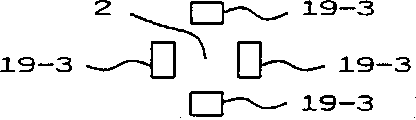
Fig. 4 A is a top schematic view, has shown the structure of the light receiving element among the embodiment of Fig. 1 and an example of setting;
Fig. 4 B is a top schematic view, has shown the structure of this light receiving element and another example of setting;
Fig. 4 C is a schematic top plan view, has shown the structure of this light receiving element and another example of setting;
Fig. 4 D is a schematic top plan view, has shown the structure of this light receiving element and another example of setting;
Fig. 5 is the schematic side cut-open view, has shown an example of the structure of the semiconductor laser part in another embodiment of the present invention;
Fig. 6 is the schematic side cut-open view, has shown an example of the structure of the semiconductor laser part in the another embodiment of the present invention; And
Fig. 7 is the schematic side cut-open view, has shown the structure of the optical system that adopts in the optical information recording of prior art and the replay device.
Referring to Fig. 1, one embodiment of the present of invention have wherein been shown, with identical parts among the representative of label identical among Fig. 7 and this figure.The optical arrangement of present embodiment is described earlier, be in from the center of the radiant light forward of semiconductor laser chip 1 output and non-peripheral light component 2 on every side thereof, by being formed on the center pit 21 on the light receiving element 19 and entering collimation lens 3, enter beam splitter 4 with the form of collimated light beam from collimation lens 3 these non-peripheral light components; Light receiving element 19 is such as annular.Beam splitter 4 can be a polarization beam apparatus that allows all incident lights to pass through.After this, with the top described similar mode of Fig. 7 that combines, from light receiving element 13 derived information signals, focus control signal and tracking control signal.
Fig. 2 shows the essential part of the embodiment of Fig. 1 in greater detail, particularly adopts a specific embodiment of the semiconductor laser part of semiconductor laser chip 1.Semiconductor laser chip 1 is contained in the shell 21, and the inside of shell 21 is held hermetic seal.Shell 21 has a Laser emission window 22 that is covered by transparent plate 23, and the light receiving element 19 of annular for example is preferably attached on the transparent plate 23.
Ring light receiving element 19 shown in Fig. 2 is attached in the side of transparent plate 23 in the face of semiconductor laser chip 1; Yet light receiving element 19 also can be attached in the opposite side of plate 23 and laser chip 1, as shown in Figure 3.
Novel structural characteristics of the present invention, be light receiving element 19 be set at Laser emission window 22 in the semiconductor laser chip 21 neighbouring or peripheral on, and the output of the light of element 19 is fed back to semiconductor laser instrument output control circuit 20.Promptly, in Fig. 2, be positioned at from the center or the non-peripheral light component 2 around it of the output of radiant light forward of semiconductor laser chip 1 output the center pit 22 of the light receiving element 19 by annular, enter collimation lens 3, and the peripheral light component of this radiant light enters light receiving element 19.In the case, peripheral light component 2 enters the number percent of collimation lens 3, depends on the NA (numerical aperture) of collimation lens 3.For example, if the NA of collimation lens 3 is chosen as 0.3 (NA=0.3)-often occur as institute in traditional optical information recording and playback system, the light component that is in 35 ° of three-dimensional radiation angles that the radiant light forward exported from semiconductor laser chip 1 exports can enter collimation lens 3.This correspondence is radiant light about 60% forward, and remaining 40% is comprised among the Zhou Bianguang 5 and by light receiving element 19 and receives.
Fig. 5 has shown another embodiment of the present invention, wherein is provided with mirror 24 and replaces light receiving element 19 in the foregoing description, and received by light receiving element 25 from the light of mirror 24 reflections.In this embodiment, the shape of mirror 24 and light receiving element 25 any one in can the element 19-1 to 19-4 as shown in Fig. 4 A to 4D.
Fig. 6 has shown another embodiment of the present invention, and wherein mirror 24 can be made up of concave mirror 26 except that level crossing.Adopt concave mirror 26 can be converged to reflected light single little luminous point, thereby can reduce the size of light receiving element 27 as far as possible from mirror 26.Therefore, can reduce the interelectrode capacitance of light receiving element 27 to greatest extent, thereby improve its APC response speed widely.
According to described the present invention, by a light receiving element obtained with from the corresponding light output of the peripheral light component of the radiant light forward of semi-conductor chip, and make its be fed to be controlled by semiconductor laser instrument output control circuit.Because this feature, the present invention can realize excellent result, and output power control promptly provided by the invention more than the no relevant feedback control that prior art provided of adopting radiant light backward effectively and can be adopted the beam splitter of any kind of.In addition, owing to can adopt undersized light receiving element, the response speed of this element can not reduce, thereby need not provide any device that the light that incides on the light receiving element is assembled of being used for, thereby can improve output power of laser control and APC response characteristic, elimination greatly to the restriction of designs and can reduce size of devices and cost greatly for preventing that this response speed from reducing.
Claims (9)
1. optical information recording and replay device comprise:
A semiconductor laser device;
A light receiving element is used to receive the Zhou Bianguang of the radiant light forward of the laser that described semiconductor laser device produces;
One optical system, the laser that is used to utilize described semiconductor laser device to produce record information on the optical information recording medium or from the optical information recording medium playback information.
It is characterized in that described light receiving element is set on the periphery of a Laser emission window, and this Laser emission window is set in the shell of described semiconductor laser device; Described Laser emission window is set up in order to launch the laser that is produced by described semiconductor laser device, and described Laser emission window comprises a transparent panel;
Control device is used for the output according to described light receiving element, controls the output power of laser that described semiconductor devices produces.
2. according to the optical information recording and the replay device of claim 1, it is characterized in that described light receiving element is set on the periphery of the described window that is positioned at described shell.
3. according to the optical information recording and the replay device of claim 1, it is characterized in that described window comprises a transparent panel, described light receiving element is set on the periphery of the described window that is positioned at described shell.
4. according to the optical information recording and the replay device of claim 1, it is characterized in that described window comprises a transparent panel, described light receiving element is set on the periphery that is positioned at the described window outside the described shell.
5. according to the optical information recording and the replay device of claim 1, it is characterized in that described light receiving element is arranged on the periphery of a window with loop configurations.
6. according to the optical information recording and the replay device of claim 1, it is characterized in that described light receiving element comprises a plurality of parts on the periphery that is arranged on a window.
7. according to the optical information recording and the replay device of claim 1, it is characterized in that, the periphery of the window that is provided with is provided with reflection unit in order to launch the laser that is produced by described semiconductor laser device, and the Zhou Bianguang of the radiant light forward of the laser that is produced by described semiconductor devices is reflected by described reflection unit and received by described light receiving element subsequently.
8. according to the optical information recording and the replay device of claim 7, it is characterized in that, described reflection unit comprises the level crossing on the periphery that is arranged on described window, and described light receiving element is set on the periphery of described semiconductor laser device to receive by the light of described mirror reflection.
9. according to the optical information recording and the replay device of claim 7, it is characterized in that described reflection unit comprises a concave mirror, and described light receiving element is set on the position that the light that reflected by described reflection unit assembles.
Applications Claiming Priority (3)
| Application Number | Priority Date | Filing Date | Title |
|---|---|---|---|
| JP5122028A JPH06309685A (en) | 1993-04-26 | 1993-04-26 | Laser output control device for optical information recording/reproducing device |
| JP122028/1993 | 1993-04-26 | ||
| JP122028/93 | 1993-04-26 |
Publications (2)
| Publication Number | Publication Date |
|---|---|
| CN1100550A CN1100550A (en) | 1995-03-22 |
| CN1056936C true CN1056936C (en) | 2000-09-27 |
Family
ID=14825809
Family Applications (1)
| Application Number | Title | Priority Date | Filing Date |
|---|---|---|---|
| CN94104667A Expired - Fee Related CN1056936C (en) | 1993-04-26 | 1994-04-25 | Laser output control device for an optical information recording and reproducing apparatus |
Country Status (8)
| Country | Link |
|---|---|
| US (1) | US5600621A (en) |
| EP (1) | EP0623922B1 (en) |
| JP (1) | JPH06309685A (en) |
| KR (1) | KR940024709A (en) |
| CN (1) | CN1056936C (en) |
| AU (1) | AU668464B2 (en) |
| DE (1) | DE69425090T2 (en) |
| TW (1) | TW253966B (en) |
Cited By (1)
| Publication number | Priority date | Publication date | Assignee | Title |
|---|---|---|---|---|
| CN100346400C (en) * | 2001-11-02 | 2007-10-31 | 日本胜利株式会社 | CD and its related device and method |
Families Citing this family (19)
| Publication number | Priority date | Publication date | Assignee | Title |
|---|---|---|---|---|
| DE29502016U1 (en) * | 1995-02-08 | 1995-03-30 | Linotype Hell Ag Werk Kiel | Optoelectronic recording device |
| KR100219141B1 (en) * | 1996-04-18 | 1999-09-01 | 윤종용 | Laser diode package having optical power monitoring function |
| JPH1065218A (en) * | 1996-08-23 | 1998-03-06 | Kdk Corp | Led for optical system |
| US5953355A (en) * | 1997-04-02 | 1999-09-14 | Motorola, Inc. | Semiconductor laser package with power monitoring system |
| JP3765348B2 (en) * | 1997-05-29 | 2006-04-12 | ミツミ電機株式会社 | Laser beam projector |
| JPH11273119A (en) * | 1998-03-24 | 1999-10-08 | Pioneer Electron Corp | Optical pickup device |
| JP3382846B2 (en) | 1998-05-11 | 2003-03-04 | 日本電気株式会社 | Optical head and method of monitoring light source output in optical head |
| US6674709B1 (en) * | 1999-04-23 | 2004-01-06 | Matsushita Electric Industrial Co., Ltd. | Optical head apparatus |
| JP2003060299A (en) * | 2001-06-07 | 2003-02-28 | Ricoh Opt Ind Co Ltd | Optical output device, optical output device array, lens device, and lens device array |
| JP4190775B2 (en) * | 2002-03-05 | 2008-12-03 | Necエレクトロニクス株式会社 | Wavelength stabilized semiconductor laser module |
| US7218591B2 (en) | 2002-04-17 | 2007-05-15 | Sharp Kabushiki Kaisha | Optical pickup apparatus |
| JP4645008B2 (en) | 2002-06-10 | 2011-03-09 | 日亜化学工業株式会社 | Semiconductor laser device |
| KR100498481B1 (en) * | 2003-01-24 | 2005-07-01 | 삼성전자주식회사 | Optical pickup apparatus |
| JP3866691B2 (en) * | 2003-07-01 | 2007-01-10 | シャープ株式会社 | Optical pickup device and optical disk device comprising the same |
| JP3991227B2 (en) | 2003-11-12 | 2007-10-17 | 船井電機株式会社 | Optical head device |
| US20070263683A1 (en) * | 2006-05-12 | 2007-11-15 | Canon Kabushiki Kaisha | Optical apparatus and image forming apparatus |
| JP5262231B2 (en) | 2008-03-27 | 2013-08-14 | セイコーエプソン株式会社 | Light source device and image display device |
| CN105572815B (en) * | 2015-12-21 | 2018-02-23 | 华进半导体封装先导技术研发中心有限公司 | Active optics pinboard and optical interconnection module |
| DE102017207224B4 (en) | 2017-04-28 | 2024-01-04 | pmdtechnologies ag | Illumination module with a surface emitter and a monitor receiver |
Citations (3)
| Publication number | Priority date | Publication date | Assignee | Title |
|---|---|---|---|---|
| JPS506260A (en) * | 1973-05-17 | 1975-01-22 | ||
| JPS60257584A (en) * | 1984-06-04 | 1985-12-19 | Sharp Corp | Photodetector built-in type semiconductor laser |
| EP0183569A2 (en) * | 1984-11-30 | 1986-06-04 | Sharp Kabushiki Kaisha | A semiconductor laser apparatus |
Family Cites Families (13)
| Publication number | Priority date | Publication date | Assignee | Title |
|---|---|---|---|---|
| JPS5410481B2 (en) * | 1974-09-06 | 1979-05-07 | ||
| JPS5223902A (en) * | 1975-08-18 | 1977-02-23 | Matsushita Electric Ind Co Ltd | Optical playback device |
| CA1258906A (en) * | 1985-04-22 | 1989-08-29 | Hiroshi Oinoue | Semiconductor laser apparatus for optical head |
| DE3680865D1 (en) * | 1985-11-11 | 1991-09-19 | Sharp Kk | OPTICAL HEAD. |
| JPH0614570B2 (en) * | 1987-04-28 | 1994-02-23 | シャープ株式会社 | Optical output stabilizing method and photodetector used in the method |
| JPH0247015A (en) * | 1988-08-10 | 1990-02-16 | Nippon Zeon Co Ltd | Manufacture of material with gradient function |
| JPH0296622U (en) * | 1989-01-18 | 1990-08-01 | ||
| JPH0778904B2 (en) * | 1989-01-27 | 1995-08-23 | シャープ株式会社 | Optical pickup device |
| US5023858A (en) * | 1989-02-28 | 1991-06-11 | Ricoh Company, Ltd. | Separation type optical pickup device |
| JPH04330646A (en) * | 1991-05-01 | 1992-11-18 | Nippon Conlux Co Ltd | Laser output controller for optical information recording/reproducing device |
| JPH056260A (en) * | 1991-06-27 | 1993-01-14 | Nec Corp | Japanese data compressing system |
| US5191204A (en) * | 1991-10-28 | 1993-03-02 | International Business Machines Corporation | Multi-beam optical system and method with power detection of overlapping beams |
| JPH05128569A (en) * | 1991-10-31 | 1993-05-25 | Mitsubishi Electric Corp | Optical pickup apparatus |
-
1993
- 1993-04-26 JP JP5122028A patent/JPH06309685A/en active Pending
-
1994
- 1994-04-15 TW TW083103349A patent/TW253966B/zh active
- 1994-04-20 EP EP94106095A patent/EP0623922B1/en not_active Expired - Lifetime
- 1994-04-20 DE DE69425090T patent/DE69425090T2/en not_active Expired - Fee Related
- 1994-04-20 KR KR1019940008299A patent/KR940024709A/en not_active Application Discontinuation
- 1994-04-21 US US08/230,593 patent/US5600621A/en not_active Expired - Fee Related
- 1994-04-25 CN CN94104667A patent/CN1056936C/en not_active Expired - Fee Related
- 1994-04-26 AU AU60692/94A patent/AU668464B2/en not_active Ceased
Patent Citations (3)
| Publication number | Priority date | Publication date | Assignee | Title |
|---|---|---|---|---|
| JPS506260A (en) * | 1973-05-17 | 1975-01-22 | ||
| JPS60257584A (en) * | 1984-06-04 | 1985-12-19 | Sharp Corp | Photodetector built-in type semiconductor laser |
| EP0183569A2 (en) * | 1984-11-30 | 1986-06-04 | Sharp Kabushiki Kaisha | A semiconductor laser apparatus |
Cited By (1)
| Publication number | Priority date | Publication date | Assignee | Title |
|---|---|---|---|---|
| CN100346400C (en) * | 2001-11-02 | 2007-10-31 | 日本胜利株式会社 | CD and its related device and method |
Also Published As
| Publication number | Publication date |
|---|---|
| AU6069294A (en) | 1994-11-03 |
| TW253966B (en) | 1995-08-11 |
| US5600621A (en) | 1997-02-04 |
| JPH06309685A (en) | 1994-11-04 |
| AU668464B2 (en) | 1996-05-02 |
| CN1100550A (en) | 1995-03-22 |
| DE69425090D1 (en) | 2000-08-10 |
| EP0623922A1 (en) | 1994-11-09 |
| EP0623922B1 (en) | 2000-07-05 |
| DE69425090T2 (en) | 2001-03-01 |
| KR940024709A (en) | 1994-11-18 |
Similar Documents
| Publication | Publication Date | Title |
|---|---|---|
| CN1056936C (en) | Laser output control device for an optical information recording and reproducing apparatus | |
| US5247167A (en) | Multiple beam power monitoring system and method with radiation detection and focusing means of overlapping beams | |
| CN1094230C (en) | Optical pickup | |
| US5787058A (en) | Optical pickup apparatus utilizing a polygonal prism | |
| CN1158478A (en) | Reproducing and recording optical pickup compatible for discs having different thicknesses | |
| CN1181576A (en) | Optical pickup device with plurality of laser couplers | |
| JPH04360041A (en) | Optical type disk and pickup device | |
| US5107101A (en) | Optical information processing apparatus with peak hold circuit for gain control signal | |
| US5748602A (en) | Single-lens optical pick-up head for accessing a DVD disc and a CD disc by switching between two optical states | |
| US6396790B2 (en) | Optical head and information recording and reproducing apparatus using it | |
| EP0207164B1 (en) | Apparatus for recording and reproducing optical recording card | |
| CA2002381A1 (en) | Optical pickup device | |
| EP0311463A2 (en) | An optical information reproducing apparatus | |
| CN1312681C (en) | Optical head and optical disc device | |
| US4588263A (en) | An adjustable-optical prism with integral-polarizing beam splitter and applications thereof | |
| CN1088885C (en) | Laser diode elements with light yield mornitoring function | |
| CN100524483C (en) | Optical pickup device, optical disc device and prism | |
| CN1110040C (en) | Optical pickup | |
| KR100712330B1 (en) | Optical pick up having a tracking coil which is designed slopely | |
| JPH02189733A (en) | Optical head | |
| KR970000083Y1 (en) | Scanning apparatus | |
| JPH0547000A (en) | Optical head structure | |
| KR970002940Y1 (en) | Optical pick-up for optical disk player | |
| CN1229237A (en) | Optical pickup for narrow track optical discs | |
| EP0392852A2 (en) | An optical head |
Legal Events
| Date | Code | Title | Description |
|---|---|---|---|
| C10 | Entry into substantive examination | ||
| SE01 | Entry into force of request for substantive examination | ||
| C06 | Publication | ||
| PB01 | Publication | ||
| C10 | Entry into substantive examination | ||
| SE01 | Entry into force of request for substantive examination | ||
| C10 | Entry into substantive examination | ||
| SE01 | Entry into force of request for substantive examination | ||
| C14 | Grant of patent or utility model | ||
| GR01 | Patent grant | ||
| C19 | Lapse of patent right due to non-payment of the annual fee | ||
| CF01 | Termination of patent right due to non-payment of annual fee |