CN105684534B - Method and apparatus for performing downlink MU-MIMO transmission - Google Patents
Method and apparatus for performing downlink MU-MIMO transmission Download PDFInfo
- Publication number
- CN105684534B CN105684534B CN201380079027.8A CN201380079027A CN105684534B CN 105684534 B CN105684534 B CN 105684534B CN 201380079027 A CN201380079027 A CN 201380079027A CN 105684534 B CN105684534 B CN 105684534B
- Authority
- CN
- China
- Prior art keywords
- layer
- transmission
- ues
- scheduled
- real
- Prior art date
- Legal status (The legal status is an assumption and is not a legal conclusion. Google has not performed a legal analysis and makes no representation as to the accuracy of the status listed.)
- Expired - Fee Related
Links
- 230000005540 biological transmission Effects 0.000 title claims abstract description 159
- 238000000034 method Methods 0.000 title claims abstract description 29
- 238000004891 communication Methods 0.000 claims abstract description 30
- 238000001514 detection method Methods 0.000 claims description 21
- 230000007774 longterm Effects 0.000 claims description 9
- 238000000794 confocal Raman spectroscopy Methods 0.000 claims description 7
- 238000011500 cytoreductive surgery Methods 0.000 claims description 7
- 230000001960 triggered effect Effects 0.000 claims description 6
- 230000007246 mechanism Effects 0.000 claims description 5
- 101000741965 Homo sapiens Inactive tyrosine-protein kinase PRAG1 Proteins 0.000 claims 6
- 102100038659 Inactive tyrosine-protein kinase PRAG1 Human genes 0.000 claims 6
- 238000013507 mapping Methods 0.000 claims 1
- 239000010410 layer Substances 0.000 description 300
- 239000011229 interlayer Substances 0.000 description 13
- 238000010586 diagram Methods 0.000 description 12
- 108010076504 Protein Sorting Signals Proteins 0.000 description 10
- 239000011159 matrix material Substances 0.000 description 9
- 238000005516 engineering process Methods 0.000 description 8
- 238000000926 separation method Methods 0.000 description 7
- 239000002356 single layer Substances 0.000 description 7
- 238000012545 processing Methods 0.000 description 6
- 230000000116 mitigating effect Effects 0.000 description 5
- 238000004590 computer program Methods 0.000 description 4
- 101150071746 Pbsn gene Proteins 0.000 description 3
- 230000015556 catabolic process Effects 0.000 description 3
- 238000006731 degradation reaction Methods 0.000 description 3
- 230000000153 supplemental effect Effects 0.000 description 3
- 238000012360 testing method Methods 0.000 description 3
- 230000000694 effects Effects 0.000 description 2
- 230000006870 function Effects 0.000 description 2
- GVVPGTZRZFNKDS-JXMROGBWSA-N geranyl diphosphate Chemical compound CC(C)=CCC\C(C)=C\CO[P@](O)(=O)OP(O)(O)=O GVVPGTZRZFNKDS-JXMROGBWSA-N 0.000 description 2
- 230000002452 interceptive effect Effects 0.000 description 2
- 238000012986 modification Methods 0.000 description 2
- 230000004048 modification Effects 0.000 description 2
- 230000006399 behavior Effects 0.000 description 1
- 230000001413 cellular effect Effects 0.000 description 1
- 230000001360 synchronised effect Effects 0.000 description 1
Images


Classifications
-
- H—ELECTRICITY
- H04—ELECTRIC COMMUNICATION TECHNIQUE
- H04W—WIRELESS COMMUNICATION NETWORKS
- H04W72/00—Local resource management
- H04W72/20—Control channels or signalling for resource management
-
- H—ELECTRICITY
- H04—ELECTRIC COMMUNICATION TECHNIQUE
- H04B—TRANSMISSION
- H04B7/00—Radio transmission systems, i.e. using radiation field
- H04B7/02—Diversity systems; Multi-antenna system, i.e. transmission or reception using multiple antennas
- H04B7/04—Diversity systems; Multi-antenna system, i.e. transmission or reception using multiple antennas using two or more spaced independent antennas
- H04B7/0413—MIMO systems
- H04B7/0452—Multi-user MIMO systems
-
- H—ELECTRICITY
- H04—ELECTRIC COMMUNICATION TECHNIQUE
- H04B—TRANSMISSION
- H04B7/00—Radio transmission systems, i.e. using radiation field
- H04B7/02—Diversity systems; Multi-antenna system, i.e. transmission or reception using multiple antennas
- H04B7/04—Diversity systems; Multi-antenna system, i.e. transmission or reception using multiple antennas using two or more spaced independent antennas
- H04B7/0413—MIMO systems
- H04B7/0456—Selection of precoding matrices or codebooks, e.g. using matrices antenna weighting
-
- H—ELECTRICITY
- H04—ELECTRIC COMMUNICATION TECHNIQUE
- H04J—MULTIPLEX COMMUNICATION
- H04J11/00—Orthogonal multiplex systems, e.g. using WALSH codes
- H04J11/0023—Interference mitigation or co-ordination
- H04J11/0026—Interference mitigation or co-ordination of multi-user interference
- H04J11/0036—Interference mitigation or co-ordination of multi-user interference at the receiver
-
- H—ELECTRICITY
- H04—ELECTRIC COMMUNICATION TECHNIQUE
- H04L—TRANSMISSION OF DIGITAL INFORMATION, e.g. TELEGRAPHIC COMMUNICATION
- H04L1/00—Arrangements for detecting or preventing errors in the information received
- H04L1/12—Arrangements for detecting or preventing errors in the information received by using return channel
- H04L1/16—Arrangements for detecting or preventing errors in the information received by using return channel in which the return channel carries supervisory signals, e.g. repetition request signals
- H04L1/1607—Details of the supervisory signal
-
- H—ELECTRICITY
- H04—ELECTRIC COMMUNICATION TECHNIQUE
- H04L—TRANSMISSION OF DIGITAL INFORMATION, e.g. TELEGRAPHIC COMMUNICATION
- H04L1/00—Arrangements for detecting or preventing errors in the information received
- H04L1/12—Arrangements for detecting or preventing errors in the information received by using return channel
- H04L1/16—Arrangements for detecting or preventing errors in the information received by using return channel in which the return channel carries supervisory signals, e.g. repetition request signals
- H04L1/18—Automatic repetition systems, e.g. Van Duuren systems
- H04L1/1829—Arrangements specially adapted for the receiver end
- H04L1/1861—Physical mapping arrangements
-
- H—ELECTRICITY
- H04—ELECTRIC COMMUNICATION TECHNIQUE
- H04L—TRANSMISSION OF DIGITAL INFORMATION, e.g. TELEGRAPHIC COMMUNICATION
- H04L25/00—Baseband systems
- H04L25/02—Details ; arrangements for supplying electrical power along data transmission lines
- H04L25/03—Shaping networks in transmitter or receiver, e.g. adaptive shaping networks
- H04L25/03891—Spatial equalizers
- H04L25/03898—Spatial equalizers codebook-based design
-
- H—ELECTRICITY
- H04—ELECTRIC COMMUNICATION TECHNIQUE
- H04L—TRANSMISSION OF DIGITAL INFORMATION, e.g. TELEGRAPHIC COMMUNICATION
- H04L5/00—Arrangements affording multiple use of the transmission path
- H04L5/14—Two-way operation using the same type of signal, i.e. duplex
-
- H—ELECTRICITY
- H04—ELECTRIC COMMUNICATION TECHNIQUE
- H04W—WIRELESS COMMUNICATION NETWORKS
- H04W72/00—Local resource management
- H04W72/12—Wireless traffic scheduling
- H04W72/1263—Mapping of traffic onto schedule, e.g. scheduled allocation or multiplexing of flows
- H04W72/1273—Mapping of traffic onto schedule, e.g. scheduled allocation or multiplexing of flows of downlink data flows
-
- H—ELECTRICITY
- H04—ELECTRIC COMMUNICATION TECHNIQUE
- H04L—TRANSMISSION OF DIGITAL INFORMATION, e.g. TELEGRAPHIC COMMUNICATION
- H04L25/00—Baseband systems
- H04L25/02—Details ; arrangements for supplying electrical power along data transmission lines
- H04L25/0202—Channel estimation
- H04L25/0224—Channel estimation using sounding signals
- H04L25/0228—Channel estimation using sounding signals with direct estimation from sounding signals
Landscapes
- Engineering & Computer Science (AREA)
- Signal Processing (AREA)
- Computer Networks & Wireless Communication (AREA)
- Physics & Mathematics (AREA)
- Mathematical Physics (AREA)
- Power Engineering (AREA)
- Mobile Radio Communication Systems (AREA)
- Radio Transmission System (AREA)
Abstract
Embodiments disclose methods and devices for performing DL MU-MIMO transmission in a radio communication network implementing MU-MIMO. The method comprises the following steps: pairing the UE with one or more other UEs for DL MU-MIMO transmission in the radio communication network; scheduling at least one real layer and at least one virtual layer to the UE over a control channel, wherein each of the at least one virtual layer is a real layer scheduled for at least one of the one or more other UEs; and performing DL transmissions to the UE and one or more other UEs on the transport channel, wherein only the at least one real layer is used for DL transmissions to the UE and each of the at least one virtual layer is used for DL transmissions to at least one of the one or more other UEs.
Description
Technical Field
The present technology relates to the field of radio communications, and in particular, to a method of performing Downlink (DL) multi-user multiple-input multiple-output (MU-MIMO) transmission. The technology also relates to an apparatus and a computer-readable storage medium for performing the method.
Background
In systems implementing MIMO technology, such as Long Term Evolution (LTE) systems, MIMO technology helps to improve frequency efficiency and network capacity in the third generation partnership project (3 GPP). For example, in (TM) 3, TM4, and TM8 of transmission mode version 9, two-layer transmission is scheduled for a single user as single-user MIMO (SU-MIMO). Alternatively, two or more User Equipments (UEs) may be paired together to share the same time-frequency resources as MU-MIMO. MU-MIMO further employs spatial separation and diversity and higher frequency efficiency than expected for SU-MIMO, however this may not be the case in practice.
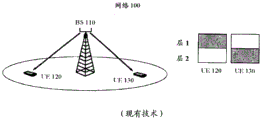
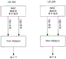
Due to limitations of the antennas and processing capabilities of the UEs, a typical scenario for MU-MIMO is to schedule partial layers to each of the paired UEs. The remaining layers are disabled because dummy for other paired UEs. Taking single-layer DL MU-MIMO as an example, two layers are available for two UEs. Typically, only one layer is scheduled for each of the paired UEs, as shown in fig. 1.
In conventional MU-MIMO, each UE suffers from strong inter-layer interference from other paired UEs, since the paired UEs are not well separated from each other. In general, in contrast to SU-MIMO using joint detection (e.g., Minimum Mean Square Estimation (MMSE) or Interference Rejection Combining (IRC) receiver), interference from paired UEs is simply seen as noise in MU-MIMO without Joint Detection (JD) as in SU-MIMO, which results in the throughput degradation observed in field testing.
In order to improve MU-MIMO performance, several solutions have been proposed:
1) paired UE with good spatial separation
The problem is that spatial separation in DL is difficult to estimate by enodeb (enb). And the pairing rate will be degraded in order to obtain a good multi-user separation. Thus, the presence of interference and low pairing rates limit performance gain.
2) Designing null beamforming weights
The weight of the paired UE may be carefully designed to clear interference. However, the weights are calculated based on Uplink (UL) channel estimates. Due to channel estimation inaccuracy and non-ideal channel reciprocity, it is difficult for the eNB to separate such DL inter-layer interference well.
On the other hand, when null beamforming weights are used, the power of the desired signal is degraded compared to the Minimum Ratio Combining (MRC) and beam-rate-Grid (GOB) weights. Furthermore, the computational complexity of the headroom process is another challenge for the eNB.
3) Blind IRC on UE side
Some advanced UEs have the ability to perform blind IRC to mitigate unknown interference. However, it does not solve inter-layer interference well in DL MU-MIMO, but for other reasons, not all UEs support blind IRC in any case. The receiver algorithm is a UE specific behavior, which is not mandatory by 3 GPP. Due to complex processing, various scenarios, etc., it may not be possible that all UE vendors support or enable IRC in any case. Thus, when DL MU-MIMO is performed, it cannot be assumed that IRC works well on the UE side.
4) Blind detection in the presence of interference layers
As specified in 3GPP and described in patent application No. US20100285810, the UE-specific reference signals of port 7, port 8 and port v +6 are independent of the UE-specific Radio Network Temporary Identifier (RNTI) and length of the allocated Physical Resource Block (PRB). This allows the UE to blindly detect if other layers are scheduled simultaneously for other UEs and channel estimation of MMSE or IRC accordingly. It requires the UE to perform blind detection by searching all possible reference sequences when there is interference on each PRB. It introduces additional complexity for the UE. Furthermore, such blind detection is not robust enough, with the possibility of false alarms or dropouts, due to imperfect orthogonality of the interfering sequences. Furthermore, in Common Reference Signal (CRS) based transmission modes (e.g., TM 4), blind detection is not feasible in the presence of an interfering layer.
Disclosure of Invention
An aspect of the present disclosure is to perform a method of DL MU-MIMO transmission in a base station of a radio communication network implementing MU-MIMO. The method comprises the following steps: pairing the UE with one or more other UEs for dl mu-MIMO transmission in the radio communication network; scheduling at least one real layer and at least one virtual layer to the UE over a control channel, wherein each of the at least one virtual layer is a real layer scheduled for at least one of the one or more other UEs; and performing DL transmissions to the UE and the one or more other UEs on a transport channel, wherein only the at least one real layer is used for DL transmissions to the UE and each of the at least one virtual layer is used for DL transmissions to at least one UE of the one or more other UEs.
Another aspect of the present disclosure is a base station configured to perform DL MU-MIMO transmission in a radio communication network implementing MU-MIMO. The base station may include a pairing unit, a scheduling unit, and an execution unit. A pairing unit adapted to pair a UE with one or more other UEs for DL MU-MIMO transmission in the radio communication network; a scheduling unit adapted to schedule at least one real layer and at least one virtual layer to the UE over a control channel, wherein each of the at least one virtual layer is a real layer scheduled for at least one of the one or more other UEs; and an execution unit adapted to perform DL transmissions to the UE and the one or more other UEs on a transport channel, wherein only the at least one real layer is used for DL transmissions to the UE and each of the at least one virtual layer is used for DL transmissions to at least one UE of the one or more other UEs.
Yet another aspect of the disclosure is a computer readable storage medium storing instructions that, when executed on a base station, cause the base station to perform the method steps described above.
Yet another aspect of the present disclosure is an apparatus for performing DL transmission in a radio communication network implementing MU-MIMO. The apparatus may include a processor and a memory. The memory contains instructions executable by the processor whereby the apparatus is operative to: pairing the UE with one or more other UEs for DL MU-MIMO transmission in the radio communication network; scheduling at least one real layer and at least one virtual layer to the UE over a control channel, wherein each of the at least one virtual layer is a real layer scheduled for at least one of the one or more other UEs; and performing DL transmissions to the UE and the one or more other UEs on a transport channel, wherein only the at least one real layer is used for DL transmissions to the UE and each of the at least one virtual layer is used for DL transmissions to at least one UE of the one or more other UEs.
When a UE of the paired UEs is scheduled with a real layer for its own DL transmission and a virtual layer actually used for other paired UEs for such DL transmission, the UE is implicitly triggered to perform joint detection between all scheduled layers including the real layer and the virtual layer, and at the same time may be provided with supplemental information that may be used in the joint detection, such as scrambling identity of reference signals, precoding matrix, layer number, etc. Thus, interference from the virtual layer (i.e., inter-layer interference from other paired UEs) may be mitigated or even removed by the UE in a non-blind manner. With inter-layer interference mitigation/removal between paired UEs in DL MU-MIMO transmission, performance gains of MU-MIMO over SU-MIMO can be easily achieved by further exploiting spatial separation and diversity.
Drawings
The technology will now be described, by way of example only, with reference to the accompanying drawings, in which:
fig. 1 illustrates a schematic diagram of a conventional DL MU-MIMO transmission in a radio communication network;
fig. 2 illustrates a schematic diagram of DL MU-MIMO transmission according to an embodiment in a radio communication network;
fig. 3 schematically illustrates a flow chart for performing DL MU-MIMO transmission according to an embodiment;
fig. 4a illustrates a schematic diagram of DL MU-MIMO scheduling on a control channel according to an embodiment;
fig. 4b illustrates a schematic diagram of DL MU-MIMO scheduling on a transmission channel according to an embodiment;
fig. 5a schematically illustrates a paired UE with fully overlapping PRB allocation on each layer, according to an embodiment;
fig. 5b schematically illustrates a paired UE allocated with partially overlapping PRBs according to an embodiment;
figure 6 illustrates a schematic diagram of a combined cell suitable for implementing embodiments; and
fig. 7 schematically illustrates a block diagram of a base station configured to perform DL MI-MIMO transmission according to an embodiment.
Detailed Description
Embodiments herein will be described more fully hereinafter with reference to the accompanying drawings. The embodiments herein may, however, be embodied in many different forms and should not be construed as limiting the scope of the appended claims. The elements of the drawings are not necessarily to scale relative to each other. Like numbers refer to like elements throughout.
The terminology used herein is for the purpose of describing particular embodiments only and is not intended to be limiting. As used herein, the singular forms "a", "an" and "the" are intended to include the plural forms as well, unless the context clearly indicates otherwise. It will be further understood that the terms "comprises" and/or "comprising," when used herein, specify the presence of stated features, integers, steps, operations, elements, and/or components, but do not preclude the presence or addition of one or more other features, integers, steps, operations, elements, components, and/or groups thereof.
Unless otherwise defined, all terms (including technical and scientific terms) used herein have the same meaning as commonly understood. It will be further understood that terms used herein should be interpreted as having a meaning that is consistent with their meaning in the context of this specification and the relevant art and will not be interpreted in an idealized or overly formal sense unless expressly so defined herein.
The present technology is described below with reference to block diagrams and/or flowchart illustrations of methods, apparatus (systems) and/or computer programs in accordance with the present embodiments. It will be understood that each block of the block diagrams and/or flowchart illustrations, and combinations of blocks in the block diagrams and/or flowchart illustrations, can be implemented by computer program instructions. These computer program instructions may be provided to a processor, controller or control unit of a general purpose computer, special purpose computer, and/or other programmable data processing apparatus to produce a machine, such that the instructions, which execute via the processor of the computer and/or other programmable data processing apparatus, create means for implementing the functions/acts specified in the block diagrams and/or flowchart block or blocks.
Accordingly, the present techniques may be embodied in hardware and/or in software (including firmware, resident software, micro-code, etc.). Furthermore, the techniques may take the form of a computer program on a computer-usable or computer-readable storage medium having computer-usable or computer-readable program code embodied in the medium for use by or in connection with an instruction execution system. In the context of this document, a computer-usable or computer-readable storage medium may be any medium that can contain, store, or be suitable for communicating the program for use by or in connection with the instruction execution system, apparatus, or device.
Although specific terms in some specifications, such as base station, are used herein, it should be understood that embodiments are not limited to those specific terms, but are applicable to all such entities, such as Access Points (APs), cells, sectors, femto base stations, Core Networks (CNs), nodebs, enodebs, etc.
Embodiments herein will be described below with reference to the accompanying drawings.
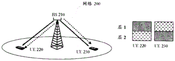
Fig. 2 illustrates a schematic diagram of DL MU-MIMO transmission according to an embodiment in a radio communication network.
As shown in fig. 2, the network 20 includes a Base Station (BS) 210. BS210 serves UE220 and UE 230. Here, the network 200 may refer to any radio communication network implementing MU-MIMO mechanisms, including but not limited to time division duplex long term evolution (TDD-LTE), frequency division duplex long term evolution (FDD-LTE), time division synchronous code division multiple access (TD-SCDMA), wireless fidelity (WiFi), bluetooth, Universal Mobile Telecommunications System (UMTS), Worldwide Interoperability for Microwave Access (WiMAX), and so forth. The term "base station" as used herein may indicate any type of communication node, such as an Access Point (AP), macro base station, femto base station, Core Network (CN), NodeB, eNodeB, etc. For simplicity, embodiments will be described in the context of an LTE system. The term "UE" as used herein may refer to all forms of devices that enable a user to communicate via a radio communication network, such as smart phones, cellular phones, Personal Digital Assistants (PDAs), and the like.
For simplicity and clarity, only one BS and two UEs are shown in the radio communication network 200. It will be appreciated that one or more BSs may be present in a wireless communication network, and that each BS may serve one or more UEs simultaneously.
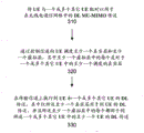
The procedure of the embodiments will now be described in detail with reference to fig. 2 and the flowchart illustrated in fig. 3, fig. 3 showing a method of performing DL MU-MIMO transmission according to the embodiments.
At block 310, BS210 pairs a UE (e.g., UE 220) with one or more other UEs (e.g., UE 230) for DL MU-MIMO transmission in a radio communication network (e.g., network 200). DL transmission refers to data transmission from the BS to the UE. Herein, the term "paired UE" will be used to denote two or more UEs sharing the same time-frequency resources, e.g. at different layers of space, in a DL MU-MIMO transmission. For example, the paired UEs may include UE220 and UE 230. Here, it should be appreciated that more than one UE may be paired with a UE (e.g., UE220 or 230) for DL MU-MIMO transmission.
Specifically, the BS210 may pair UEs having a predetermined spatial distance from each other. However, it should be appreciated that BS210 may determine which UEs will be paired together for DL MU-MIMO transmission according to other known criteria.
At block 320, BS210 schedules at least one real layer and at least one virtual layer to a UE (e.g., UE 220) over a control channel (e.g., a Physical Downlink Control Channel (PDCCH)), and each of the at least one virtual layer is a real layer scheduled for at least one of one or more other UEs (e.g., UE230 in the case of fig. 2). Here, the real layer is defined as a layer scheduled to the UE through the control channel and used to perform DL transmission for the UE on the transport channel, and the virtual layer is defined as a layer scheduled to the UE through the control channel but not performing DL transmission for the UE on the transport channel. Indeed, in this embodiment, the virtual layer is used to perform DL transmissions to other UEs whose real layer is such a virtual layer. As indicated, only a partial layer scheduled to a UE will be charged with DL transmissions to such UE.
For example, BS210 may schedule layer 1 and layer 2 to UE220 through the PDCCH. Layer 1 serves as the real layer scheduling for UE220 and layer 2 serves as the virtual layer scheduling for UE 220. Meanwhile, BS210 schedules layer 2 to UE 230. Layer 2 is taken as the true layer scheduling for UE 230. Alternatively, BS210 may also schedule layer 1 and layer 2 to UE 230. In this case, layer 2 is still the real layer of UE230, while layer 1 is scheduled as the virtual layer of UE 230.
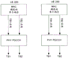
During scheduling, BS210 may allocate time-frequency resources for scheduled layers including real layers and virtual layers. In one embodiment, BS210 will allocate PRB resources and Modulation Coding Schemes (MCSs) according to the channel quality of UE220 for the real layer (i.e., layer 1) of UE220, as in conventional single-layer MU-MIMO, and at the same time, to implement the virtual layer (i.e., layer 2) of UE220, BS210 will also set DL assignment information for the corresponding Transport Blocks (TBs) in downlink control channel information (DCI). Finally, the DCI will be transmitted to the UE220 through the PDCCH. As a result, UE220 will assume TB1 and TB2 are enabled, as illustrated in fig. 4 a. Generally, TB may comprise one or more layers. For simplicity, in this example TB1 contains only layer 1 and TB2 contains only layer 2. In other words, in UE220 TB1 represents a real layer and TB2 represents a virtual layer, but in UE230 TB1 represents a virtual layer and TB2 represents a real layer.
It should be understood that in the case where there are multiple virtual layers available, the virtual layer of the UE may be selected as desired. For example, if there are three UEs paired together, i.e., UE a, UE B, and UE C, then layer 1 scheduled to UE a is its real layer, layer 2 scheduled to UE B is its real layer, and layer 3 scheduled to UE C is its real layer. As for UE a, the BS may schedule layer 2 and layer 3 to UE a as its virtual layer. Alternatively, the BS may only schedule layer 2 or layer 3 to UE a as its virtual layer.
Further, it should be appreciated that one or more layers may be scheduled to the UE as its real layers. For example, in one embodiment, if there are three layers and two UEs-UE a and UE B paired together, layer 1 and layer 2 scheduled to UE a may be their real layers, and layer 3 scheduled to UE B may be their real layers, while layer 3 also scheduled to UE a is its virtual layer.
Also, it should be appreciated that neither the real layer nor the virtual layer need be specifically scheduled to one UE. In other words, it is not necessary that all time-frequency resources on a single layer will be scheduled to one UE. Two or more UEs may share the same layer, on which different portions of the time-frequency resources are assigned.
At block 330, BS210 performs DL transmissions on a transport channel (e.g., a Physical Downlink Shared Channel (PDSCH)) to a UE (e.g., UE 220) and one or more other UEs (e.g., UE 230). As for the UE (e.g., 220), only the at least one real layer scheduled to itself is used for DL transmission to the UE, while each of the at least one virtual layer scheduled to the UE is used for DL transmission to at least one of the one or more other UEs.
For example, in the scenario shown in fig. 2, UE220 is scheduled with layer 1 as its real layer and layer 2 as its virtual layer, while UE230 is scheduled with layer 2 as its real layer and layer 1 as its virtual layer. In this case, the BS210 will only enable the real layer of each UE to DL transmit in the transport channel to the corresponding UE. Specifically, only layer 1 is used for transmission by PDSCH to UE220, and only layer 2 is used for transmission to UE 230. The virtual layer granted on the PDCCH is not actually used for transmission of the corresponding UE on the PDSCH. As illustrated in fig. 4b, for UE220, TB2 corresponding to layer 2 (the virtual layer of UE 220) is disabled, and for UE230, TB1 corresponding to layer 1 (the virtual layer of UE 230) is disabled.
When a UE of the paired UEs is scheduled with a real layer for its own DL transmission and a virtual layer actually used for other paired UEs for such DL transmission, the UE is implicitly triggered to perform joint detection between all scheduled layers including the real layer and the virtual layer, and at the same time may be provided with supplemental information that may be used in the joint detection, such as scrambling identity of reference signals, precoding matrix, layer number, etc. Thus, interference from the virtual layer (i.e., inter-layer interference from other paired UEs) may be mitigated or even removed by the UE in a non-blind manner. With inter-layer interference mitigation/removal between paired UEs in DL MU-MIMO transmission, performance gains of MU-MIMO over SU-MIMO can be easily achieved by further exploiting spatial separation and diversity. At the same time, due to the implementation of the embodiments, some disadvantages caused by conventional solutions, such as the problem of computational complexity of empty spatial processing, may be excluded.
As described above, the virtual layer scheduled to a UE (e.g., UE 220) will not be used to transmit payload data of this UE, but rather such virtual layer is used to transmit payload data of other UEs (e.g., UE 230) paired with this UE, thus also scheduling the virtual layer of this UE to other UEs as a real layer. However, the UE220 itself has no idea of distinguishing between the real layer and the virtual layer scheduled to it, and therefore the UE220 assumes that the layers scheduled to it (including the real layer and the virtual layer) will be used to transmit its payload data. In other words, the UE220 assumes all scheduled layers as its real layer. In this case, during DL MU-MIMO transmission, the UE220 will attempt to demodulate the data transmitted on the real and virtual layers. As expected, it can successfully demodulate data on the real layer and fail on the virtual layer. Due to the failure on the virtual layer, the UE220 will report a hybrid automatic repeat request (HARQ) Negative Acknowledgement (NACK) to the BS 210. According to an embodiment, after receiving such HARQ NACK feedback from the UE220, the BS210 may simply ignore it. In this way, the entire DL transmission process can operate as usual despite the additional virtual layer scheduling.
Further, it should be appreciated that the embodiments may be applicable to various networks having different antenna configurations (such as 2Tx, 4Tx, and 8 Tx) and transmission modes (such as TM3, TM4, TM8, and TM 9).
If the network's transmit mode (e.g., TM 4) requires codebook-based precoding, the BS (e.g., BS 210) may first determine the codebook for the UE (e.g., UE 220) based on the layer number scheduled for the UE and the codebook used in each scheduled layer. The UE uses the codebook for each real layer, while at least one of the one or more other UEs (e.g., UE 230) uses the codebook for each virtual layer. Then, the BS210 may inform the UE220 of the codebook.
For example, as shown in fig. 2, layer 1 is scheduled to UE220 as its real layer and to UE230 as its virtual layer, while layer 2 is scheduled to layer 230 as its real layer and to UE220 as its virtual layer. In general, each layer will use a respective codebook in the DL transmission. Since only a single layer (layer 1) is used to perform DL transmission to the UE220, the BS210 may refer toCodebooks to be used in its real layer (layer 1) For DL transmission, also, BS210 may also assign a codebook to be used on the real layer (layer 2) of UE230
 For DL transmission. Taking UE220 as an example, normally, if UE220 does not use virtual layer scheduling, BS210 may simply inform UE220 of the codebook used by UE220
 . However, the UE220 now schedules two layers, one real layer (layer 1) and one virtual layer (layer 2). As is known, joint detection between two scheduled layers involves a codebook (also called precoding matrix) used on each layer. To ensure effective joint detection at the UE220 side, BS210 will find a codebook that combines codebooks used on all layers (i.e.,
 layer 1 and layer 2) scheduled to UE220, and therefore BS210 may locate the codebook The results are shown in the following table. Finally, the BS210 informs the UE220 of the codebook
 Rather than of
 。
。

As observed in field testing, in TM4, the gain and channel quality on layer 1 and layer 2 are typically imbalanced, which leads to throughput degradation. Now, by implementing the above embodiments, imbalance can be applied. For example, for the UE220, the gain on layer 1 is much higher than the gain on layer 2. While for UE230, the gain on layer 2 is much higher than the gain on layer 1. As a result, gain from layer imbalance may be employed.
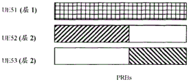
Alternatively, in a DL channel estimation Common Reference Signal (CRS) based transmission mode (e.g., TM 4), the physical resource block allocations on all layers scheduled for the UE completely overlap each other. For example, in TM4, DL channel estimation is performed using CRS and a precoding matrix. It allows two or more UEs to be paired together using the same precoding matrix. In other words, two or more UEs may share the same layer on which different portions of PRB resources are assigned. In this case, the combined PRB allocations on each layer will overlap strictly. As illustrated in fig. 5a, UE 51 occupies the PRB resources allocated on layer 1, while UE 52 and UE53 occupy different portions of the PRB resources allocated on layer 2. However, the entire PRB resources allocated on layer 1 completely overlap with the entire PRB resources allocated on layer 2. That is, the PRB resources occupied by UE 51 should completely overlap with the PRB resources occupied by UE 52 plus the PRB resources occupied by UE 53.
Also, note that in transmission modes (e.g., TM8 and TM 9) where DL channel estimation is based on UE-specific reference signals, such as demodulation reference signals (DMRS), strict PRB overlap as in TM4 may not be necessary. This is because, in this case, the reference signal sequence is independent of the scheduled PRB length. The UE may calculate the reference signal on each PRB according to the PRB location. Channel estimation may be performed at the granularity of one PRB. Thus, multiple UEs may be paired together with partial PRBs overlapping, as shown in fig. 5 b. Such UE pairing is particularly useful if the paired UE does not have an equal amount of traffic to transmit in the buffer.
Alternatively, in a transmission mode (e.g., TM8 and TM 9) where DL channel estimation is based on UE specific reference signals (such as DMRS), all paired UEs are assigned the same scrambling identity. For example, in TM8 of release 9 and TM9 of release 10, UE-specific reference signal sequences are generated from a cell ID and a scrambling identity (nSCID).
As mentioned, the UE needs to perform channel estimation of the virtual layer, which involves the UE-specific reference signal sequence, if any, and thus the UE needs to know nSCID to calculate the UE-specific reference signal sequence. As is known, the UE will use the same nSCID to perform the computations for all layers scheduled to it (including the real and virtual layers). In order to constantly calculate a UE-specific reference signal sequence of a specific layer between all paired UEs, it is desirable that BS210 allocates the same nSCID to all paired UEs because the virtual layer of one UE must be the real layer of the other UE.
Also, when embodiments are implemented in a radio communication network employing a long term evolution time division duplex (LTE-TDD) mechanism, possible collisions between transmitting HARQ feedback of scheduled layers and transmitting physical Service Requests (SR) from UEs need to be taken into account. Specifically, in the LTE-TDD system, when ACK/NACK reported in a Physical Uplink Control Channel (PUCCH) collides with a positive SR, spatial bundling will be applied at the UE side. Taking UE220 as an example, when a collision occurs in UE220, the ACK feedback of the real layer (layer 1) will be bundled with the NACK feedback (i.e., ACK & NACK) of the virtual layer (layer 2), with the result that the feedback is a NACK. As can be seen, the ACK feedback of the real layer is lost, which affects the HARQ feedback of the real layer. Such effects may be handled as follows:
a) if a collision between transmitting HARQ feedback of a scheduled layer and transmitting SR has occurred and it thus triggers spatial bundling at the UE side, the BS may directly map HARQ feedback to ACK or NACK, as appropriate, after receiving such bundled HARQ feedback.
b) Since the BS is responsible for assigning a time slot that allows the UE to transmit the SR, the BS may determine that a collision may occur within this time slot. Therefore, during this time slot, the BS may refrain from scheduling the virtual layer to the UE. Alternatively, the BS may refrain from DL MU-MIMO transmission during this time slot. For example, the BS may fall back to DL SU-MIMO transmission.
Furthermore, advantageously, the idea of the present technique is applied in a combined cell. Specifically, the paired UEs are located in the combined cell but in different cell regions of the combined cell and use DL channel estimation for CRS-based transmission mode.
For example, as shown in fig. 6, two cells, cell 640 and cell 650, are combined into a combined cell. Initially, UE620 is covered by cell 640 and performs DL transmission on layer 1, while UE 630 is covered by cell 650 and performs DL transmission on layer 2. After combining, UE620 and UE 630 are within the same cell, but in different cell areas, where one cell area (hereinafter cell area 1) is the area initially covered by cell 640 and the other cell area (hereinafter cell area 2) is the area initially covered by cell 650. In the combined cell, UE620 and UE 630 may pair for DL MU-MIMO transmission, and UE620 is scheduled with layer 1 (i.e., the true layer of UE 620) in DL transmission, while UE 630 is scheduled with layer 2 (i.e., the true layer of UE 630) in DL transmission. Therefore, DL inter-layer interference is unavoidable between UE620 and UE 630. Thus, it would be desirable to have layer 2 scheduled to UE620 as its virtual layer, and/or layer 1 scheduled to UE 630 as its virtual layer. As described above, virtual layer scheduling may facilitate removal/mitigation of DL inter-layer interference.
In this case, DL channel estimation is performed based on the CRS. Conventionally, the CRS of each layer is broadcast in all areas of a combined cell including cell area 1 and cell area 2. However, layer 1 is now only used for DL transmission in cell region 1, while layer 2 is only used for DL transmission in cell region 2. CRS transmission of layer 1 to cell region 2 may affect channel estimation performed by UEs in cell region 2, and likewise CRS transmission of layer 2 to cell region 1 may affect channel estimation performed by UEs in cell region 1. Thus, to facilitate accurate channel estimation involved in joint detection, CRS may be transmitted only to the cell region where the corresponding layer is really for DL transmission to the UE. That is, only the CRS of at least one real layer of the UE is transmitted to the cell region in which the UE is located. For example, CRS of layer 1 is transmitted only to cell region 1, while CRS of layer 2 is transmitted only to cell region 2.
It should be understood that these embodiments may also be applicable to a DMRS-based combining cell for channel estimation, in which case separate transmission of such CRS is not necessary as in the CRS-based combining cell described above.
Fig. 7 is a block diagram of an example base station configured to perform DL MI-MIMO transmission in accordance with an embodiment. As illustrated in fig. 7, the base station 700 may include a pairing unit 710, a scheduling unit 720, and an execution unit 730. It should be appreciated that the base station is not limited to the illustrated elements and may include other conventional elements and additional elements for other purposes. The functions of the respective units will now be described in detail with reference to fig. 2 and 7. Here, BS 700 in fig. 7 is regarded as BS210 in fig. 2.
The pairing unit 710 of the BS 700 is configured to pair a UE (e.g. UE 220) with one or more other UEs (e.g. UE 230) for DL MU-MIMO transmission in a radio communication network (e.g. network 200). DL transmission refers to data transmission from the BS to the UE. Herein, the term "paired UE" will be used to denote two or more UEs sharing the same time-frequency resources, e.g. at different layers of space, in a DL MU-MIMO transmission. For example, the paired UEs may include UE220 and UE 230. Here, it should be appreciated that more than one UE may be paired with a UE (e.g., UE220 or UE 230) for DL MU-MIMO transmission.
Specifically, the pairing unit 710 may pair UEs having a predetermined spatial distance from each other. However, it should be appreciated that pairing unit 710 may determine which UEs are to be paired together for DL MU-MIMO transmission according to other known criteria.
Scheduling unit 720 of BS 700 is configured to schedule at least one real layer and at least one virtual layer to a UE (e.g., UE 220) over a control channel (e.g., a Physical Downlink Control Channel (PDCCH)), and each of the at least one virtual layer is a real layer scheduled for at least one of one or more other UEs (e.g., UE230 in the case of fig. 2). Here, the real layer is defined as a layer scheduled to the UE through the control channel and used to perform DL transmission for the UE on the transport channel, and the virtual layer is defined as a layer scheduled to the UE through the control channel but not performing DL transmission for the UE on the transport channel. Indeed, in this embodiment, the virtual layer is used to perform DL transmissions to other UEs whose real layer is such a virtual layer. As indicated, only a partial layer scheduled to a UE will be charged with DL transmissions to such UE.
For example, the scheduling unit 720 may schedule layer 1 and layer 2 to the UE220 through the PDCCH. Layer 1 serves as the real layer scheduling for UE220, while layer 2 serves as the virtual layer scheduling for UE 220. Meanwhile, the scheduling unit 720 schedules layer 2 to the UE 230. Layer 2 is taken as the true layer scheduling for UE 230. Alternatively, scheduling unit 720 may also schedule layer 1 and layer 2 to UE 230. In this case, layer 2 is still the real layer of UE230, while layer 1 is scheduled as the virtual layer of UE 230.
During scheduling, the scheduling unit 720 may allocate time-frequency resources for scheduled layers including real layers and virtual layers. In an embodiment, scheduling unit 720 will allocate PRB resources and MCS according to the channel quality of UE220 for the real layer (i.e., layer 1) of UE220, as in conventional single-layer MU-MIMO, and at the same time, to implement the virtual layer (i.e., layer 2) of UE220, scheduling unit 720 will also set DL assignment information for the corresponding Transport Block (TB) in DCI. Finally, the DCI will be transmitted to the UE220 through the PDCCH. As a result, UE220 will assume TB1 and TB2 are enabled, as illustrated in fig. 4 a. Generally, TB may comprise one or more layers. For simplicity, in this example TB1 contains only layer 1 and TB2 contains only layer 2. In other words, in UE220 TB1 represents a real layer and TB2 represents a virtual layer, but in UE230 TB1 represents a virtual layer and TB2 represents a real layer.
It should be understood that in the case where there are multiple virtual layers available, the virtual layer of the UE may be selected as desired. For example, if there are three UEs paired together, i.e., UE a, UE B, and UE C, then layer 1 scheduled to UE a is its real layer, layer 2 scheduled to UE B is its real layer, and layer 3 scheduled to UE C is its real layer. As for UE a, the scheduling unit 720 may schedule layer 2 and layer 3 to UE a as its virtual layer. Alternatively, the scheduling unit 720 may only schedule layer 2 or layer 3 to UE a as its virtual layer.
Further, it should be appreciated that one or more layers may be scheduled to the UE as its real layers. For example, in one embodiment, if there are three layers and two UEs-UE a and UE B paired together, layer 1 and layer 2 scheduled to UE a may be their real layers, and layer 3 scheduled to UE B may be their real layers, while layer 3 also scheduled to UE a is its virtual layer.
Also, it should be appreciated that neither the real layer nor the virtual layer need be specifically scheduled to one UE. In other words, it is not necessary that all time-frequency resources on a single layer will be scheduled to one UE. Two or more UEs may share the same layer, on which different portions of the time-frequency resources are assigned.
An performing unit 730 of the BS 700 is configured to perform DL transmissions to a UE (e.g., UE 220) and one or more other UEs (e.g., UE 230) on a transport channel (e.g., a Physical Downlink Shared Channel (PDSCH)). As for a UE (e.g., UE 220), at least one real layer scheduled to itself is only used for DL transmission to the UE, while each of at least one virtual layer scheduled to the UE is used for DL transmission to at least one of one or more other UEs.
For example, in the scenario shown in fig. 2, UE220 is scheduled with layer 1 as its real layer and layer 2 as its virtual layer, while UE230 is scheduled with layer 2 as its real layer and layer 1 as its virtual layer. In this case, the performing unit 730 will only enable the real layer of each UE to DL transmit in the transport channel to the corresponding UE. Specifically, only layer 1 is used for DL transmission by PDSCH to UE220, and only layer 2 is used for transmission to UE 230. The virtual layer granted on the PDCCH is not actually used for transmission of the corresponding UE on the PDSCH. As illustrated in fig. 4b, for UE220, TB2 corresponding to layer 2 (the virtual layer of UE 220) is disabled, and for UE230, TB1 corresponding to layer 1 (the virtual layer of UE 230) is disabled.
When a UE of the paired UEs is scheduled with a real layer for its own DL transmission and a virtual layer actually used for other paired UEs for such DL transmission, the UE is implicitly triggered to perform joint detection between all scheduled layers including the real layer and the virtual layer, and at the same time may be provided with supplemental information that may be used in the joint detection, such as scrambling identity of reference signals, precoding matrix, layer number, etc. Thus, interference from the virtual layer (i.e., inter-layer interference from other paired UEs) may be mitigated or even removed by the UE in a non-blind manner. With inter-layer interference mitigation/removal between paired UEs in DL MU-MIMO transmission, performance gains of MU-MIMO over SU-MIMO can be easily achieved by further exploiting spatial separation and diversity. At the same time, due to the implementation of the embodiments, some disadvantages caused by conventional solutions, such as the problem of computational complexity of empty spatial processing, may be excluded.
As described above, the virtual layer scheduled to a UE (e.g., UE 220) will not be used to transmit payload data of this UE, but rather such virtual layer is used to transmit payload data of other UEs (e.g., UE 230) paired with this UE, thus also scheduling the virtual layer of this UE to other UEs as a real layer. However, the UE220 itself has no idea of distinguishing between the real layer and the virtual layer scheduled to it, and therefore the UE220 assumes that the layers scheduled to it (including the real layer and the virtual layer) will be used to transmit its payload data. In other words, the UE220 assumes all scheduled layers as its real layer. In this case, during DL MU-MIMO transmission, the UE220 will attempt to demodulate the data transmitted on the real and virtual layers. As expected, it can successfully demodulate data on the real layer and fail on the virtual layer. Due to the failure on the virtual layer, the UE220 will report a hybrid automatic repeat request (HARQ) Negative Acknowledgement (NACK) to the BS 700. According to an embodiment, after receiving such HARQ NACK feedback from the UE220, the BS 700 may simply ignore it. In this way, the entire DL transmission process can operate as usual despite the additional virtual layer scheduling.
Further, it should be appreciated that the embodiments may be applicable to various networks having different antenna configurations (such as 2Tx, 4Tx, and 8 Tx) and transmission modes (such as TM3, TM4, TM8, and TM 9).
If the transmission mode of the network (e.g., TM 4) requires codebook-based precoding, scheduling unit 720 may be further configured to first determine a codebook for a UE (e.g., UE 220) based on the number of layers scheduled for the UE and the codebook used in each scheduled layer. The UE uses the codebook for each real layer, while at least one of the one or more UEs (e.g., UE 230) uses the codebook for each virtual layer. The scheduling unit 720 may then inform the UE220 of the codebook.
For example, as shown in FIG. 2, layer 1 is scheduled to UE220 as its real layer and to UE230 as its virtual layer, while layer 2 is scheduled to layer 230As a real layer and scheduled to UE220 as a virtual layer. In general, each layer will use a respective codebook in the DL transmission. Since only a single layer (layer 1) is used to perform DL transmission to the UE220, the BS 700, and in particular the scheduling unit 720, may assign a codebook to be used on its real layer (layer 1) For DL transmission, also, the
 BS 700 may also assign a codebook to be used on the real layer (layer 2) of the UE230 For DL transmission. Taking the UE220 as an example, the
 BS 700 may normally inform the UE220 only of the codebook used by the UE220 if the UE220 is not using virtual layer scheduling . However, the UE220 now schedules two layers, one real layer (layer 1) and one virtual layer (layer 2). As is known, joint detection between two scheduled layers involves a codebook (also called precoding matrix) used on each layer. To ensure effective joint detection at the UE220 side, the
 BS 700 will find a codebook that combines codebooks used on all layers (i.e., layer 1 and layer 2) scheduled to the UE220, and thus the BS 700 may locate the codebook The results are shown in the following table. Finally, the
 BS 700 informs the UE220 of the codebook Rather than of
 。
。

As observed in field testing, in TM4, the gain and channel quality on layer 1 and layer 2 are typically imbalanced, which leads to throughput degradation. Now, by implementing the above embodiments, imbalance can be applied. For example, for the UE220, the gain on layer 1 is much higher than the gain on layer 2. While for UE230, the gain on layer 2 is much higher than the gain on layer 1. As a result, gain from layer imbalance may be employed.
Alternatively, in a DL channel estimation Common Reference Signal (CRS) based transmission mode (e.g., TM 4), the physical resource block allocations on all layers scheduled for the UE completely overlap each other. For example, in TM4, DL channel estimation is performed using CRS and a precoding matrix. It allows two or more UEs to be paired together using the same precoding matrix. In other words, two or more UEs may share the same layer on which different portions of PRB resources are assigned. In this case, the combined PRB allocations on each layer will overlap strictly. As illustrated in fig. 5a, UE 51 occupies the PRB resources allocated on layer 1, while UE 52 and UE53 occupy different portions of the PRB resources allocated on layer 2. However, the entire PRB resources allocated on layer 1 completely overlap with the entire PRB resources allocated on layer 2. That is, the PRB resources occupied by UE 51 should completely overlap with the PRB resources occupied by UE 52 plus the PRB resources occupied by UE 53.
Also, note that in transmission modes (e.g., TM8 and TM 9) where DL channel estimation is based on UE-specific reference signals, such as demodulation reference signals (DMRS), strict PRB overlap as in TM4 may not be necessary. This is because, in this case, the reference signal sequence is independent of the scheduled PRB length. The UE may calculate the reference signal on each PRB according to the PRB location. Channel estimation may be performed at the granularity of one PRB. Thus, multiple UEs may be paired together with partial PRBs overlapping, as shown in fig. 5 b. Such UE pairing is particularly useful if the paired UE does not have an equal amount of traffic to transmit in the buffer. Alternatively, in a transmission mode (e.g., TM8 and TM 9) where DL channel estimation is based on UE specific reference signals (such as DMRS), all paired UEs are assigned the same scrambling identity. For example, in TM8 of release 9 and TM9 of release 10, UE-specific reference signal sequences are generated from a cell ID and a scrambling identity (nSCID).
As mentioned, the UE needs to perform channel estimation of the virtual layer, which involves the UE-specific reference signal sequence, if any, and thus the UE needs to know nSCID to calculate the UE-specific reference signal sequence. As is known, the UE will use the same nSCID to perform the computations for all layers scheduled to it (including the real and virtual layers). In order to constantly calculate a UE-specific reference signal sequence of a specific layer between all paired UEs, it is desirable that the BS 700 allocates the same nSCID to all paired UEs because the virtual layer of one UE must be the real layer of the other UE.
Also, when embodiments are implemented in a radio communication network employing a long term evolution time division duplex (LTE-TDD) mechanism, possible collisions between transmitting HARQ feedback of scheduled layers and transmitting physical Service Requests (SR) from UEs need to be taken into account. Specifically, in the LTE-TDD system, when ACK/NACK reported in a Physical Uplink Control Channel (PUCCH) collides with a positive SR, spatial bundling will be applied at the UE side. Taking UE220 as an example, when a collision occurs in UE220, the ACK feedback of the real layer (layer 1) will be bundled with the NACK feedback (i.e., ACK & NACK) of the virtual layer (layer 2), with the result that the feedback is a NACK. As can be seen, the ACK feedback of the real layer is lost, which affects the HARQ feedback of the real layer. Such effects may be handled as follows:
a) if a collision between transmitting HARQ feedback of a scheduled layer and transmitting SR has occurred, and it thus triggers spatial bundling at the UE side, the BS 700 may directly map HARQ feedback to ACK or NACK, as appropriate, after receiving such bundled HARQ feedback.
b) Since the BS 700 is responsible for assigning a time slot that allows the UE to transmit the SR, the BS may determine that the collision may occur only within this time slot. Therefore, during this time slot, the BS 700 may refrain from scheduling the virtual layer to the UE. Alternatively, the BS may refrain from DL MU-MIMO transmission during this time slot. For example, the BS may fall back to DL SU-MIMO transmission.
Furthermore, advantageously, the idea of the present technique is applied in a combined cell. Specifically, the paired UEs are located in the combined cell but in different cell regions of the combined cell and use DL channel estimation for CRS-based transmission mode.
For example, as shown in fig. 6, two cells, cell 640 and cell 650, are combined into a combined cell. Initially, UE620 is covered by cell 640 and performs DL transmission on layer 1, while UE 630 is covered by cell 650 and performs DL transmission on layer 2. After combining, UE620 and UE 630 are within the same cell, but in different cell areas, where one cell area (hereinafter cell area 1) is the area initially covered by cell 640 and the other cell area (hereinafter cell area 2) is the area initially covered by cell 650. In the combined cell, UE620 and UE 630 may be paired for DL MU-MIMO transmission, and UE620 is scheduled with layer 1 (i.e., the true layer of UE 620) in DL transmission, while UE 630 is scheduled with layer 2 (i.e., the true layer of UE 630) in DL transmission. Therefore, DL inter-layer interference is unavoidable between UE620 and UE 630. Thus, it would be desirable to have layer 2 scheduled to UE620 as its virtual layer, and/or layer 1 scheduled to UE 630 as its virtual layer. As described above, virtual layer scheduling may facilitate removal/mitigation of DL inter-layer interference.
In this case, DL channel estimation is performed based on the CRS. Conventionally, the CRS of each layer is broadcast in all areas of a combined cell including cell area 1 and cell area 2. However, layer 1 is now only used for DL transmission in cell region 1, while layer 2 is only used for DL transmission in cell region 2. CRS transmission of layer 1 to cell region 2 may affect channel estimation performed by UEs in cell region 2, and likewise CRS transmission of layer 2 to cell region 1 may affect channel estimation performed by UEs in cell region 1. Thus, to facilitate accurate channel estimation involved in joint detection, CRS may be transmitted only to the cell region where the corresponding layer is really for DL transmission to the UE. That is, the BS may be configured to transmit only CRSs of at least one real layer of the UE to a cell region in which the UE is located. For example, CRS of layer 1 is transmitted only to cell region 1, while CRS of layer 2 is transmitted only to cell region 2.
It should be understood that these embodiments may also be applicable to DMRS based combining cells for channel estimation, in which case such separate transmissions as in CRS based combining cells are not necessary.
While embodiments have been illustrated and described herein, it will be understood by those skilled in the art that various changes and modifications may be made, and any equivalents may be substituted for elements thereof without departing from the true scope of the present technology. In addition, many modifications may be made to adapt to a particular situation and the teaching herein without departing from the central scope. Therefore, it is intended that the present embodiments not be limited to the particular embodiments disclosed as the best mode contemplated for carrying out the present technology, but that the present embodiments include all embodiments falling within the scope of the appended claims.
Claims (17)
1. A downlink, DL, transmission method in a base station of a radio communication network implementing multi-user multiple-input multiple-output, MU-MIMO, the method comprising:
pairing a user equipment, UE, with one or more other UEs for DL MU-MIMO transmission in the radio communication network;
scheduling at least one real layer and at least one virtual layer to the UE over a control channel such that the UE is triggered to perform joint detection between the at least one real layer and the at least one virtual layer, wherein each of the at least one virtual layer is a real layer scheduled for at least one of the one or more other UEs; and
performing DL transmission to the UE and the one or more other UEs on a transport channel, wherein only the at least one real layer is used for DL transmission to the UE and each of the at least one virtual layer is used for DL transmission to at least one UE of the one or more other UEs.
2. The method of claim 1, wherein if a transmission mode of the network requires codebook-based precoding, the scheduling comprises determining a codebook of the UE based on a number of layers scheduled for the UE and a codebook used in the respective scheduled layers, wherein the codebook of each of the at least one real layer is used by the UE and the codebook of each of the at least one virtual layer is used by at least one of the one or more other UEs and informing the UE of the codebook.
3. The method of claim 1, wherein in a transmission mode in which DL channel estimation is based on common reference signals, CRS, physical resource block allocations on all layers scheduled for the UE completely overlap each other, and in a transmission mode in which DL channel estimation is based on UE-specific reference signals, physical resource block allocations on all layers scheduled for the UE are allowed to partially overlap each other.
4. The method of claim 1, wherein when the radio communication network employs a long term evolution time division duplex, LTE-TDD, mechanism, the method further comprises:
mapping hybrid automatic repeat request, HARQ, feedback of the scheduled layer into an acknowledgement, ACK, or negative acknowledgement, NACK, if transmission of the HARQ feedback conflicts with transmission of a physical service request, SR; or
Scheduling a virtual layer to the UE in a time slot if it is determined that a potential collision will occur between transmission of HARQ feedback of a layer to be scheduled and transmission of an SR in the time slot, or disabling DL MU-MIMO transmission in the time slot.
5. The method of claim 1, wherein in a transmission mode in which DL channel estimation is based on UE-specific reference signals, the same scrambling identity is allocated to the UE and the one or more other UEs.
6. The method of claim 1, wherein if the UE and the one or more other UEs are located within a combined cell but in different cell regions of the combined cell and use DL channel estimation CRS based transmission mode, the method further comprises: transmitting CRSs of the at least one real layer only to a cell region in which the UE is located.
7. The method of claim 1, further comprising: ignoring hybrid automatic repeat request negative acknowledgement, HARQ, NACK, feedback for the at least one virtual layer of the UE when receiving the HARQ NACK feedback.
8. The method according to any of the preceding claims, wherein the radio communication network is a time division duplex long term evolution, TDD-LTE, network or a frequency division duplex long term evolution, FDD-LTE, network.
9. A base station configured to perform downlink, DL, transmissions in a radio communications network implementing multi-user multiple-input multiple-output, MU-MIMO, the base station comprising:
a pairing unit adapted to pair a user equipment, UE, with one or more other UEs for DL MU-MIMO transmission in the radio communication network;
a scheduling unit adapted to schedule at least one real layer and at least one virtual layer to the UE through a control channel such that the UE is triggered to perform joint detection between the at least one real layer and the at least one virtual layer, wherein each of the at least one virtual layer is a real layer scheduled for at least one UE of the one or more other UEs; and
an execution unit adapted to perform DL transmissions to the UE and the one or more other UEs on a transport channel, wherein only the at least one real layer is used for DL transmissions to the UE and each of the at least one virtual layer is used for DL transmissions to at least one UE of the one or more other UEs.
10. The base station according to claim 9, wherein if a transmission mode of the network requires codebook-based precoding, the scheduling unit is adapted to determine a codebook of the UE based on the number of layers scheduled for the UE and the codebook used in the respective scheduled layers, wherein the codebook of each of the at least one real layer is used by the UE and the codebook of each of the at least one virtual layer is used by at least one UE of the one or more other UEs and to inform the UE of the codebook.
11. The base station according to claim 9, wherein in a transmission mode in which DL channel estimation is based on common reference signals, CRS, the physical resource block allocations on all layers scheduled for the UE completely overlap each other, whereas in a transmission mode in which DL channel estimation is based on UE-specific reference signals, the physical resource block allocations on all layers scheduled for the UE are allowed to partially overlap each other.
12. The base station of claim 9, wherein when the radio communication network employs a long term evolution time division duplex, LTE-TDD, mechanism, wherein:
the base station is adapted to map hybrid automatic repeat request, HARQ, feedback of the scheduled layer into an acknowledgement, ACK, or negative acknowledgement, NACK, if the transmission of the HARQ feedback conflicts with the transmission of a physical service request, SR; or
If it is determined in a time slot that a potential collision will occur between the transmission of HARQ feedback for the layer to be scheduled and the transmission of SR, the base station is adapted to refrain from scheduling a virtual layer to the UE in this time slot, or refrain from DLMU-MIMO transmission in this time slot.
13. The base station of claim 9, wherein in a transmission mode in which DL channel estimation is based on UE-specific reference signals, the same scrambling identity is allocated to the UE and the one or more other UEs.
14. The base station of claim 9, wherein if the UE and the one or more other UEs are located within a combined cell but in different cell regions of the combined cell and use DL channel estimation CRS based transmission mode, the base station is adapted to transmit CRS of the at least one real layer only to the cell region in which the UE is located.
15. The base station according to claim 9, wherein the base station is adapted to ignore hybrid automatic repeat request negative acknowledgement, HARQ, NACK, feedback of the at least one virtual layer of the UE when receiving the HARQ NACK feedback.
16. A computer-readable storage medium storing instructions that, when executed on a base station, cause the base station to perform the method of any one of claims 1-8.
17. An apparatus for performing downlink, DL, transmission in a radio communications network implementing multi-user multiple-input multiple-output, MU-MIMO, the apparatus comprising a processor and a memory, the memory containing instructions executable by the processor whereby the apparatus is operative to:
pairing a user equipment, UE, with one or more other UEs for DL MU-MIMO transmission in the radio communication network;
scheduling at least one real layer and at least one virtual layer to the UE over a control channel such that the UE is triggered to perform joint detection between the at least one real layer and the at least one virtual layer, wherein each of the at least one virtual layer is a real layer scheduled for at least one of the one or more other UEs; and
performing DL transmission to the UE and the one or more other UEs on a transport channel, wherein only the at least one real layer is used for DL transmission to the UE and each of the at least one virtual layer is used for DL transmission to at least one UE of the one or more other UEs.
Applications Claiming Priority (1)
| Application Number | Priority Date | Filing Date | Title |
|---|---|---|---|
| PCT/CN2013/082045 WO2015024227A1 (en) | 2013-08-22 | 2013-08-22 | Method and apparatus for performing downlink mu-mimo transmission |
Publications (2)
| Publication Number | Publication Date |
|---|---|
| CN105684534A CN105684534A (en) | 2016-06-15 |
| CN105684534B true CN105684534B (en) | 2020-03-17 |
Family
ID=52482963
Family Applications (1)
| Application Number | Title | Priority Date | Filing Date |
|---|---|---|---|
| CN201380079027.8A Expired - Fee Related CN105684534B (en) | 2013-08-22 | 2013-08-22 | Method and apparatus for performing downlink MU-MIMO transmission |
Country Status (4)
| Country | Link |
|---|---|
| US (1) | US9888491B2 (en) |
| EP (1) | EP3036952B1 (en) |
| CN (1) | CN105684534B (en) |
| WO (1) | WO2015024227A1 (en) |
Families Citing this family (11)
| Publication number | Priority date | Publication date | Assignee | Title |
|---|---|---|---|---|
| CN104144030B (en) * | 2013-05-09 | 2019-05-10 | 中兴通讯股份有限公司 | Data sending, receiving method, data are sent and receiving end |
| CN104683079B (en) * | 2013-11-26 | 2018-05-11 | 深圳市海思半导体有限公司 | Transmission mode switching method and equipment |
| US10020920B2 (en) * | 2014-03-04 | 2018-07-10 | Lg Electronics Inc. | Method for transmitting enhanced reference signal in multi-antenna wireless communication system and apparatus therefor |
| CN105940745B (en) * | 2014-03-20 | 2019-08-27 | 夏普株式会社 | Terminal installation, base station apparatus and integrated circuit |
| CN111770038A (en) * | 2014-12-16 | 2020-10-13 | 富士通株式会社 | Downlink channel estimation method, device, communication system and terminal |
| US10063292B2 (en) * | 2015-02-02 | 2018-08-28 | Qualcomm Incorporated | Multi-user operation management |
| CN106488572A (en) * | 2015-08-31 | 2017-03-08 | 北京信威通信技术股份有限公司 | The control information method of sending and receiving of the multiuser MIMO of supercomposed coding |
| CN106488562A (en) * | 2015-08-31 | 2017-03-08 | 北京信威通信技术股份有限公司 | For transmitting device and the system of multiuser MIMO control information |
| CN106488573A (en) * | 2015-08-31 | 2017-03-08 | 北京信威通信技术股份有限公司 | The control information method of sending and receiving of the multiuser MIMO of supercomposed coding |
| WO2017049524A1 (en) | 2015-09-24 | 2017-03-30 | 华为技术有限公司 | Downlink control signaling transmission method and device |
| CN110830174B (en) * | 2018-08-10 | 2020-11-27 | 北京紫光展锐通信技术有限公司 | Method for generating semi-static HARQ-ACK codebook, user terminal and readable storage medium |
Citations (1)
| Publication number | Priority date | Publication date | Assignee | Title |
|---|---|---|---|---|
| CN102449920A (en) * | 2009-06-04 | 2012-05-09 | 高通股份有限公司 | Interference mitigation for downlink in a wireless communication system |
Family Cites Families (11)
| Publication number | Priority date | Publication date | Assignee | Title |
|---|---|---|---|---|
| KR101274663B1 (en) | 2008-06-30 | 2013-06-17 | 노키아 지멘스 네트웍스 오와이 | Selecting between normal and virtual dual layer ack/nack |
| WO2010109320A1 (en) * | 2009-03-27 | 2010-09-30 | Nokia Corporation | System and method for si9gnaling of interfering spatial layers with dedicated reference signal |
| CN101854668A (en) | 2009-04-03 | 2010-10-06 | 大唐移动通信设备有限公司 | Method, system and device for data transmission under MU-MIMO system |
| KR101478316B1 (en) | 2009-04-28 | 2014-12-31 | 한국전자통신연구원 | Method for transmitting dedicated reference signal, and method for receiving dedicated reference signal |
| US8797950B2 (en) | 2009-05-27 | 2014-08-05 | Texas Instruments Incorporated | Dual-layer beam forming in cellular networks |
| US8711716B2 (en) * | 2009-06-19 | 2014-04-29 | Texas Instruments Incorporated | Multiple CQI feedback for cellular networks |
| US8750205B2 (en) * | 2009-08-07 | 2014-06-10 | Texas Instruments Incorporated | Multiple rank CQI feedback for cellular networks |
| US8406332B2 (en) * | 2010-01-18 | 2013-03-26 | Research In Motion Limited | Downlink transmission in a multiple-user multiple-input multiple-output (“MU-MIMO”) wireless communication system |
| JP5864200B2 (en) | 2011-05-20 | 2016-02-17 | 株式会社Nttドコモ | Receiving device, transmitting device, and wireless communication method |
| WO2013025486A2 (en) * | 2011-08-12 | 2013-02-21 | Interdigital Patent Holdings, Inc. | Method and apparatus for multiple-input multiple-output operation |
| CN102740480B (en) * | 2012-06-14 | 2014-11-19 | 大唐移动通信设备有限公司 | Method and device for interference suppression of paired users |
-
2013
- 2013-08-22 EP EP13891675.4A patent/EP3036952B1/en active Active
- 2013-08-22 US US14/909,868 patent/US9888491B2/en active Active
- 2013-08-22 CN CN201380079027.8A patent/CN105684534B/en not_active Expired - Fee Related
- 2013-08-22 WO PCT/CN2013/082045 patent/WO2015024227A1/en active Application Filing
Patent Citations (1)
| Publication number | Priority date | Publication date | Assignee | Title |
|---|---|---|---|---|
| CN102449920A (en) * | 2009-06-04 | 2012-05-09 | 高通股份有限公司 | Interference mitigation for downlink in a wireless communication system |
Also Published As
| Publication number | Publication date |
|---|---|
| EP3036952B1 (en) | 2019-10-09 |
| EP3036952A4 (en) | 2017-04-19 |
| US9888491B2 (en) | 2018-02-06 |
| EP3036952A1 (en) | 2016-06-29 |
| CN105684534A (en) | 2016-06-15 |
| US20160183289A1 (en) | 2016-06-23 |
| WO2015024227A1 (en) | 2015-02-26 |
Similar Documents
| Publication | Publication Date | Title |
|---|---|---|
| CN105684534B (en) | Method and apparatus for performing downlink MU-MIMO transmission | |
| EP3051741B1 (en) | Enhanced link adaptation | |
| JP6139569B2 (en) | User apparatus, communication method, integrated circuit, and base station apparatus | |
| US9088394B2 (en) | Method and apparatus for inter-cell interference coordination in a wireless communication system | |
| US8711790B2 (en) | DL control channel structure enhancement | |
| US9572139B2 (en) | Contention based transmission and collision avoidance | |
| WO2018083244A1 (en) | Transmission of control information using more than one beam pair link | |
| CN105764151B (en) | Communication method and device | |
| US20130196701A1 (en) | Downlink Inter-Cell Interference Cancellation with Cell Aggregation Coordinated Multi-Point | |
| CN105850225B (en) | Device, method and system for communication between nodes | |
| WO2013068834A1 (en) | Method and apparatus for transmitting and receiving downlink control information based on multi-user mimo transmission | |
| WO2014107001A1 (en) | Method for measuring interference in wireless communication system, and apparatus therefor | |
| US10594426B2 (en) | Communication device, network node, method and computer program | |
| EP3398278B1 (en) | Uplink reference signals allocation based on ue priority | |
| CN117044140A (en) | Method, apparatus and computer readable storage medium for communication | |
| EP3497984A1 (en) | Communication method, network device and terminal device | |
| US11329778B2 (en) | Resource allocation method and apparatus, and signal transmission method | |
| EP4422097A1 (en) | Efficient signaling for mu-mimo enhanced receivers | |
| CN117596696A (en) | Resource cancellation method and user equipment |
Legal Events
| Date | Code | Title | Description |
|---|---|---|---|
| C06 | Publication | ||
| PB01 | Publication | ||
| C10 | Entry into substantive examination | ||
| SE01 | Entry into force of request for substantive examination | ||
| GR01 | Patent grant | ||
| GR01 | Patent grant | ||
| CF01 | Termination of patent right due to non-payment of annual fee | ||
| CF01 | Termination of patent right due to non-payment of annual fee |
Granted publication date: 20200317 |