CN105619552B - Motorized saw assembly and cord assembly for a motorized saw - Google Patents
Motorized saw assembly and cord assembly for a motorized saw Download PDFInfo
- Publication number
- CN105619552B CN105619552B CN201510804790.3A CN201510804790A CN105619552B CN 105619552 B CN105619552 B CN 105619552B CN 201510804790 A CN201510804790 A CN 201510804790A CN 105619552 B CN105619552 B CN 105619552B
- Authority
- CN
- China
- Prior art keywords
- cable
- securing element
- saw
- assembly
- motor
- Prior art date
- Legal status (The legal status is an assumption and is not a legal conclusion. Google has not performed a legal analysis and makes no representation as to the accuracy of the status listed.)
- Active
Links
- 230000013011 mating Effects 0.000 description 10
- 239000000463 material Substances 0.000 description 8
- 239000004033 plastic Substances 0.000 description 7
- 238000010276 construction Methods 0.000 description 3
- 239000004744 fabric Substances 0.000 description 3
- 239000004753 textile Substances 0.000 description 3
- 239000007787 solid Substances 0.000 description 2
- RYGMFSIKBFXOCR-UHFFFAOYSA-N Copper Chemical group [Cu] RYGMFSIKBFXOCR-UHFFFAOYSA-N 0.000 description 1
- 230000006978 adaptation Effects 0.000 description 1
- 230000000712 assembly Effects 0.000 description 1
- 238000000429 assembly Methods 0.000 description 1
- 230000000903 blocking effect Effects 0.000 description 1
- 230000009194 climbing Effects 0.000 description 1
- 239000004020 conductor Substances 0.000 description 1
- 230000008878 coupling Effects 0.000 description 1
- 238000010168 coupling process Methods 0.000 description 1
- 238000005859 coupling reaction Methods 0.000 description 1
- 230000000694 effects Effects 0.000 description 1
- 238000005538 encapsulation Methods 0.000 description 1
Images


Classifications
-
- B—PERFORMING OPERATIONS; TRANSPORTING
- B25—HAND TOOLS; PORTABLE POWER-DRIVEN TOOLS; MANIPULATORS
- B25F—COMBINATION OR MULTI-PURPOSE TOOLS NOT OTHERWISE PROVIDED FOR; DETAILS OR COMPONENTS OF PORTABLE POWER-DRIVEN TOOLS NOT PARTICULARLY RELATED TO THE OPERATIONS PERFORMED AND NOT OTHERWISE PROVIDED FOR
- B25F5/00—Details or components of portable power-driven tools not particularly related to the operations performed and not otherwise provided for
-
- B—PERFORMING OPERATIONS; TRANSPORTING
- B27—WORKING OR PRESERVING WOOD OR SIMILAR MATERIAL; NAILING OR STAPLING MACHINES IN GENERAL
- B27G—ACCESSORY MACHINES OR APPARATUS FOR WORKING WOOD OR SIMILAR MATERIALS; TOOLS FOR WORKING WOOD OR SIMILAR MATERIALS; SAFETY DEVICES FOR WOOD WORKING MACHINES OR TOOLS
- B27G19/00—Safety guards or devices specially adapted for wood saws; Auxiliary devices facilitating proper operation of wood saws
- B27G19/003—Safety guards or devices specially adapted for wood saws; Auxiliary devices facilitating proper operation of wood saws for chain saws
-
- B—PERFORMING OPERATIONS; TRANSPORTING
- B23—MACHINE TOOLS; METAL-WORKING NOT OTHERWISE PROVIDED FOR
- B23D—PLANING; SLOTTING; SHEARING; BROACHING; SAWING; FILING; SCRAPING; LIKE OPERATIONS FOR WORKING METAL BY REMOVING MATERIAL, NOT OTHERWISE PROVIDED FOR
- B23D57/00—Sawing machines or sawing devices not covered by one of the preceding groups B23D45/00 - B23D55/00
- B23D57/02—Sawing machines or sawing devices not covered by one of the preceding groups B23D45/00 - B23D55/00 with chain saws
- B23D57/023—Sawing machines or sawing devices not covered by one of the preceding groups B23D45/00 - B23D55/00 with chain saws hand-held or hand-operated
-
- B—PERFORMING OPERATIONS; TRANSPORTING
- B27—WORKING OR PRESERVING WOOD OR SIMILAR MATERIAL; NAILING OR STAPLING MACHINES IN GENERAL
- B27B—SAWS FOR WOOD OR SIMILAR MATERIAL; COMPONENTS OR ACCESSORIES THEREFOR
- B27B17/00—Chain saws; Equipment therefor
-
- B—PERFORMING OPERATIONS; TRANSPORTING
- B27—WORKING OR PRESERVING WOOD OR SIMILAR MATERIAL; NAILING OR STAPLING MACHINES IN GENERAL
- B27B—SAWS FOR WOOD OR SIMILAR MATERIAL; COMPONENTS OR ACCESSORIES THEREFOR
- B27B17/00—Chain saws; Equipment therefor
- B27B17/02—Chain saws equipped with guide bar
-
- H—ELECTRICITY
- H01—ELECTRIC ELEMENTS
- H01R—ELECTRICALLY-CONDUCTIVE CONNECTIONS; STRUCTURAL ASSOCIATIONS OF A PLURALITY OF MUTUALLY-INSULATED ELECTRICAL CONNECTING ELEMENTS; COUPLING DEVICES; CURRENT COLLECTORS
- H01R13/00—Details of coupling devices of the kinds covered by groups H01R12/70 or H01R24/00 - H01R33/00
- H01R13/62—Means for facilitating engagement or disengagement of coupling parts or for holding them in engagement
- H01R13/629—Additional means for facilitating engagement or disengagement of coupling parts, e.g. aligning or guiding means, levers, gas pressure electrical locking indicators, manufacturing tolerances
- H01R13/633—Additional means for facilitating engagement or disengagement of coupling parts, e.g. aligning or guiding means, levers, gas pressure electrical locking indicators, manufacturing tolerances for disengagement only
- H01R13/635—Additional means for facilitating engagement or disengagement of coupling parts, e.g. aligning or guiding means, levers, gas pressure electrical locking indicators, manufacturing tolerances for disengagement only by mechanical pressure, e.g. spring force
-
- H—ELECTRICITY
- H01—ELECTRIC ELEMENTS
- H01R—ELECTRICALLY-CONDUCTIVE CONNECTIONS; STRUCTURAL ASSOCIATIONS OF A PLURALITY OF MUTUALLY-INSULATED ELECTRICAL CONNECTING ELEMENTS; COUPLING DEVICES; CURRENT COLLECTORS
- H01R24/00—Two-part coupling devices, or either of their cooperating parts, characterised by their overall structure
- H01R24/28—Coupling parts carrying pins, blades or analogous contacts and secured only to wire or cable
Landscapes
- Life Sciences & Earth Sciences (AREA)
- Engineering & Computer Science (AREA)
- Mechanical Engineering (AREA)
- Wood Science & Technology (AREA)
- Forests & Forestry (AREA)
- Details Of Connecting Devices For Male And Female Coupling (AREA)
- Electric Cable Arrangement Between Relatively Moving Parts (AREA)
Abstract
The invention relates to a motor saw assembly and a rope assembly for a motor saw, in particular, a motor saw assembly has a motor saw with a housing, at which a guide rail is fixed. The motor-driven saw has an electric drive motor which drives a saw chain arranged around the guide rail and is supplied with energy by at least one battery. The storage battery is connected with the driving motor through a cable. The motor-driven saw has a resilient securing element which is fixed to a housing of the motor-driven saw by means of a fastening means. At least one connecting device is provided for connecting the safety element to an operator. The connecting device has an overload securing element which releases the mechanical connection of the securing element to the operator if the maximum tensile force acting on the securing element is exceeded. The fuse element and the cable form a cable assembly. The pull-out force for releasing the electrical connection of the cable to the battery is here less than the maximum pull-out force.
Description
Technical Field
The present invention relates to a power saw assembly and a cord assembly (seilbaurruppe) for a power saw.
Background
A motorized saw assembly comprising a motorized saw is known from document EP2033742B 1. An electrical cable is provided for connecting the power saw to an external battery.
In particular, for working with tree-care saws, a resilient securing element (Sicherungselement) is known, which is fastened with one end to a support (e.g. a support belt or the like) and with the other end to the power saw, while climbing a tree, the operator can hang the power saw down on the securing element, which is also referred to as a power saw cable (Motorsäconstruction).
Disclosure of Invention
The invention is based on the object of creating a power saw assembly of this type which, in particular when working in trees, makes comfortable working and forward movement possible in trees. Another object of the invention is to provide a cable assembly for a motor saw.
This object is achieved in relation to a motorized saw assembly with a motorized saw having a housing, at which a guide rail is fixed, with an electric drive motor which drives a saw chain arranged around the guide rail, wherein the drive motor is supplied with energy from at least one battery, wherein the battery is arranged outside the housing of the motorized saw and is connected to the drive motor by an electric cable, wherein the electric cable has a first end connected to the battery at an electric connection and a second end held at the motorized saw, wherein the motorized saw has a resilient securing element, wherein the securing element is fixed at the housing of the motorized saw by at least one fixing means, and wherein at least one connecting device is provided for connecting the securing element to a user, wherein the connecting device has an overload securing means, the overload safeguard releases the mechanical connection of the safeguard element to the user if a maximum tensile force acting on the safeguard element is exceeded, wherein the safeguard element forms a cable combination together with the cable line, and wherein the pull-out force for releasing the electrical connection is less than the maximum tensile force. The object is achieved with a cable assembly for a motor saw, wherein the cable assembly comprises an elastic securing element and an electrical cable, wherein the cable assembly has at least one securing means with which the securing element can be secured to a housing of the motor saw, and wherein the cable assembly has at least one connecting device for connection to a user, wherein the connecting device has an overload securing element which releases the mechanical connection of the securing element to the user if a maximum tensile force acting on the securing element is exceeded, wherein the electrical cable carries a plug of an electrical connecting element, wherein the pull-out force of the electrical connecting element is less than the maximum tensile force.
A resilient securing element for a motor saw is provided, which forms a cable assembly together with the cable. The cable is connected to the battery at an electrical connection. The elastic securing element is connected to the user by a connecting device with an overload securing element. The overload safeguard releases the mechanical connection of the securing element to the user if the maximum tensile force acting on the securing element is exceeded. In order to also release the mechanical connection between the power saw and the battery via the cable when the elastic securing element is released, it is provided that the pull-out force for releasing the electrical connection of the cable to the battery is less than the maximum pull-out force of the overload securing element. If a force greater than the maximum tensile force of the overload safeguard acts on the safeguard element, the mechanical connection between the safeguard element and the operator is released. After the mechanical connection is released, a tensile force acts on the electrical connection between the cable and the battery. Since the pull-out force for releasing the electric connection is less than the maximum pull-out force, the electric connection is also released, so that the operator can move independently of the motor saw.
The securing element is here configured to be elastic, i.e. stretchable, in its longitudinal direction. As soon as the tensile force no longer acts on the securing element, the securing element contracts again until it has reached its original length at least to a large extent.
The pull-out force of the electrical connection is advantageously at most half of the maximum pulling force, in particular at most one fifth of the maximum pulling force. This ensures that the electrical connection is reliably released after the mechanical connection is released by the overload safeguard.
In order to keep the obstruction to the operator caused by the cable assembly during operation with the power saw as small as possible, it is provided that the cable assembly has means for connecting the cable to the securing element. The cable line is advantageously fastened to the fuse element adjacent to the fastening means and/or adjacent to the connecting device. In addition, it is achieved in the case of the cable being fastened adjacent to the connecting device at the fuse element that the force acting on the connecting device acts directly on the electrical connecting part after the maximum tensile force has been exceeded and thus a reliable release of the electrical connecting part is ensured.
In order to achieve a good adaptation to the operator and work use, it is advantageously provided that the connecting device can be fixed in at least two positions at the cable assembly. The connecting device is advantageously releasably fastened to the cable arrangement. The connecting device advantageously has a holding device for releasable connection to the cable assembly, by means of which the connecting device can be fixed in different positions on the cable assembly. The adjustable connection means can be provided in addition to or alternatively to the connection means arranged at the end of the securing element.
In order to achieve a simple operation, it is provided that the cable is connected to the securing element at least loosely over at least 50% of the length of the securing element between the fastening means and the connecting device. The connection between the cable and the securing element is designed such that the distance between the securing element and the cable is less than 15cm in each of these regions (i.e. in which there is a loose connection).
The electrical cable and the fuse element are preferably connected to one another at least loosely over approximately the entire length of the fuse element between the fastening means and the connecting device. However, a secure connection of the cable to the securing element can also be advantageous. The length of the securing element is referred to herein as the unloaded length of the securing element. A simple construction is obtained when the cable wire is coiled around the fuse element in the area in which the cable wire is connected with the fuse element. Hereby is achieved in a simple manner that the length of the cable assembly is stretched, even if the cable wires are not elastic.
A simple construction is obtained when the cable is guided within the fuse element in an area in which the cable is connected to the fuse element. The fuse element can surround the cable line depending on the type of sheath. However, it can also be provided that the cable, in particular the individual cores of the cable, are embedded in the material of the securing element. This is particularly advantageous when the securing element is made of plastic and is designed as a solid body or when the securing element is designed as an at least partially tubular fabric. It can however also be provided that the cable assembly comprises a sheath in which the fuse element and the cable line are guided over at least a partial region of their length. The individual cores of the cable can be guided in the sheath without an enveloping cable jacket. Whereby the stiffness of the assembly is reduced in relation to an assembly with a cable jacket. The jacket is advantageously at least partially elastic in its longitudinal direction, so that changes in length of the rope assembly are not impeded by the jacket. However, it can also be provided that the sheath is placed in a fold or has a textile structure (gewebestrektur) which allows a change in length. The sheath advantageously extends over at least 50%, preferably at least 80%, of the cable assembly, particularly preferably approximately over the entire area of the cable assembly from the fixing means up to the connecting device.
Suitably, the cable assembly has a length limiter for limiting the maximum stretched length of the securing element. As soon as the securing element has reached the maximum extended length, the further force acting on the securing element is no longer used for further extension of the securing element, but acts directly on the overload securing element. The maximum extended length of the securing element between the fastening means and the connecting device is advantageously at least 150%, in particular at least 160%, of the unloaded length of the securing element between the fastening means and the connecting device. A sufficiently large maximum extended length of the securing element can thereby be achieved, and at the same time the unloaded length of the securing element is relatively small, so that the operator is not hindered by the unloaded securing element when working with the power saw. The length of the cable line advantageously corresponds at least to the maximum stretched length of the securing element. Damage to the cable wire due to overstretching is thereby reliably avoided.
The first end of the cable advantageously carries a plug of a plug connector, which is electrically connected to a mating plug of the battery. The plug connection can advantageously be released in the pull-out direction. In order to ensure that the pull-out force acting on the cable line acts in the pull-out direction of the plug connector and that the plug connector is released in the event of a desired pull-out force, it is advantageously provided that the counter plug is held in a manner that allows limited movement and can be oriented in the direction of the pull-out force acting on the cable line. The counter plug can be designed in particular here at an electric cable connected to the battery, which cable is held movably at the operator, for example at a carrier device of the operator (such as a carrier band or the like), for example in a woven loop (Stoffschlaufe). In this way, it is possible in a simple manner to achieve that the pull-out force acts on the plug connector in the pull-out direction of the plug connector. In order to ensure that no forces act on the cable, it is advantageously provided that the plug element is firmly connected to the length limitation of the securing element. It can be provided that the overload securing element is arranged on the plug connection, for example on a housing part of the plug connection.
It is provided for a cable assembly for a motor saw to comprise an elastic securing element or an electrical cable, wherein the cable assembly has at least one securing means with which the securing element can be secured to a housing of the motor saw, and wherein the cable assembly has at least one connecting device for connection to a user, wherein the connecting device has an overload securing element which releases the mechanical connection of the securing element to the user if a maximum tensile force acting on the securing element is exceeded, and wherein the electrical cable carries a plug of an electrical connecting element, wherein the pull-out force of the electrical connecting element is less than the maximum tensile force.
The cable assembly can be secured to the power saw and to the operator when working with the power saw. If a force greater than the maximum permissible tension of the overload safeguard acts on the motor saw, both the safeguard element and the electrical connection are released, so that the cable assembly is completely released from the operator.
Drawings
Embodiments of the invention are explained below with reference to the drawings. Wherein:
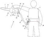
figure 1 shows a schematic view of a power saw assembly at an operator,
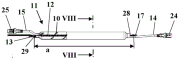
figure 2 shows a side view in partial cross-section of a rope assembly originating from the assembly of figure 1 in an unloaded state,
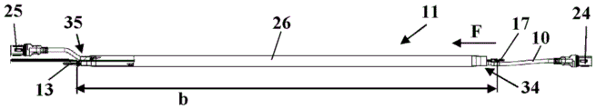
figure 3 shows a partly cut-away side view of the rope assembly originating from figure 2 in a fully stretched state,
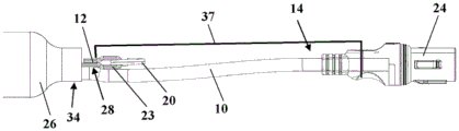
figure 4 shows an enlarged, partially cut-away view of the end region of the cable assembly to be fixed at the motor saw,
figure 5 shows an enlarged view of the end region of the rope assembly to be fixed at the operator,
figure 6 shows a schematic view of the attachment means of the rope assembly to the operator,
figure 7 shows an enlarged, partially cut-away view of the end region of the cable assembly to be fixed at the motor saw in the fully extended state,
figure 8 shows a cross-section along the line VIII-VIII in figure 2,
figure 9 shows a schematic cross-sectional view of the electrical connection of the electrical cables to the accumulator,
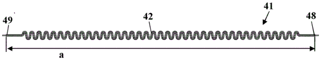
figure 10 shows a side view of a segment of one embodiment of a rope assembly in an unloaded state,
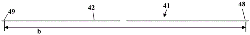
figure 11 shows the assembly from figure 10 in a fully stretched state,
figure 12 shows a partial perspective view of the rope assembly from figure 10,
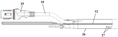
figure 13 shows a side view in partial cross-section of a section of one embodiment of a cord assembly in an unloaded state,
figure 14 shows a side view in partial cross-section of the assembly from figure 13 in a fully stretched state,
figure 15 shows an enlarged, partially cut-away view of the end region of the rope assembly originating from figure 13 in an unloaded state,
figure 16 shows an enlarged, partially cut-away view of the end region of the rope assembly originating from figure 13 in a fully stretched state,
figure 17 shows a side view in the direction of arrow XVII in figure 13,
figure 18 shows a perspective view of the end region of the rope assembly,
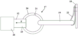
figure 19 shows a side view in partial cross-section of a section of one embodiment of a cord assembly in an unloaded state,
figure 20 shows a side view in partial cross-section of the assembly from figure 19 in a fully stretched state,
figure 21 shows an enlarged, partially cut-away side view of the end region of the rope assembly originating from figure 19 in an unloaded state,
figure 22 shows an enlarged, partially cut-away side view of the end region of the rope assembly originating from figure 19 in a fully stretched state,
figure 23 shows a side view in the direction of arrow XXIII in figure 19,
figure 24 shows a perspective view of the end region of the rope assembly from figure 19,
figure 25 shows an embodiment of a section of a rope assembly in side view,
figure 26 shows in an enlarged view the end of the rope assembly originating from figure 25,
figure 27 shows a side view in partial cross-section of a section of one embodiment of a cord assembly in an unloaded state,
figure 28 shows a side view in partial cross-section of the assembly from figure 27 in a fully stretched state,
figure 29 shows a cross-section along line XXIX-XXIX in figure 27,
figure 30 shows a perspective view of the end region of the rope assembly from figure 27,
figure 31 shows a schematic view of an embodiment of a power saw assembly at an operator,
figure 32 shows a perspective view of the attachment means of the power saw assembly from figure 31,
fig. 33 shows a side view of an embodiment of an end region of the cable assembly to be secured at the operator.
Detailed Description
Fig. 1 shows, as an example, a motorized saw assembly 1, the motorized saw assembly 1 comprises a motorized saw 3, a cable assembly 11 and a battery 9, the motorized saw 3 has a housing 4 at which a Handle 5 is fixed, the Handle 5 is configured as an upper Handle, the motorized saw 3 is a tree care saw (also referred to as a Top Handle saw (Top Handle-Säge)), in the illustration in fig. 1 the motorized saw 3 is held by an operator 2 at the upper Handle 5, a guide rail 7 is fixed at the housing 4, at which guide rail a saw chain 8 is guided, the saw chain 8 is driven in operation by a drive motor 6 arranged in the housing 4 in a manner surrounding the guide rail 7, the drive motor 6 is configured as an electric motor and is supplied with energy via an electric cable 10 connected to the battery 9, the electric cable 10 has a first end 14, at which the electric cable is connected to the battery 9 via an electric connector 16, the electric connector 16 can be arranged directly at the housing of the battery 9, it can however also be provided that the battery 9 is connected to the electric cable connector 16 via a plug connector, and the plug connector 15 is configured as a plug connector for example, which plug connector 15 can be arranged in the housing 4, and which plug connector is arranged in a plug connector 15 can be arranged in the housing 4, which plug connector can be pushed into the housing 4.
In particular, when working in trees, it is advantageous if the power saw is fastened to the operator 2 by means of a securing element 12. The securing element 12 is advantageously a securing cord. The securing element 12 is advantageously designed to be elastic, so that the securing element 12 can be stretched in its longitudinal direction. If the operator 2 moves in the tree, the operator can carry the motor saw 3 in a downwardly hanging manner (transportieren) at the safety element 12. Both hands of the operator 2 are thus free and do not restrict the freedom of movement of the operator by the motor saw 3. The securing element 12 is fixed to the housing 4 of the motor saw 3 by at least one fixing means 13. The securing means 13 can for example comprise a ring or the like which hooks into a clasp of the motor saw 3. The securing element 12 is held at the operator 2 by a connecting device 17. In this embodiment the operator 2 wears a carrier band 18 to which a safety hook (sometimes called snap hook/snap button) 19 is fixed. The connecting means 17, in this embodiment a ring, is hooked into the snap hook 19. If the motor-driven saw 3 is held, for example, on the carrier band 18, the securing element 12 is relatively short. In operation, when the operator 2 holds the power saw 3, the securing element 12 can be lengthened and thus a high freedom of movement is achieved when working with the power saw 3. If the motor-driven saw 3 is carried in a downwardly suspended manner at the securing element 12, the securing element 12 can be lengthened still further, in particular until a maximum length is reached.
The cable 10 and the fuse element 12 form a cable assembly 11. Thereby simplifying operation. The cable 10 and the fuse element 12 are connected to one another at least partially over a large part of their length in this embodiment. Thereby, blocking of the operator by the rope assembly 11 is largely avoided.
Fig. 2 shows the rope assembly 11 in an unloaded state. The fuse element 12 has: a first end section 28 at which the connecting means 17 are arranged; and a second end section 29, to which the fixing means 13 (in this embodiment a ring) is fixed. The securing element 12 has an unloaded length a from the first end section 28 to the second end section 29, i.e. from the connecting device 17 to the fastening means 13. The length a can be, for example, from about 50cm to about 1 m.
Fig. 3 shows the rope assembly 11 in a fully stretched state. In this state the cable assembly 11 has a length b between the fixing means 13 and the connecting device 17. The length b is significantly greater than the length a. The length b can be, for example, from about 75cm to about 1.6m, in particular from about 90cm to about 1.4 m. The length b is advantageously at least 150%, in particular at least 160%, of the unloaded length a. As shown in fig. 2 and 3, a first plug 24 of the plug connection is provided at the first end 14 of the electrical cable 10 and a second plug 25 is provided at the second end 15 of the electrical cable 10. The plugs 24 and 25 form parts of a plug connector for connecting the cable 10 with the battery 9 and the drive motor 6, respectively.
As fig. 2 and 3 also show, the cable 10 and the fuse element 12 are surrounded by the elastic sheath 26 approximately over the entire length from the first end section 28 to the second end section 29 of the fuse element 12. The sheath 26 is connected to the cable 10 and the fuse element 12 at a first fixing area 34 and a second fixing area 35. The sheath 26 connects the fuse element 12 and the cable line 10 to one another in a first fastening region 34 and also in a second fastening region 35.
As shown in the enlarged illustration in fig. 4, the cable 10 in this exemplary embodiment has two cable cores 27 which are guided within the sheath 26 without an additional cable jacket. The cable core 27 of the cable 10 is here wound loosely around the fuse element 12 and can rest against the inner periphery of the sheath 26. The cable core 27 is advantageously used for transferring electrical energy. Two further cable cores, not shown, are advantageously provided, which serve as signal lines and are likewise wound loosely around the fuse element 12. As fig. 4 also shows, the securing element 12 has a collar 31 adjacent to the fastening means 13, which collar can likewise be used for fastening.
Fig. 5 shows the first fixing area 34 and the first end 14 of the cable 10 in an enlarged view. The securing element 12 has a collar 23 at its first end section 28, in which the overload ring 20 is suspended. The securing element 12 is connected to the first plug part 24 via a connecting element 37, which is schematically illustrated in fig. 5. The connecting element 37, although bendable, is not yet stretched in the longitudinal direction of the cable 10 under the forces that normally act on the security element 12 during operation. The lengthening of the connecting element 37 advantageously takes place only with a force which lies above the pull-out force of the electrical connecting element 16. The connecting piece 37 can be formed, for example, by a cable jacket which is arranged around the cable core 27 and advantageously around the signal conductors which are provided in addition.
Fig. 6 schematically shows an overload ring 20. The ends of the overload ring 20 are not connected to each other so that the overload ring 20 has an opening 21. In the illustration in fig. 6, the overload ring 20 extends over a circumference of less than one complete circumference. It can however also be provided that the overload ring 20 extends around the ring center over an angle of significantly more than 360 ° and that the ends of the overload ring 20 are arranged to overlap. By the loose connection of the ends of the overload ring 20 to one another, the overload ring 20 can be pulled apart under the influence of forces (aufdehnnng). The overload ring 20 is hooked into a snap hook 19, which is itself held securely at the carrier band 18 by a collar 22. The loop 22 can, for example, be sewn securely to the carrier band 18 or can be securely connected to the carrier band 18 in another suitable manner.
The overload ring 20 is designed for the maximum acting tensile force. The maximum applied tensile force can be, for example, about 300N to about 500N. If the tensile force F acting on the securing element 12 exceeds the maximum tensile force of the overload ring 20, the overload ring 20 is stretched and the mechanical connection of the securing element 12 to the safety hook 19, i.e. to the operator 2, is released. This can be the case, for example, when the operator 2 carries the motorized saw 3 in a suspended manner at the rope assembly 11 and the motorized saw 3 hooks or clips into a tree or branch. The mechanical connection of the securing element 12 to the securing hook 19 is released. The cable assembly 11 is still connected to the operator 2 after the connection via the safety cable 12 has been released by the cable line 10 and the electrical connections at the ends 14 and 15 of the cable line 10. In order to ensure that the connection made via the cable 10 is released, the pull-out force of the electrical connection 16 is matched to the maximum pull-out force of the overload ring 20. The pull-out force for releasing the electrical connection is less than the maximum pull-out force. As soon as the mechanical connection of the securing element 12 to the securing hook 19 is released by exceeding the maximum tensile force, the maximum tensile force acts on the electrical connecting element 16.
The connection 37 (fig. 5) between the securing element 12 and the first plug 24 ensures that the entire tensile force F acting on the securing element 12 acts directly on the plug 24 and not on the cable 10. However, the connecting piece 37 can also be omitted. In this case, the electrical connection 16 can also be released between the electrical cable 10 and the plug 24. For this purpose, the pull-out force required for pulling the cable 10 off the plug 24 can be designed to be less than the maximum pull force. Once the electrical connection 16 has also been released, the power saw 3 is completely released from the operator 2 and the operator 2 can move independently of the power saw 3.
The pull-out force of the electrical connecting element 16 is advantageously at most half the maximum tensile force of the overload ring 20, in particular at most one fifth of the maximum tensile force of the overload ring 20. As soon as the mechanical connection between the securing element 12 and the securing hook 19 is released, a force which is significantly greater than the pull-out force of the electrical connection acts on the electrical connection 16, so that the electrical connection 16 is released reliably. The pull-out force of the electrical connection can be, for example, 10N to 250N, advantageously 20N to 100N, in particular about 40N to about 60N.
As shown in the enlarged illustration in fig. 7, the cable core 27 of the cable 10 is wound loosely around the fuse element 12 even in the fully extended state of the fuse element 12, i.e. at the maximum length b of the fuse element 12. The length of the cable 10 is greater than the length of the fuse element 12.
The cross-sectional view in fig. 8 shows the structure of the rope assembly 11 in detail. The sheath 26 surrounds both the cable 10 (with its two cores 27) and the fuse element 12. The securing element 12 is formed in this exemplary embodiment from two components, namely an internal elastic band 32, for example a rubber band, and a length limitation 33 surrounding the elastic band 32. The length limitation 33 can be, for example, a textile or plastic hose and, as shown in fig. 4, be folded in the unloaded state of the cable assembly 11. As fig. 7 shows, the length limitation 33 is configured to be flat in the fully extended state of the securing element 12. The number and size of the folds determines the amount of stretching possible. In the completely pulled-out state, the length limitation 33 cannot be further extended under the normal forces during operation and thus limits the maximum extended length b of the securing element.
As fig. 8 also shows, the fuse element 12 has a relatively small distance c from the cable 10. The spacing c is advantageously less than 15cm, preferably less than 10cm, at each location of the rope assembly 11. A spacing of less than 5cm has proven to be particularly preferred. The outer diameter of the rope assembly 11 can thus be chosen relatively small and preferably less than 10 cm. In this exemplary embodiment, the cable 10 and the fuse element 12 are connected to one another approximately over their entire length. The fuse element 12 extends completely within the sheath 26 from the fixing means 13 up to the connecting device 17. The ends 14 and 15 of the cable 10 protrude from the sheath 26 with a small section of the cable 10 in order to make it possible to easily couple the plugs 24 and 25 to the associated mating plugs of the battery 9 and the motor saw 3, respectively.
Fig. 9 schematically shows an electrical connection 16. The battery 9 has a mating plug 36 for the plug 24, which mating plug 36 is configured as a socket in this exemplary embodiment and into which mating plug 36 the first plug 24 can be inserted. It is advantageously possible to integrate the overload safeguard at the first plug part 24.
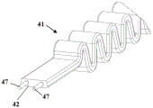
Fig. 10 to 12 show an embodiment of a cable assembly 41 in which the cable cores 47 of the cable lines 10 are integrated at the fuse element 42. The securing element 42 is formed from a flexurally flexible or elastically shaped plastic material, which, as shown in fig. 12, is embodied in this exemplary embodiment as solid and in which the cable core 47 of the cable 10 is embedded. The cable core 47 is embedded in the material of the fuse element 42 in this exemplary embodiment without a common cable jacket. The securing element 42 can be made, for example, of a thermally deformable plastic material which is corrugated in the unstretched state, as is shown in fig. 10. In this state, the securing element 42 has a length a, which is measured from the first end section 48 to the second end section 49 of the securing element 42. At the end sections 48 and 49, the fastening means 13, which is not shown in fig. 10 to 12, and the connecting device 17, which is not shown in fig. 10 to 12, are arranged (fig. 3).
Fig. 11 shows the securing element 42 in the fully extended state. In this state, the securing element 42 has a length b, measured from the first end section 48 to the second end section 49, which advantageously amounts to at least 150%, in particular at least 160%, of the length a. In this exemplary embodiment, the securing element 42 no longer has a wave in the fully extended state, but is rather flat. The securing element 42 assumes a length limitation in the fully extended state, since the securing element 42 cannot be extended further. The securing element 42 can also be a fabric strip or the like.
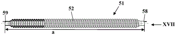
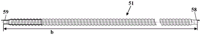
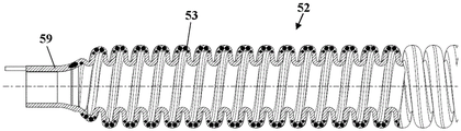
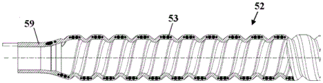
Fig. 13 to 18 show an embodiment of a cable assembly 51 with a securing element 52. Also not shown here are the fixing means 13 and the connecting device 17. The securing element 52 has a first end section 58 and a second end section 59, wherein the not shown fastening means 13 and the not shown connecting device 17 are arranged at the first end section 58 and the second end section 59, respectively. The security element has a length a in the unstretched state. The securing element 52 is of tubular design, depending on the type of the hose coil, and has a helically circumferential bulge 53, which is visible both in the unstretched state (fig. 15) and in the fully stretched state (fig. 16) of the securing element 52. The securing element 52 can be designed in such a way that it cannot be further stretched in relation to the stretched state shown in fig. 15 and 16 and therefore exhibits a length limitation. However, additional length restrictions can also be provided (for example in the form of a cable guided by the securing element 52).
As fig. 17 and 18 show, the cable 10, which in this exemplary embodiment comprises two cable cores 57 and two signal lines 56, is guided in the wall of the securing element 52. The cable core 57 and the signal lines 56 are each guided in the material of the fuse element 52 without a common cable jacket. The securing element 52 can be made of plastic, for example.
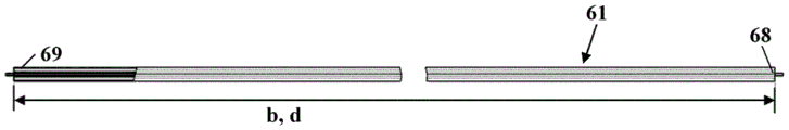
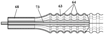
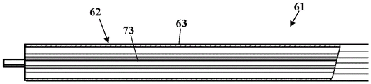
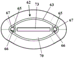
Fig. 19 to 24 show another embodiment of the rope assembly 61. The rope assembly 61 has a first end section 68 and a second end section 69, at which first end section 68 and second end section 69 the fixing means 13 and the connecting device 17 can be fixed. The cable assembly 61 has a length a in an unstretched state. The cable combination 61 has a securing element 62, which comprises a hose-shaped sheath 63 in which an elastic element 73 is guided. The sheath 63 has a plurality of folds 64 and is thereby stretchable in the longitudinal direction of the sheath. The elastic element 73 is configured as shown in fig. 23 and 24 to be flat and can be, for example, a rubber band or the like. The elastic element 73 is elastic due to its material and urges the rope assembly 61 to shorten when the force acting at the rope assembly 61 is reduced. As fig. 20 and 22 show, the sheath 63 of the securing element 62 is designed to be flat in the fully extended state. However, it can also be provided that the sheath 63 has a fold even in the fully stretched state. The securing element 62 has a length b from its first end section 68 up to its second end section 69 in the fully extended state.
As fig. 23 and 24 show, the cable core 67 and the signal lines 66 of the electrical cable 10 are guided in the sheath 63 without a common cable jacket for the purpose of encapsulation. In this exemplary embodiment, the sheath 63 is flat and has an approximately oval cross section or a flattened circular cross section, wherein recesses 65 are provided at the narrow sides, in which recesses the respective signal lines 66 and cable cores 67 of the cable 10 are guided. The elastic element 63 is guided in a space 70 located between these recesses, which is separated from the recess 65. However, the recess 65 can also be dispensed with and the cable core 67 and the signal lines 66 can be guided together with the spring element 63 in the space 70. The sheath 63 of the fuse element 62 forms a length limiter for the rope assembly 61. The sheath 63 can be, for example, a textile hose tape. The cable 10 with the cable core 67 and the signal line 66 has a length d shown in fig. 20, which corresponds to the length b of the securing element 62 and the cable combination 61 from the first end section 68 to the second end section 69. The cable 10 is thus not stretched in its length with maximum tensioning of the securing element 62. The length d can also be greater than the length b.
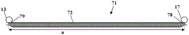
Fig. 25 and 26 show an embodiment of a cable assembly 71 comprising a fuse element 72. The securing element 72 is designed as a fabric hose, the connecting device 17 being fastened to a first end section 78 of the securing element and the fastening means 13 being fastened to a second end section 79 of the securing element. The cable 10 extends through the fuse element 72. The length restriction is formed by a copper part of the cable 10. However, it can also be provided that the securing element 72 forms a length limitation due to its woven structure. The fuse element 72 can abut against the outer circumference around the cable 10 in the fully stretched state. However, it can also be provided that a spacing exists between the cable 10 and the fuse element 72. The securing element 72 is designed to be elastic and to be retracted substantially into its original length when the force no longer has an effect on the securing element 72.
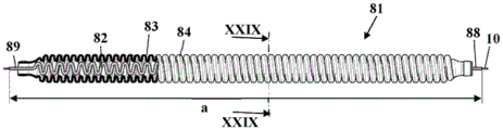
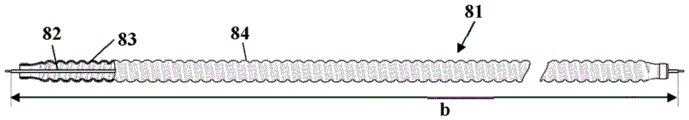
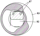
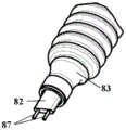
Fig. 27 to 30 show an embodiment of a rope assembly 81 comprising a sheath 83 through which a fuse element 82 extends. The jacket 83 is configured in the form of a tube and has a helical bulge 84, which allows the jacket 83 to be stretched in length. The sheath 83 can be made of plastic, for example. The elasticity can be due to the bulge 84 or be derived from the elasticity of the material. In the unloaded state shown in fig. 27, the securing element 82 is of undulating design and can be made, for example, of a thermally deformable plastic. The securing element 82 advantageously corresponds to the securing element 42 (fig. 10). Two cores 87 of the cable 10 are embedded in the securing element 82, which are completely surrounded by the material of the securing element 82. In the extended state of the cable assembly 81 shown in fig. 28, the securing element 82 is configured to be flat. The fuse element 82 can form a length limitation of the rope assembly 81. However, it can also be provided that the length limitation is formed by a sheath 83. The connecting device 17 may be fixed at the first end section 88 of the rope assembly 81 and the fixing means 13 may be fixed at the second end section 89.
Fig. 31 and 32 show an embodiment of a motorised saw assembly 1. The power saw assembly 1 includes a cable assembly 91 that connects the power saw 3 with the operator 2. The structure of the cable assembly 91 can here correspond to the structure of any of the cable assemblies 11,41,51,61,71,81 shown in the preceding embodiments. The attachment device 97 is releasably secured at the cable assembly 91. The connecting device 97 can be at least partially released from the cable assembly 91 and fixed in different positions on the cable assembly 91. The connecting means 97 is in this embodiment arranged to be attached to the connecting means 17. However, it can also be provided that only one connection device 97 is provided which can be fastened in different positions at the cable assembly 91 and is not fastened to the cable assembly 17.
Fig. 32 shows the design of the connecting device 97 in detail. The attachment device 97 includes a clamping device 99 releasably secured at the cable assembly 91. The clamping device 99 comprises in this embodiment a first clamping shell 101 and a second clamping shell 102, which are connected to each other by means of a fixing means 103. The fixing means 103 can be, for example, a threaded fastener or a quick-clamping device. In order to displace the clamping device 99 relative to the cable assembly 91, the at least one fixing means 103 is released, so that the clamping shells 101 and 102 can be displaced relative to the cable assembly 91. Once the holding device 99 is in the desired position, the at least one fixing means 103 is fixed again. As shown in fig. 32, in this exemplary embodiment, an overload ring 100, into which the fastening snap ring 98 hooks, is held at the first clamping shell 101. The connecting device 97 can be fastened, for example, to the snap hook 19 of the carrier band 18 by means of a fastening buckle 98.
It can also be provided that the connecting device 97 does not have an overload ring 100. In this case, the connecting device 97 is provided only for carrying the motor-driven saw 3 and is not provided for use when the motor-driven saw 3 is in operation.
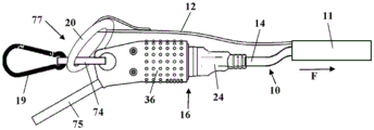
Fig. 33 shows an embodiment of a connection device 77 for connecting the cable assembly 11 to a user. The same reference symbols are used herein to designate corresponding elements in all the figures. The connecting device 77 comprises an overload ring 20 connected to the fuse element 12. The overload ring 20 is held in a ring element 74, at which the mating plug element 36 is also held with limited movement. The loop 74 hooks into the snap hook 19 of the user 2. The electrical connector 16 is designed as a plug connector and is formed by a first plug part 24, which is inserted into a mating plug part 36. By the fact that the mating plug 36 is fixed in a movement-limited manner at the ring 74, the mating plug 36 can be oriented in the direction of the tensile force F acting at the cable 10 and the cable assembly 11. A simple, compact construction is achieved by arranging the overload ring 20 at the electrical connection 16. The overload ring 20 is also designed such that, if a maximum tensile force F is exceeded, the overload ring 20 is opened and releases the mechanical connection between the safety hook 19 and the securing element 12. The pull-out force of the electrical connecting element 16 is less than the maximum effective pull force, so that the electrical connecting element 16 is also released directly after the release of the connecting device 77. The mating plug 36 is connected to the battery 9 by a coupling cable 75. This allows a limited movement of the plug 36 to be arranged in a simple manner.
Claims (19)
1. Motor-driven saw assembly with a motor-driven saw (3) having a housing (4) at which a guide rail (7) is fixed, with an electric drive motor (6) which drives a saw chain (8) arranged around the guide rail (7), wherein the drive motor (6) is supplied with energy from at least one battery (9), wherein the battery (9) is arranged outside the housing (4) of the motor-driven saw (3) and is connected to the drive motor (6) by an electric cable (10), wherein the electric cable (10) has a first end (14) which is connected to the battery (9) at an electric connection (16) and a second end (15) which is held at the motor-driven saw (3), characterized in that the motor-driven saw (3) has an elastic securing element (12), 42,52,62,72,82), wherein the securing element (12,42,52,62,72,82) is fixed to the housing (4) of the motor saw (3) by means of at least one fixing means (13), and wherein at least one connecting device (17,77,97) is provided for connecting the securing element (12,42,52,62,72,82) to a user (2), wherein the connecting device (17,77,97) has an overload fuse which releases the mechanical connection of the securing element (12,42,52,62,72,82) to the user (2) if a maximum tensile force acting at the securing element (12,42,52,62,72,82) is exceeded, wherein the securing element (12,42,52,62,72,82) forms a cable assembly (11) with the cable line (10), 41,51,61,71,81,91), and wherein the pull-out force for releasing the electrical connection (16) is smaller than the maximum pull force, so that a mechanical connection between the securing element (12,42,52,62,72,82) and the user is released if a force greater than the maximum pull force of the overload securing element acts on the securing element (12,42,52,62,72,82), wherein after releasing the mechanical connection a pull force acts on the electrical connection (16) between the cable (10) and the battery (9), and since the pull-out force for releasing the electrical connection (16) is smaller than the maximum pull force, the electrical connection (16) is also released, so that the user can move independently of the motor saw (3).
2. The power saw assembly according to claim 1, wherein the pull-out force of the electrical connector (16) is at most half the maximum pull-out force.
3. The power saw assembly according to claim 1, wherein the cable assembly (11,41,51,61,71,81,91) has means for connecting the electrical cable (10) with the fuse element (12,42,52,62,72, 82).
4. The power saw assembly according to claim 3, wherein the electrical cable (10) is fixed at the fuse element (12,42,52,62) adjacent to the fixing means (13).
5. The power saw assembly according to claim 3, wherein the electrical cable (10) is fixed at the fuse element (12,42,52,62) adjacent to the connecting means (17, 77).
6. The power saw assembly according to claim 1, wherein the connecting device (97) is fixable at the rope assembly (91) in at least two positions.
7. The power saw assembly according to claim 1, wherein the electrical cable (10) is connected at least loosely to the securing element (12,42,52,62,72,82) over at least 50% of the length (a) of the securing element (12,42,52,62,72,82) between the fixing means (13) and the connecting device (17,77,97), such that the spacing (c) between the securing element (12,42,52,62,72,82) and the electrical cable (10) is less than 15cm in each region.
8. The power saw assembly according to claim 7, characterized in that the electric cable (10) is coiled around the fuse element (12) in a region in which the electric cable (10) is connected with the fuse element (12).
9. The power saw assembly according to claim 7, characterized in that the electric cable (10) is guided within the safety element (42,52,72,82) in a region in which the electric cable is connected with the safety element (42,52,72, 82).
10. The power saw assembly according to claim 1, wherein the cable assembly (11,61,81,91) comprises a sheath (26,63,84) in which the fuse element (12,62,82) and the electric cable (10) are guided over at least a partial region of their length.
11. The motorised saw assembly according to claim 10, characterized in that said sheath (26,63,82) extends from said fixing means (13) up to said connection means (17,77, 97).
12. The power saw assembly according to claim 1, wherein the cable assembly (11,41,51,61,71,81,91) has a length limitation (33) for limiting the maximum stretched length (b) of the safety element (12,42,52,62,72, 82).
13. The motorised saw assembly according to claim 12, wherein the maximum stretched length (b) of the securing element (12,42,52,62,72,82) between the securing means (13) and the connecting means (17,77,97) is at least 150% of the unloaded length (a) of the securing element (12,42,52,62,72,82) between the securing means (13) and the connecting means (17,77, 97).
14. The power saw assembly according to claim 12, wherein the length (d) of the electrical cable (10) corresponds at least to the maximum stretched length (b) of the fuse element (12,42,52,62,72, 82).
15. The motorised saw assembly according to claim 1, characterized in that said first end (14) of said electric cable (10) carries a plug (24) of a plug connector, which is electrically connected with a counterpart plug (36) of said accumulator (9).
16. The motorized saw assembly according to claim 15, wherein the counter plug (36) is held with limited movement and can be oriented in the direction of a pulling force (F) acting at the electric cable (10).
17. The power saw assembly according to claim 15, wherein the cable assembly (11,41,51,61,71,81,91) has a length limitation (33) for limiting the maximum stretched length (b) of the safety element (12,42,52,62,72,82), wherein the plug (24) of the electrical cable (10) is securely connected with the length limitation (33) of the safety element (12).
18. The motorized saw assembly of claim 15, wherein the overload safeguard is disposed at the plug connector.
19. A rope assembly for a motor saw, wherein the rope assembly (11,41,51,61,71,81,91) comprises a resilient fuse element (12,42,52,62,72,82) and an electric cable (10), wherein the rope assembly (11,41,51,61,71,81,91) has at least one fixing means (13) with which the fuse element (12,42,52,62,72,82) can be fixed at a housing (4) of a motor saw (3), and wherein the rope assembly (11,41,51,61,71,81,91) has at least one connecting device (17,77,97) for connection with a user (2), wherein the connecting device (17,77,97) has an overload fuse which acts on the fuse element (12,42,52,62,72,82) is exceeded, wherein the electrical cable (10) carries the plug (24) of the electrical connection (16), wherein the pull-out force of the electrical connection (16) is less than the maximum pull-out force, the mechanical connection of the securing element (12,42,52,62,72,82) to the user (2) is released.
Applications Claiming Priority (2)
| Application Number | Priority Date | Filing Date | Title |
|---|---|---|---|
| EP14003913.2A EP3023201B1 (en) | 2014-11-20 | 2014-11-20 | Motorised saw assembly and cable module for a motorised saw |
| EP14003913.2 | 2014-11-20 |
Publications (2)
| Publication Number | Publication Date |
|---|---|
| CN105619552A CN105619552A (en) | 2016-06-01 |
| CN105619552B true CN105619552B (en) | 2020-03-06 |
Family
ID=51999199
Family Applications (1)
| Application Number | Title | Priority Date | Filing Date |
|---|---|---|---|
| CN201510804790.3A Active CN105619552B (en) | 2014-11-20 | 2015-11-20 | Motorized saw assembly and cord assembly for a motorized saw |
Country Status (3)
| Country | Link |
|---|---|
| US (1) | US10717206B2 (en) |
| EP (1) | EP3023201B1 (en) |
| CN (1) | CN105619552B (en) |
Families Citing this family (17)
| Publication number | Priority date | Publication date | Assignee | Title |
|---|---|---|---|---|
| US20170014984A1 (en) * | 2015-07-16 | 2017-01-19 | Apex Brands, Inc. | High-power lightweight tool |
| US10716390B2 (en) | 2017-12-21 | 2020-07-21 | Milwaukee Electric Tool Corporation | Lanyard |
| CN108080723A (en) * | 2017-12-22 | 2018-05-29 | 宁波星瑞克中空铝条有限公司 | The saw cutting device of aluminum strip in a kind of hollow glass |
| US11964356B2 (en) * | 2018-04-05 | 2024-04-23 | Makita Corporation | Hand-held tool |
| CN211671502U (en) * | 2018-12-11 | 2020-10-16 | 南京德朔实业有限公司 | Garden Tools |
| WO2021064086A1 (en) * | 2019-10-02 | 2021-04-08 | Husqvarna Ab | Battery adapter assembly and hand-held power tool |
| EP4056307B1 (en) * | 2019-12-31 | 2024-04-03 | Nanjing Chervon Industry Co., Ltd. | Chainsaw |
| US12064894B2 (en) | 2020-09-04 | 2024-08-20 | Milwaukee Electric Tool Corporation | Chainsaw |
| EP4000812A3 (en) * | 2020-10-29 | 2022-08-03 | Black & Decker Inc. | Lanyard |
| DE102020216582A1 (en) * | 2020-12-29 | 2022-06-30 | Robert Bosch Gesellschaft mit beschränkter Haftung | hand tool |
| JP7773095B2 (en) * | 2022-02-28 | 2025-11-19 | 工機ホールディングス株式会社 | Work equipment |
| EP4382177A1 (en) * | 2022-12-07 | 2024-06-12 | 3M Innovative Properties Company | Fall protection device |
| IT202200025536A1 (en) * | 2022-12-14 | 2024-06-14 | Tecna Spa | TOOL BALANCER. |
| IT202300010887A1 (en) * | 2023-05-30 | 2024-11-30 | Tecna Spa | BALANCER FOR TOOLS, EQUIPMENT AND LOADS IN GENERAL. |
| DE102023134320B4 (en) * | 2023-12-07 | 2025-06-18 | Andreas Stihl Ag & Co. Kg | User-portable battery pack holder and user-portable processing system |
| SE547522C2 (en) * | 2024-02-29 | 2025-10-07 | Husqvarna Ab | Cable, Power Supply System for a Handheld Power Tool, and Power Tool System |
| DE102024117131A1 (en) | 2024-06-18 | 2025-12-18 | Andreas Stihl Ag & Co. Kg | User-portable machining system |
Citations (4)
| Publication number | Priority date | Publication date | Assignee | Title |
|---|---|---|---|---|
| US4558495A (en) * | 1982-06-18 | 1985-12-17 | Olsen Torbjoern | Holder, especially for a drill chuck key |
| US5711055A (en) * | 1996-10-03 | 1998-01-27 | Quick; Todd N. | Electrical cord strain relief apparatus |
| CN101391424A (en) * | 2007-09-21 | 2009-03-25 | 安德烈亚斯.斯蒂尔两合公司 | Motor chain saw |
| CN101521364A (en) * | 2008-02-27 | 2009-09-02 | 安德烈亚斯.斯蒂尔两合公司 | Implement with train relief mechanism for connection cable |
Family Cites Families (20)
| Publication number | Priority date | Publication date | Assignee | Title |
|---|---|---|---|---|
| US2913791A (en) * | 1955-08-09 | 1959-11-24 | Martin Harry | Captive plug coupling |
| US4698717A (en) * | 1985-07-02 | 1987-10-06 | Scheid William J | Electrical safety drop disconnect |
| US4667460A (en) * | 1986-01-17 | 1987-05-26 | Joseph Kramer | Electric lawn mower with self coiling power cord |
| US5394592A (en) * | 1994-02-02 | 1995-03-07 | Quick; Todd N. | Power tool cord strain relief arrangement |
| DE29808030U1 (en) * | 1998-05-05 | 1999-09-16 | Schrey, Gerhard, 38179 Schwülper | Barrier rope with internal power or EDP cable for exhibitions, trade fairs and museums or to cordon off danger zones |
| US6299040B1 (en) * | 1999-07-02 | 2001-10-09 | Buckingham Manufacturing Co., Inc. | Tear-away retaining lanyard |
| US6776317B1 (en) * | 2001-03-19 | 2004-08-17 | Parker Systems, Inc. | Tool lanyard for holding tools |
| US6461192B1 (en) * | 2001-04-30 | 2002-10-08 | Microsoft Corporation | Breakaway cable connector |
| US7661737B2 (en) * | 2005-05-23 | 2010-02-16 | Slingmax, Inc. | Sling with predictable pre-failure warning indicator |
| US8291939B2 (en) * | 2005-07-29 | 2012-10-23 | Sykes Hollow Innovations, Ltd. | Grounding system for a heated hose |
| US7458135B2 (en) * | 2005-11-21 | 2008-12-02 | Castle Mountain Enterprises, Llc | Tether |
| US7592544B2 (en) * | 2006-03-07 | 2009-09-22 | Ems Technologies, Inc. | Snag-free coiled cable assembly for a lift truck |
| US20080163464A1 (en) * | 2007-01-04 | 2008-07-10 | Raymond Baumann | Safety cable for holding tools |
| FR2920683B1 (en) | 2007-09-06 | 2010-02-12 | Pellenc Sa | MULTIPURPOSE ELECTROPORTATIVE DEVICES. |
| FR2925384B1 (en) * | 2007-12-20 | 2011-11-18 | Pellenc Sa | PORTABLE ELECTRIC CHAIN SAW |
| US8241053B2 (en) * | 2009-09-10 | 2012-08-14 | Vocollect, Inc. | Electrical cable with strength member |
| US8556223B2 (en) * | 2010-06-28 | 2013-10-15 | Electric Motion Company, Inc. | Break-away hook assembly |
| US8410369B2 (en) * | 2010-07-09 | 2013-04-02 | Chargepoint, Inc. | Breakaway mechanism for charging cables of electric vehicle charging stations |
| WO2013080233A1 (en) * | 2011-12-01 | 2013-06-06 | Redcap Technology S.R.L. | Safety device applicable to chainsaws |
| US20160374407A1 (en) * | 2015-06-23 | 2016-12-29 | David S. Yagerman | Safety vest with retractable tool tethers and integrated helmet |
-
2014
- 2014-11-20 EP EP14003913.2A patent/EP3023201B1/en active Active
-
2015
- 2015-11-18 US US14/944,247 patent/US10717206B2/en active Active
- 2015-11-20 CN CN201510804790.3A patent/CN105619552B/en active Active
Patent Citations (4)
| Publication number | Priority date | Publication date | Assignee | Title |
|---|---|---|---|---|
| US4558495A (en) * | 1982-06-18 | 1985-12-17 | Olsen Torbjoern | Holder, especially for a drill chuck key |
| US5711055A (en) * | 1996-10-03 | 1998-01-27 | Quick; Todd N. | Electrical cord strain relief apparatus |
| CN101391424A (en) * | 2007-09-21 | 2009-03-25 | 安德烈亚斯.斯蒂尔两合公司 | Motor chain saw |
| CN101521364A (en) * | 2008-02-27 | 2009-09-02 | 安德烈亚斯.斯蒂尔两合公司 | Implement with train relief mechanism for connection cable |
Also Published As
| Publication number | Publication date |
|---|---|
| US20160144530A1 (en) | 2016-05-26 |
| EP3023201A1 (en) | 2016-05-25 |
| CN105619552A (en) | 2016-06-01 |
| EP3023201B1 (en) | 2017-09-06 |
| US10717206B2 (en) | 2020-07-21 |
Similar Documents
| Publication | Publication Date | Title |
|---|---|---|
| CN105619552B (en) | Motorized saw assembly and cord assembly for a motorized saw | |
| US20120121120A1 (en) | Non-entangling electrical cables | |
| US20130074783A1 (en) | Leash slack control system | |
| US8269110B2 (en) | Scrunch-it earpiece / wire organizer and method of using same | |
| US9095125B2 (en) | Retractable leash with pliabile handle | |
| US20130192539A1 (en) | No-slack length-limited elastic leash | |
| WO2012135075A1 (en) | Cable management system and method of use | |
| EP2286173A2 (en) | System and method for quick release | |
| US20170360007A1 (en) | Pet Lease Device with a Buffering Function | |
| US8637772B2 (en) | Electric cord securing device and methods of use thereof | |
| US8209820B1 (en) | Cord-retaining fastener for bundled cords | |
| KR102051430B1 (en) | Lead Apparatus of Companion Animal | |
| US1708165A (en) | Coiling device | |
| KR20110003728U (en) | Charger (power supply) | |
| US7488199B2 (en) | Bundling apparatus for electrical cables | |
| JP6892791B2 (en) | Connector protector | |
| US7699643B1 (en) | Electrical cord management device | |
| WO2006024074A1 (en) | Tangle free lead | |
| US9889039B2 (en) | Penile constriction device | |
| CN216651384U (en) | Joint protective sheath is used to rheumatism immunity branch of academic or vocational study with protect function | |
| JP2012198992A (en) | Reduction structure of deformation or entanglement of curl occurring at curl forming part of curl cord | |
| US20180183178A1 (en) | Cable stress reliever | |
| KR101415758B1 (en) | A cable band for a cable fasciation | |
| JP2017060452A (en) | Lead for pet | |
| EP2760387B1 (en) | Penile constriction device |
Legal Events
| Date | Code | Title | Description |
|---|---|---|---|
| C06 | Publication | ||
| PB01 | Publication | ||
| SE01 | Entry into force of request for substantive examination | ||
| SE01 | Entry into force of request for substantive examination | ||
| GR01 | Patent grant | ||
| GR01 | Patent grant |