CN105515212B - Phantom motor system with parallel coils - Google Patents
Phantom motor system with parallel coils Download PDFInfo
- Publication number
- CN105515212B CN105515212B CN201510649286.0A CN201510649286A CN105515212B CN 105515212 B CN105515212 B CN 105515212B CN 201510649286 A CN201510649286 A CN 201510649286A CN 105515212 B CN105515212 B CN 105515212B
- Authority
- CN
- China
- Prior art keywords
- rotor
- receive
- magnetic field
- transmit
- coil
- Prior art date
- Legal status (The legal status is an assumption and is not a legal conclusion. Google has not performed a legal analysis and makes no representation as to the accuracy of the status listed.)
- Active
Links
Images


Classifications
-
- H—ELECTRICITY
- H02—GENERATION; CONVERSION OR DISTRIBUTION OF ELECTRIC POWER
- H02K—DYNAMO-ELECTRIC MACHINES
- H02K3/00—Details of windings
- H02K3/04—Windings characterised by the conductor shape, form or construction, e.g. with bar conductors
- H02K3/18—Windings for salient poles
- H02K3/20—Windings for salient poles for auxiliary purposes, e.g. damping or commutating
-
- H—ELECTRICITY
- H02—GENERATION; CONVERSION OR DISTRIBUTION OF ELECTRIC POWER
- H02P—CONTROL OR REGULATION OF ELECTRIC MOTORS, ELECTRIC GENERATORS OR DYNAMO-ELECTRIC CONVERTERS; CONTROLLING TRANSFORMERS, REACTORS OR CHOKE COILS
- H02P31/00—Arrangements for regulating or controlling electric motors not provided for in groups H02P1/00 - H02P5/00, H02P7/00 or H02P21/00 - H02P29/00
-
- H—ELECTRICITY
- H02—GENERATION; CONVERSION OR DISTRIBUTION OF ELECTRIC POWER
- H02K—DYNAMO-ELECTRIC MACHINES
- H02K11/00—Structural association of dynamo-electric machines with electric components or with devices for shielding, monitoring or protection
- H02K11/0094—Structural association with other electrical or electronic devices
-
- H—ELECTRICITY
- H02—GENERATION; CONVERSION OR DISTRIBUTION OF ELECTRIC POWER
- H02K—DYNAMO-ELECTRIC MACHINES
- H02K11/00—Structural association of dynamo-electric machines with electric components or with devices for shielding, monitoring or protection
- H02K11/30—Structural association with control circuits or drive circuits
- H02K11/35—Devices for recording or transmitting machine parameters, e.g. memory chips or radio transmitters for diagnosis
-
- H—ELECTRICITY
- H02—GENERATION; CONVERSION OR DISTRIBUTION OF ELECTRIC POWER
- H02K—DYNAMO-ELECTRIC MACHINES
- H02K3/00—Details of windings
- H02K3/04—Windings characterised by the conductor shape, form or construction, e.g. with bar conductors
- H02K3/28—Layout of windings or of connections between windings
-
- H—ELECTRICITY
- H02—GENERATION; CONVERSION OR DISTRIBUTION OF ELECTRIC POWER
- H02K—DYNAMO-ELECTRIC MACHINES
- H02K3/00—Details of windings
- H02K3/46—Fastening of windings on the stator or rotor structure
- H02K3/47—Air-gap windings, i.e. iron-free windings
-
- H—ELECTRICITY
- H02—GENERATION; CONVERSION OR DISTRIBUTION OF ELECTRIC POWER
- H02K—DYNAMO-ELECTRIC MACHINES
- H02K37/00—Motors with rotor rotating step by step and without interrupter or commutator driven by the rotor, e.g. stepping motors
- H02K37/02—Motors with rotor rotating step by step and without interrupter or commutator driven by the rotor, e.g. stepping motors of variable reluctance type
- H02K37/08—Motors with rotor rotating step by step and without interrupter or commutator driven by the rotor, e.g. stepping motors of variable reluctance type with rotors axially facing the stators
-
- H—ELECTRICITY
- H02—GENERATION; CONVERSION OR DISTRIBUTION OF ELECTRIC POWER
- H02P—CONTROL OR REGULATION OF ELECTRIC MOTORS, ELECTRIC GENERATORS OR DYNAMO-ELECTRIC CONVERTERS; CONTROLLING TRANSFORMERS, REACTORS OR CHOKE COILS
- H02P27/00—Arrangements or methods for the control of AC motors characterised by the kind of supply voltage
- H02P27/04—Arrangements or methods for the control of AC motors characterised by the kind of supply voltage using variable-frequency supply voltage, e.g. inverter or converter supply voltage
-
- H—ELECTRICITY
- H04—ELECTRIC COMMUNICATION TECHNIQUE
- H04B—TRANSMISSION
- H04B5/00—Near-field transmission systems, e.g. inductive or capacitive transmission systems
- H04B5/20—Near-field transmission systems, e.g. inductive or capacitive transmission systems characterised by the transmission technique; characterised by the transmission medium
- H04B5/24—Inductive coupling
- H04B5/26—Inductive coupling using coils
- H04B5/263—Multiple coils at either side
-
- H—ELECTRICITY
- H04—ELECTRIC COMMUNICATION TECHNIQUE
- H04B—TRANSMISSION
- H04B5/00—Near-field transmission systems, e.g. inductive or capacitive transmission systems
- H04B5/70—Near-field transmission systems, e.g. inductive or capacitive transmission systems specially adapted for specific purposes
-
- H—ELECTRICITY
- H02—GENERATION; CONVERSION OR DISTRIBUTION OF ELECTRIC POWER
- H02K—DYNAMO-ELECTRIC MACHINES
- H02K19/00—Synchronous motors or generators
- H02K19/02—Synchronous motors
- H02K19/10—Synchronous motors for multi-phase current
- H02K19/103—Motors having windings on the stator and a variable reluctance soft-iron rotor without windings
-
- H—ELECTRICITY
- H02—GENERATION; CONVERSION OR DISTRIBUTION OF ELECTRIC POWER
- H02P—CONTROL OR REGULATION OF ELECTRIC MOTORS, ELECTRIC GENERATORS OR DYNAMO-ELECTRIC CONVERTERS; CONTROLLING TRANSFORMERS, REACTORS OR CHOKE COILS
- H02P2201/00—Indexing scheme relating to controlling arrangements characterised by the converter used
- H02P2201/05—Capacitive half bridge, i.e. resonant inverter having two capacitors and two switches
Landscapes
- Engineering & Computer Science (AREA)
- Power Engineering (AREA)
- Computer Networks & Wireless Communication (AREA)
- Signal Processing (AREA)
- Connection Of Motors, Electrical Generators, Mechanical Devices, And The Like (AREA)
- Synchronous Machinery (AREA)
- Control Of Ac Motors In General (AREA)
Abstract
本公开涉及具有平行线圈的幻影电动机系统。提出了用于操作电动机的方法和设备。在具有基本上平行于来自发射线圈的磁场线而定位的一组轴线并且具有一组谐振频率的一组接收线圈处接收发射磁场。该一组谐振频率中的谐振频率不同于该一组接收线圈中的其他接收线圈。当发射磁场具有匹配谐振频率的选定频率时,在该一组接收线圈中具有谐振频率的接收线圈处生成接收磁场。接收磁场吸引电动机中的转子。

The present disclosure relates to phantom motor systems with parallel coils. A method and apparatus for operating an electric motor are presented. The transmit magnetic field is received at a set of receive coils having a set of axes positioned substantially parallel to the magnetic field lines from the transmit coil and having a set of resonant frequencies. Resonant frequencies in the set of resonant frequencies are different from other receive coils in the set of receive coils. When the transmit magnetic field has a selected frequency that matches the resonant frequency, a receive magnetic field is generated at the receive coil having the resonant frequency in the set of receive coils. The receiving magnetic field attracts the rotor in the motor.
Description
技术领域technical field
本公开内容总体上涉及一种电动机系统,并且具体地,涉及一种无刷电动机。更具体地,本公开内容涉及用于具有平行线圈的幻影发动机(phantom motor)的方法和设备。The present disclosure relates generally to an electric motor system, and in particular, to a brushless electric motor. More specifically, the present disclosure relates to methods and apparatus for phantom motors with parallel coils.
背景技术Background technique
电动机是将一种将电能转换为机械能的装置。电动机可以被用于各种应用。电动机(例如但不限于)可以被用于驱动风扇、泵、工具、磁盘驱动器、钻头以及其他类型的装置。电动机可以在各种环境中使用。例如,电动机可以被用于各种固定的和移动的平台上的应用,诸如,飞机以及其他交通工具。An electric motor is a device that converts electrical energy into mechanical energy. Electric motors can be used in a variety of applications. Electric motors, such as but not limited to, may be used to drive fans, pumps, tools, disk drives, drills, and other types of devices. Electric motors can be used in a variety of environments. For example, electric motors may be used in various stationary and mobile platform applications, such as aircraft and other vehicles.
可以在飞机上使用电动机以执行飞机上的各种功能。例如但不限于,飞机上的电动机可以被用于移动飞行控制面(flight conrol surface),以升起和降下起落架(landing gear)并且用于执行飞机上的其他功能。电动机的一个普遍问题是电动机的大小、成本和重量。理想的是减少这些因素。Electric motors may be used in aircraft to perform various functions on the aircraft. For example and without limitation, electric motors on an aircraft may be used to move flight conrol surfaces, to raise and lower landing gear and to perform other functions on the aircraft. A common problem with electric motors is the size, cost, and weight of the motor. The ideal is to reduce these factors.
电动机的一种类型是幻影发动机。幻影发动机是无刷发动机的一种。幻影发动机的发射器生成具有振荡频率的磁场。该磁场提供为发动机电力并且控制发动机。该磁场通过谐振电感耦合来给幻影发动机提供电力,该谐振电感与幻影发动机中的各个线圈直接发生耦合。One type of electric motor is a phantom engine. The Phantom engine is a type of brushless engine. The Phantom Engine's transmitter generates a magnetic field with an oscillating frequency. This magnetic field provides power to the motor and controls the motor. The magnetic field powers the phantom motor through resonant inductive coupling that couples directly to the various coils in the phantom motor.
幻影发动机系统中用于幻影发动机、发射器或者两者的部件通常比期望的成本更高。该成本部分基于零件数量和组件成本。例如,该组件包括绕组线圈和堆叠层压板。The components in the Phantom Engine system for the Phantom engine, the launcher, or both are often more expensive than desired. This cost is based in part on the number of parts and component cost. For example, the assembly includes winding coils and stacked laminates.
进一步地,幻影发动机系统的重量通常比期望的重。磁铁芯和铜绕组加上幻影发动机系统的重量。幻影发动机系统中的这些元件也可导致大小比期望的大或者体积大。因此,其中幻影发动机系统可使用的应用可基于幻影发动机系统的尺寸、成本以及重量中的一个或多个受到限制。Further, the weight of the Phantom engine system is generally heavier than desired. The magnetic core and copper windings add to the weight of the Phantom engine system. These elements in the phantom engine system may also result in larger than desired size or bulk. Accordingly, applications in which the Phantom engine system may be used may be limited based on one or more of the size, cost, and weight of the Phantom engine system.
因此,期望提供一种考虑了上面所讨论的问题中的至少一些以及其他可能的问题的方法和设备。例如,期望提供一种与当前可用的幻影发动机系统相比降低了成本或者重量中的至少一个的幻影发动机系统。Accordingly, it would be desirable to provide a method and apparatus that takes into account at least some of the issues discussed above, as well as other possible issues. For example, it would be desirable to provide a Phantom engine system that reduces at least one of cost or weight compared to currently available Phantom engine systems.
发明内容SUMMARY OF THE INVENTION
在一个示例性实施方式中,一种设备包括由磁性材料组成的转子和一组接收线圈。该一组接收线圈具有被定位成基本上平行于来自发射线圈的磁场线的一组轴线并且具有一组谐振频率。该一组接收线圈中的接收线圈具有不同于该一组接收线圈中的其他接收线圈的该一组谐振频率中的谐振频率,当发射磁场具有与接收线圈的谐振频率相关的选定频率时,使得该接收线圈生成吸引转子的接收磁场。In one exemplary embodiment, an apparatus includes a rotor composed of a magnetic material and a set of receive coils. The set of receive coils has a set of axes positioned substantially parallel to the magnetic field lines from the transmit coils and has a set of resonant frequencies. A receiving coil of the set of receive coils has a different resonant frequency of the set of resonant frequencies of other receive coils of the set, when the transmit magnetic field has a selected frequency related to the resonant frequency of the receive coil, The receiving coil is caused to generate a receiving magnetic field that attracts the rotor.
在另一示例性实施方式中,提出了用于操作电动机的方法。在具有基本上平行于来自发射线圈的磁场线而定位的一组轴线并且具有一组谐振频率的一组接收线圈处接收发射磁场。该一组谐振频率中的谐振频率不同于该一组接收线圈中的其他接收线圈。当发射磁场具有匹配谐振频率的选定频率时,在该一组接收线圈中具有谐振频率的接收线圈处生成接收磁场。接收磁场吸引电动机中的转子。In another exemplary embodiment, a method for operating an electric motor is presented. The transmit magnetic field is received at a set of receive coils having a set of axes positioned substantially parallel to the magnetic field lines from the transmit coil and having a set of resonant frequencies. Resonant frequencies in the set of resonant frequencies are different from other receive coils in the set of receive coils. When the transmit magnetic field has a selected frequency that matches the resonant frequency, a receive magnetic field is generated at the receive coil having the resonant frequency in the set of receive coils. The receiving magnetic field attracts the rotor in the motor.
可以在本公开内容的各个实施方式中独立地实现该特征和功能或者还可以结合在其他实施方式中,可以参考以下说明和附图来了解更多的细节。The features and functions may be implemented independently in various embodiments of the present disclosure or may also be combined in other embodiments, the further details of which can be learned with reference to the following description and drawings.
附图说明Description of drawings
在所附权利要求中阐述了示例性实施方式的被认为是新颖性特征的特性。然而,当结合附图阅读时,通过参考以下的本公开内容的示例性实施方式的详细说明来充分理解示例性实施方式以及所使用的优选方式、更多目标及其特征,在附图中:The novel features believed characteristic of the exemplary embodiments are set forth in the appended claims. Exemplary embodiments, as well as preferred modes of use, further objects, and features thereof, are, however, fully understood by reference to the following detailed description of exemplary embodiments of the present disclosure, when read in conjunction with the accompanying drawings, in which:
图1是根据示例性实施方式的电动机系统环境的框图的示意图;1 is a schematic diagram of a block diagram of an electric motor system environment according to an exemplary embodiment;
图2是根据示例性实施方式的幻影发动机的示意图;FIG. 2 is a schematic diagram of a Phantom engine according to an exemplary embodiment;
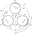
图3是根据示例性实施方式的幻影发动机的俯视图的示意图;3 is a schematic diagram of a top view of a Phantom engine according to an exemplary embodiment;
图4是根据示例性实施方式的幻影发动机的一部分的截面图的示意图;4 is a schematic diagram of a cross-sectional view of a portion of a Phantom engine according to an exemplary embodiment;
图5是示出了根据示例性实施方式的发射磁场的发射频率对时间的曲线图的示意图;5 is a schematic diagram illustrating a graph of transmit frequency versus time of a transmit magnetic field according to an exemplary embodiment;
图6至图8是根据示例性实施方式的幻影发动机中的转子的位置的示意图;6-8 are schematic diagrams of the position of the rotor in a Phantom engine according to an exemplary embodiment;
图9是示出了根据示例性实施方式的随着转子移动的接收线圈的谐振频率的曲线图的示意图;9 is a schematic diagram illustrating a graph of the resonant frequency of the receive coil as the rotor moves, according to an exemplary embodiment;
图10是根据示例性实施方式的用于接收线圈的谐振频率的曲线图的示意图;10 is a schematic diagram of a graph of resonant frequency for a receive coil, according to an exemplary embodiment;
图11是根据示例性实施方式的用于接收线圈的谐振频率的曲线图的示意图;11 is a schematic diagram of a graph of resonant frequency for a receive coil, according to an exemplary embodiment;
图12是示出了根据示例性实施方式的发射磁场的发射频率对时间的曲线图的示意图;12 is a schematic diagram illustrating a graph of transmit frequency versus time of a transmit magnetic field according to an exemplary embodiment;
图13是示出了根据示例性实施方式的用于接收线圈的谐振频率的曲线图的示意图;13 is a schematic diagram illustrating a graph of a resonant frequency for a receive coil according to an exemplary embodiment;
图14是示出了根据示例性实施方式的发射磁场的发射频率对时间的曲线图的示意图;14 is a schematic diagram illustrating a graph of transmit frequency versus time of a transmit magnetic field according to an exemplary embodiment;
图15是示出了根据示例性实施方式的用于接收线圈的谐振频率的曲线图的示意图;15 is a schematic diagram illustrating a graph of the resonant frequency for a receive coil according to an exemplary embodiment;
图16是示出了根据示例性实施方式的用于接收线圈的谐振频率的曲线图的示意图;16 is a schematic diagram illustrating a graph of the resonant frequency for a receive coil according to an exemplary embodiment;
图17是根据示例性实施方式的电动机系统的示意图;17 is a schematic diagram of an electric motor system according to an exemplary embodiment;
图18是根据示例性实施方式的接收线圈至发射线圈的初始定向的示意图;18 is a schematic diagram of an initial orientation of a receive coil to a transmit coil according to an exemplary embodiment;
图19是根据示例性实施方式的用于接收线圈的倾斜定向的示意图;FIG. 19 is a schematic diagram of an oblique orientation for a receive coil, according to an exemplary embodiment;
图20是根据示例性实施方式的幻影发动机的示意图;20 is a schematic diagram of a Phantom Engine according to an exemplary embodiment;
图21是示出了根据示例性实施方式的发射磁场的生成的流程图的示意图;21 is a schematic diagram illustrating a flow diagram of the generation of a transmit magnetic field according to an exemplary embodiment;
图22是示出了根据示例性实施方式的电动机的操作的流程图的示意图;22 is a schematic diagram illustrating a flow chart of the operation of an electric motor according to an exemplary embodiment;
图23是根据示例性实施方式的用于识别转子和电动机的位置的过程的流程图的示意图;并且FIG. 23 is a schematic diagram of a flowchart of a process for identifying the position of the rotor and electric motor according to an exemplary embodiment; and
图24是根据示例性实施方式的用于使接收线圈中的轴线对准(alignment)的过程的流程图的示意图。24 is a schematic illustration of a flow diagram of a process for aligning axes in a receive coil, according to an exemplary embodiment.
具体实施方式Detailed ways
示例性实施方式识别并且考虑一个或多个不同的考虑因素。例如,示例性实施方式识别并且考虑其中幻影发动机系统的成本、重量或者尺寸中的至少一个减少的一个方式以减少线圈数量的方式设计幻影发动机系统。例如,示例性实施方式识别并且考虑其中可以减少这些参数的一个方式是使用幻影发动机系统在幻影发动机系统的发动机部分中的定子上减少需要对准通过具有发射线圈与接收线圈生成的外场的发射线圈的数量。当前使用的幻影发动机系统具有三个发射线圈。Exemplary embodiments identify and take into account one or more different considerations. For example, exemplary embodiments identify and design the Phantom engine system in a manner that reduces the number of coils in consideration of one way in which at least one of cost, weight, or size of the Phantom engine system is reduced. For example, exemplary embodiments identify and consider one way in which these parameters can be reduced is to use a phantom motor system on the stator in the motor portion of the phantom motor system to reduce the need to align the transmit coils with the external field generated by the transmit coils and the receive coils quantity. The currently used Phantom engine system has three transmit coils.
因此,示例性实施方式提供了用于发动机系统的方法和设备。在一个示例性实例中,设备包括发射器和无线电动机。具体地,无线电动机可以是幻影发动机。Accordingly, the exemplary embodiments provide methods and apparatus for engine systems. In one illustrative example, the device includes a transmitter and a wireless motor. Specifically, the wireless motor may be a phantom motor.
例如,其中发射线圈的数量可减少的一个方式是通过选择用于发动机上的定子的接收线圈的定向。例如,接收线圈可从转子的旋转轴进行放射状布置。换言之,可安置线圈使得通过线圈延伸的轴基本上垂直于转子的转子轴。示例性实施方式识别并且考虑接收线圈的这类定向,可使用单个发射线圈。发射线圈可具有与旋转轴平行的定向。For example, one way in which the number of transmit coils can be reduced is by choosing the orientation of the receive coils for the stator on the engine. For example, the receiving coils may be arranged radially from the axis of rotation of the rotor. In other words, the coils may be positioned such that the axis extending through the coils is substantially perpendicular to the rotor axis of the rotor. Exemplary embodiments recognize and take into account such orientations of the receive coils that a single transmit coil may be used. The transmit coil may have an orientation parallel to the axis of rotation.
在另一示例性实例中,电动机可具有转子和一组接收线圈。该转子关于转子轴旋转,并且该转子由磁性材料组成。该一组接收线圈具有基本上平行于转子轴而定位的一组轴线。接收线圈具有用于该一组线圈的一组谐振频率。在示例性实例中,当发射磁场具有与线圈的谐振频率相关的选定频率时,该一组线圈中的线圈具有来自该一组线圈中的其他线圈的不同谐振频率,使得该线圈生成吸引转子的接收磁场。如本文中使用的,当参考项目使用“一组”时表示一个或多个项目。例如,一组接收线圈是一个或多个接收线圈。In another illustrative example, an electric motor may have a rotor and a set of receiving coils. The rotor rotates about the rotor axis, and the rotor is composed of magnetic material. The set of receive coils has a set of axes positioned substantially parallel to the rotor axis. The receiving coil has a set of resonant frequencies for the set of coils. In an illustrative example, when the transmit magnetic field has a selected frequency related to the resonant frequency of the coils, the coils in the set have different resonant frequencies from other coils in the set, such that the coils generate an attraction to the rotor the receiving magnetic field. As used herein, when referring to an item as "a group" it means one or more items. For example, a set of receive coils is one or more receive coils.
在示例性实例中,选择相对于发射线圈的不同定位的接收线圈,使得接收线圈的轴线基本上平行于通过发射线圈生成的发射磁场中的磁场线而定位。以这种方式,可选择接收线圈的定向来增加从发射线圈无线接收电力的电动机的效率。In an illustrative example, the different positioning of the receive coils relative to the transmit coils is selected such that the axes of the receive coils are located substantially parallel to the magnetic field lines in the transmit magnetic field generated by the transmit coils. In this way, the orientation of the receiving coils can be selected to increase the efficiency of the motor that wirelessly receives power from the transmitting coils.
参考附图并且具体地参考图1,根据示例性实施方式描述了电动机系统环境的框图的示意图。在此示例性实例中,电动机系统环境100包括电动机系统102。Referring to the drawings and in particular to FIG. 1 , a schematic diagram of a block diagram of an electric motor system environment is depicted in accordance with an exemplary embodiment. In this illustrative example,
电动机系统102可与平台(platform)104相关联。当一个部件与另一个部件“相关联”时,该关联在所描述的实例中是物理关联。例如,第一部件可被认为通过固定至第二部件、结合至第二部件、安装至第二部件、焊接至第二部件、紧固至第二部件或以一些其他适当的方式连接至第二部件中的至少一个来与第二部件在物理上相关联。第一部件还可以使用第三部件连接至第二部件。第一部件还可以被认为是通过形成为第二部件的部分、第二部件的延伸或者两者而与第二部件在物理上相关联。The
在此示例性实例中,平台104可以采用各种形式。例如,平台104可以选自移动平台、固定平台、陆上结构(land-based stucture)、水上结构(aquatic-based stucture)和空中结构(space-based structure)中的一个。更具体地,该平台可以是飞机、无人驾驶飞行器、无人驾驶的陆上车辆、水面舰艇、坦克、人员输送车、火车、航天器、空间站、卫星、潜水艇、汽车、发电厂、桥梁、水坝、房屋、制造设施、建筑物、假肢、人造器官、可植入药泵(implantable drug pump)、生物医学植入物、机械臂和纳米机器人以及其他合适的平台。In this illustrative example,
如所描述的,电动机系统102包括控制器106和电动机108。在示例性实例中,电动机系统102可以是幻影发动机系统110,其中,电动机108是幻影发动机112。如所描述的,当电动机108采用幻影发动机112的形式时,将电力无线发送至幻影发动机112。换言之,幻影发动机112不具有供应用于操作幻影发动机112的电力的电力电缆或者配线。As depicted,
在示例性实例中,控制器106包括发射器114。如所描述的,发射器114控制电动机108的操作。例如,发射器114包括以发射磁场118的形式供应电力的发射线圈116。In the illustrative example,
如所描述的,电动机108由多个不同的部件构成。在示例性实例中,电动机108包括转子120、一组接收线圈122、一组电容器124以及壳体126。As described, the motor 108 is constructed from a number of different components. In the illustrative example, motor 108 includes
转子120围绕转子轴128旋转。转子120由磁性材料130组成。在示例性实例中,磁性材料130可以是生成磁场的任何材料。响应于外加磁场而出现通过磁性材料130生成的磁场。
在示例性实例中,该一组接收线圈122具有一组轴线132。如所描述的,该一组轴线132被定向为基本上平行于转子轴128。该一组接收线圈122具有一组谐振频率134。In the illustrative example, the set of receive
如所描述的,该一组电容器124电连接至该一组接收线圈122。当该一组电容器124连接至该一组接收线圈122时,该一组电容器124设置用于该一组接收线圈122的该一组谐振频率134。在示例性实例中,当接收线圈描述为具有谐振频率时,该描述意味着接收线圈和连接至接收线圈的电容器形成具有谐振频率的电路。As depicted, the set of
该一组电容器124可具有不同值,使得该一组接收线圈122具有用于该一组谐振频率134的不同值。例如,该一组接收线圈122中的接收线圈136具有不同于该一组接收线圈122中的其他接收线圈的该一组谐振频率134中的谐振频率138。换言之,接收线圈136与电容器140形成具有谐振频率138的电路。The set of
在一个示例性实例中,该一组谐振频率134中的每一个都是唯一的。换言之,该一组谐振频率134中没有一个具有与该一组谐振频率134中的其他谐振频率相同的值。In one illustrative example, each of the set of
如所描述的,该一组接收线圈122中的接收线圈136电连接至该一组电容器124中的电容器140。在此示例性实例中,接收线圈136和电容器140形成电感电路,使得接收线圈136具有谐振频率138。电感电路是LC电路。在示例性实例中,谐振频率138是其中围绕由接收线圈136和电容器140形成的LC电路的阻抗约为零的频率。As depicted, the receive
在此示例性实例中,当发射磁场118具有与接收线圈136的谐振频率138相关的选定频率144时,接收线圈136生成吸引转子120的接收磁场142。换言之,接收磁场142吸引转子120的使转子120旋转的部分,使得转子120的该部分朝向接收线圈136移动。In this illustrative example, when transmit
具有选定频率144的发射磁场118可具有生成接收磁场142的幅值(magnitude)。具体地,发射磁场118的选定频率144可以是生成接收线圈136中的接收磁场142的谐振频率138。选定频率144可具有与谐振频率138相同的值。The transmit
在示例性实例中,谐振频率138是通过接收线圈136生成的接收磁场142足以吸引该示例性实例中的转子120的频率。在示例性实例中,这个引力可意指转子120朝向接收线圈136移动。换言之,当转子120旋转时,接收线圈136是固定的并且不能转动。换言之,转子120围绕转子轴128是可旋转的并且该一组接收线圈122具有固定位置。在这个所描述的实例中,该一组接收线圈122是电动机108中的定子145的一部分。具有选定频率144的发射磁场118可具有生成接收磁场142的幅值。具体地,发射磁场118的选定频率144可以是生成接收线圈136中的接收磁场142的谐振频率138。In the illustrative example,
以这种方式,可以激活不同的接收线圈122以生成包括接收磁场142的该一组接收磁场146。该一组接收磁场146的生成可使得转子120以期望的速度在所期望的方向上移动。该一组接收磁场146的生成还可导致转子120具有期望的转矩(torque)。In this manner, different receive
在一个示例性实例中,可同时激活该一组接收线圈122中的不止一个的接收线圈以同时生成接收磁场146。当不止一个接收线圈122同时生成接收磁场146时,这些频率的接收磁场146可具有不同的幅值。In one illustrative example, more than one receive coil of the set of receive
在此示例性实例中,用于发射磁场118的发射频率148可以改变,使得该一组接收线圈122中所有的接收线圈被激活并且生成该一组接收磁场146。随着时间的过去改变发射频率148,使得发射频率148等于在循环150中出现的该一组谐振频率134中所有的谐振频率。具体地,循环150是发射频率148改变为激活该一组接收线圈122以生成该一组接收磁场146的时间周期。In this illustrative example, transmit
如所描述的,壳体126是保持电动机108中的部件的结构。在示例性实例中,转子120、该一组接收线圈122或者该一组电容器124中的至少一个位于壳体126内部。在此示例性实例中,发射器114位于壳体126的外部。As described, the
此外,电动机系统102可包括倾斜调整系统160。倾斜调整系统160是改变该一组接收线圈122的定向的装置。以这种方式,可改变该一组轴线132的定向。该一组轴线132的定向的变化可以基于从发射磁场118中的磁场线164的该一组轴线132的发散的量。可在电动机108的操作期间、在电动机108的操作之前、在电动机108的操作之后、或者它们的组合中执行该一组轴线132的对准。可改变定向以获得响应于操作条件的变化的所期望的水平的电动机108的性能。Additionally, the
在此示例性实例中,倾斜调整系统160可包括该一组接收线圈122可移动连接的安装系统166。此外,当倾斜调整系统160积极改变该一组接收线圈122的定向时,倾斜调整系统160还可包括传感器系统168,以检测具有该一组接收线圈122的该一组轴线132的发射磁场118中的磁场线164的对准。此外,倾斜调整系统160还可包括致动器系统170,以改变该一组接收线圈122的定向,从而使该一组轴线132改变该定向。In this illustrative example, tilt adjustment system 160 may include mounting
如果被动执行该一组轴线132的定向的调整,则在电动机108中不需要传感器系统168和致动器系统170。反而,该一组接收线圈122可通过响应于发射磁场118与该一组接收线圈122的相互作用而在安装系统166上移动,从而改变它们的定向。If the adjustment of the orientation of the set of
图1中的电动机系统环境100的示意图并不意指暗示对可以实施示例性实施方式的方式进行物理或者结构的限制。可以使用除了示出的部件之外的或者代替示出的部件的其他部件。一些部件可能不是必需的。此外,呈现的框示出了一些功能性部件。当在示例性实施方式中实施时,这些框的一个或多个可以组合、分离或组合和分离成不同的框。The schematic diagram of electric
例如,控制器106包含发射器114。尽管未示出,但是控制器106还可包括生成用于发射器114的电力的电源。控制器106除了发射器114之外还可包括其他发射器或者还可包括其他发射器来代替发射器114。如另一实例,在电动机系统102中除了电动机108之外的可以使用一个或多个电动机或者可以使用一个或多个电动机来代替电动机108。在另一示例性实例中,转子120的引力可意指接收线圈136朝向转子120移动而不是转子120旋转。换言之,在一些说明性实例中,接收线圈136可围绕转子轴128旋转而同时转子120被固定并且不能转动。For example,
现在参照图2,根据示例性实施方式描述了幻影发动机的示意图。在这个所描述的实例中,在等轴视图(isometric view)中示出了幻影发动机200。幻影发动机200是图1中以方框形式示出的幻影发动机112的实现实例。Referring now to FIG. 2 , a schematic diagram of a Phantom Engine is depicted in accordance with an exemplary embodiment. In this described example, the
如所描述的,幻影发动机200具有三个接收线圈:接收线圈A 202、接收线圈B 204以及接收线圈C 206。在此示例性实例中,转子208位于壳体210内部。在此示例性实例中,在幻影发动机中示出了转子208。As depicted, the
壳体210可由非导电材料组成。壳体210使用非导电材料可以减少任何电流,该电流可以减少或者防止振荡磁场到达接收线圈A 202、接收线圈B 204以及接收线圈C 206。The
在示例性实例中,转子208围绕转子轴212旋转。如所描述的,接收线圈A 202具有轴214;接收线圈B 204具有轴216;并且接收线圈C 206具有轴218。用于接收线圈的轴线通过相应的接收线圈在中心延伸。在此示例性实例中,每个接收线圈具有缠绕形成气缸的配线或者金属线,该气缸具有通过这个描述的实例中的气缸在中心延伸的轴。在其他示例性实例中,线圈可具有除了气缸之外的其他形状。In the illustrative example,
轴214、轴216和轴218被定向为基本上平行于转子轴212。进一步地,轴214、轴216和轴218被定向为基本上彼此平行。
另外,在此示例性实例中,各个接收线圈具有两个部分。如所描述的,接收线圈A202具有第一部分220和第二部分(未示出);接收线圈B 204具有第一部分224和第二部分226;并且接收线圈C 206具有第一部分228和第二部分230。Additionally, in this illustrative example, each receive coil has two sections. As depicted, receive
如所描述的,接收线圈A 202的第一部分220、接收线圈B 204的第一部分224以及接收线圈C 206的第一部分228位于转子208的第一侧232上。接收线圈A 202的第二部分(未示出)、接收线圈B 204的第二部分226以及接收线圈C 206的第二部分230位于转子208的第二侧234上。As depicted,
更具体地,接收线圈A 202的第一部分220、接收线圈B 204的第一部分224以及接收线圈C 206的第一部分228位于由包含转子208的壳体210所定义的体积(volume)的第一侧上。以类似方式,接收线圈A 202的第二部分(未示出)、接收线圈B 204的第二部分226以及接收线圈C 206的第二部分230位于由壳体210定义的体积的第二侧上。以这种方式,接收线圈的第一部分和第二部分位于彼此相对的位置,但是与通过接收线圈延伸的轴线对齐。More specifically,
在示例性实例中,电容器连接至接收线圈。如所描述的,接收线圈A202具有电容器A(未示出);接收线圈B 204具有电容器B 242,并且接收线圈C 206具有电容器C 244。这些电容器设置用于每一个线圈的谐振频率。如所描述的,在所描述的实例中,电容器具有不同值,使得每个线圈的谐振频率值不同于其他线圈的谐振频率值。In the illustrative example, the capacitor is connected to the receiving coil. As depicted, receive
在此示例性实例中,这些接收线圈通过平行的磁场矢量通电(energized):磁场矢量236用于接收线圈A 202,磁场矢量238用于接收线圈B 204以及磁场矢量240用于接收线圈C 206。这些磁场矢量通过发射线圈(未示出)生成并且使相应的接收线圈生成磁场。以这种方式,幻影发动机200无线地提供电力。In this illustrative example, the receive coils are energized by parallel magnetic field vectors:
接下来参考图3,根据示例性实施方式描述了幻影发动机的俯视图。在本附图中,示出了沿着图2中的3-3方向截取的视图中的幻影发动机200的俯视图。Referring next to FIG. 3 , a top view of a Phantom Engine is depicted in accordance with an exemplary embodiment. In this figure, a top view of the
在这个视图中,转子208被描述为具有第一端300和第二端302的延伸形状的两末端转子(two ended rotor)。在该视图中还看到的是连接至接收线圈A 202的电容器A 304。In this view,
接下来参考图4,根据示例性实施方式描述了幻影发动机的一部分的截面图的俯视图。在这个所描述的实例中,看到的是沿着图3中的线4-4所截取的幻影发动机200的一部分的截面图。Referring next to FIG. 4 , a top view of a cross-sectional view of a portion of a Phantom Engine is depicted in accordance with an exemplary embodiment. In this depicted example, a cross-sectional view of a portion of
在这个视图中,示出了接收线圈A 202的第二部分400。参照转子208定位第一部分220使得存在空气间隙402。参照转子208定位接收线圈A202的第二部分400使得存在空气间隙404。空气间隙402和空气间隙404是由壳体210定义的体积的一部分。换言之,在示例性实例中,接收线圈A 202不接触转子208。在示例性实例中,可以使空气间隙402和空气间隙404尽可能的小。In this view, the
另外,通过配线406将第一部分220连接至第二部分400。通过电容器A 304将第一部分220连接至第二部分400来完成该电路。如所描述的,电容器A 304与接收线圈A 202的第一部分220和第二部分400串联连接。根据特定实施方法,第一部分220与第二部分400可以具有相同的匝数或者不同的匝数。In addition, the
当接收线圈A 202通电时,接收线圈A 202生成磁场,该磁场将转子208吸引到位于接收线圈A 202的第一部分220和第二部分400之间的空气间隙402和空气间隙404之间的体积中。该体积可被称为转子体积。如所描述的,接收线圈A 202的通电由来自发射器(未示出)中的发射线圈的磁场所引起。When the receive
接下来参考图5,示出了根据示例性实施方式所描述的用于发射磁场的发射频率对时间的曲线图的示意图。如所描述的,曲线图500示出了通过发射线圈生成的发射磁场的发射频率,诸如通过以图1中的方框形式示出的由发射线圈116生成的发射磁场118。Referring next to FIG. 5, a schematic diagram of a graph of transmit frequency versus time for transmitting a magnetic field is shown, according to an exemplary embodiment. As depicted,
在此示例性实例中,曲线图500在y轴502上示出了发射频率以及在x轴504上示出了时间。y轴502上的发射频率表示使图2中的接收线圈A 202、接收线圈B 204以及接收线圈C 206生成磁场的频率。x轴504上的时间表示转子转动的周期。在此示例性实例中,x轴504上的每一个单元表示转子的一个旋转的时间,其是通过频率范围的两个循环。In this illustrative example,
如所描述的,ΦA频段506是接收线圈A 202变成通电并且生成磁场的频率范围。ΦB频段508是接收线圈B 204变成通电并且生成磁场的频率范围,并且ΦC频段510是接收线圈C 206变成通电并且生成磁场的频率范围。As depicted, the
在示例性实例中,发射磁场的谐振频率随着图2至图4中示出的转子208转动而变化。该变化使转子208旋转,这也称为交换(commutation)。In the illustrative example, the resonant frequency of the transmitted magnetic field varies as the
尽管通过发射线圈生成的磁场平行于线圈的所有的三个轴线,但是只有具有接收线圈的频带内的选定频率的接收线圈能生成磁场。通过接收线圈生成的磁场随着频率发射磁场接近接收线圈的谐振频率而增加,并且随着频率远离接收线圈的谐振频率移动而减少。Although the magnetic fields generated by the transmit coils are parallel to all three axes of the coils, only receive coils with selected frequencies within the frequency band of the receive coils can generate magnetic fields. The magnetic field generated by the receiving coil increases as the frequency of the transmitting magnetic field approaches the resonant frequency of the receiving coil and decreases as the frequency moves away from the resonant frequency of the receiving coil.
在这个实例中,线512表示通过发射线圈生成的磁场的频率,发射线圈是用于具有ABC相序的序列的转子208的旋转。在这个描述的实例中,A表示接收线圈A 202,B表示接收线圈B 204,以及C表示接收线圈C 206。In this example,
可重复发射线圈的传输图案以使转子208沿着CBA的方向移动。该移动可与角频率一起发生,角频率是像其中接收线圈被磁化为生成磁场的序列那样快的二分之一。例如,当在ABCABC的序列中磁化接收线圈时,转子208的端部与接收线圈对齐为如下:第一端300与A对齐,第二端302与B对齐,第二端302与A对齐,第一端300与B对齐,并且第二端302与C对齐。该序列完成转子208的一个旋转。在这个实例中,转子208的第一端300随着序列ACB,该序列ACB是其中磁化这个实例中的线圈的序列的反方向。The transmission pattern of the transmit coils can be repeated to move the
接下来转至图6至图8,根据示例性实施方式描述了幻影发动机中的转子的位置的示意图。在图6中,根据示例性实施方式描述了转子的开始位置。在图6中,在线圈被激活生成磁场之前的开始位置中示出了转子208。Turning next to FIGS. 6-8 , schematic diagrams of the location of rotors in a Phantom engine are depicted in accordance with an exemplary embodiment. In Figure 6, the starting position of the rotor is depicted according to an exemplary embodiment. In Figure 6, the
在示例性实例中,θ是转子208的位置。在初始位置中,θ等于0度并且转子208的第二端302直接与接收线圈A 202对齐。如所描述的,转子208沿着箭头600的方向旋转。如所描述的,箭头600表示转子208运转的角速度(ωrotor)。这个速度可用弧度每秒表示。In the illustrative example, θ is the position of
接下来在图7中,根据示例性实施方式描述了幻影发动机中的转子的另一个位置。在本图中,转子208进一步沿着箭头600的方向移动,到达θ等于20度的位置。第二端302远离接收线圈A 202移动。Next in FIG. 7, another position of the rotor in the Phantom engine is depicted according to an exemplary embodiment. In this figure,
在图8中,根据示例性实施方式描述了幻影发动机中的转子的另一个位置。如所描述的,转子208更进一步沿着箭头600的方向移动,到达θ等于90度的位置。在这个位置中,第二端302移动90度远离接收线圈A 202四分之一转。关于转子208的四分之一旋转,转子208与接收线圈A 202最不对准。In FIG. 8, another position of the rotor in a phantom engine is depicted according to an exemplary embodiment. As depicted,
在本视图中,第二端302更远离接收线圈A 202移动。与第二端302远离线圈A 202移动一样,第一端300朝向接收线圈A 202移动。In this view, the
在示例性实例中,尽管由与每个接收线圈相关联的电容器设置谐振频率,但是转子208的移动可改变接收线圈的谐振频率。换言之,为从线圈和电容器的接收线圈设置的谐振频率随着转子208相对于接收线圈的移动而变化。In the illustrative example, although the resonant frequency is set by a capacitor associated with each receive coil, movement of
接下来参考图9,示出了根据示例性实施方式描述的随着转子移动的接收线圈的谐振频率的曲线图的示意图。如所描述的,曲线图902中的x轴900表示用度数表示的转子208的转子位置θ,并且y轴904表示谐振频率。Referring next to FIG. 9 , a schematic diagram of a graph of the resonant frequency of the receive coil as the rotor moves, described in accordance with an exemplary embodiment, is shown. As depicted, the
在示例性实例中,ΦA是接收线圈A 202的谐振频率,ΦB是接收线圈B 204的谐振频率,并且ΦC是接收线圈C 206的谐振频率。在此示例性实例中,线906表示接收线圈A 202的谐振频率(ΦA)。线908表示接收线圈B 204的谐振频率(ΦB),并且线910表示接收线圈C206的谐振频率(ΦC)。In the illustrative example, ΦA is the resonant frequency of receive
如在曲线图902中可以看出的,根据转子208的位置改变每一个接收线圈的谐振频率。换言之,随着转子208改变并且移动至不同的位置,每一个接收线圈的谐振频率改变。As can be seen in
当转子208具有θ=90度的位置时转子208中的铁磁性材料最远离接收线圈A 202,并且接收线圈A 202的磁性电感L具有最小值。当θ=90度时,由ω=(LC)-1/2给出的线906中的谐振频率ΦA是最高的。The ferromagnetic material in the
随着转子208朝向接收线圈A 202移动,接收线圈A 202的电感L增加并且线906中的ΦA下降。在θ=180度处,当转子208最靠近线圈A 202时,电感达到最大值并且ΦA达到最小值。如所示,随着转子208朝向θ=270度移动越过接收线圈A 202,线906中的ΦA再次上升。As
在示例性实例中,接收线圈B 204连接至电容器,该电容器大于接收线圈A 202的电容器。因此,接收线圈B 204的线908中的ΦB以小于接收线圈A 202的线906中的ΦA的谐振频率范围操作。因为接收线圈B 204从接收线圈A 202位于120度并且转子208具有两个端,线908中的ΦB的上升和下降以转子208的运转60度滞后于线906中的ΦA。In the illustrative example, receive
如所描述的,接收线圈C 206连接至电容器,该电容器大于接收线圈A 202和接收线圈B 204的电容器。因此,接收线圈C 206的ΦC具有三个接收线圈的谐振频率的最低范围。线910中的ΦC的上升和下降以120度滞后于线906中的ΦA。As depicted, receive
接下来转至图10,根据示例性实施方式描述了用于接收线圈的谐振频率的曲线图的示意图。在本图中,曲线图1000表示根据关于发射频率的转子位置的谐振频率。如所描述的,x轴1002表示用度数表示的转子208的转子位置θ,并且y轴1004表示谐振频率。Turning next to FIG. 10 , a schematic diagram of a graph of the resonant frequency for a receive coil is depicted in accordance with an exemplary embodiment. In this figure,
在所描述的实例中,线1006表示接收线圈A 202的谐振频率(ΦA),线1008表示接收线圈B 204的谐振频率(ΦB),以及线1010表示接收线圈C 206的谐振频率(ΦC)。线1012表示通过发射线圈在转子208的不同位置生成的发射磁场的频率。发射线圈的频率也称为发射频率。In the depicted example,
在此示图中,发射频率的变化使得转子208旋转。在这个所描述的实例中,启动循环是ABC。In this illustration, the change in transmit frequency causes
当接收线圈被激活时,接收线圈生成磁场。接收线圈从发射器接收能量并且将能量转换为生成接收磁场的电流。接收磁场朝向接收线圈吸引转子208。When the receiver coil is activated, the receiver coil generates a magnetic field. The receive coil receives energy from the transmitter and converts the energy into electrical current that generates a receive magnetic field. The receiving magnetic field attracts the
例如,利用接收线圈A 202,接收线圈A 202激活生成接收磁场,这使得转子208吸引至更靠近的θ=0度或者θ=180度。For example, with receive
在另一示例性实例中,发射器不了解转子208的转子位置。如线1012的时间t01014所示,发射器开始从具有发射频率的发射线圈以接收线圈A 202的最高可能的谐振频率发射发射磁场。In another illustrative example, the transmitter has no knowledge of the rotor position of
如线1012中所描述的,发射频率然后下降。在时间t11016时,线1012中的发射频率达到对应于转子208的当前位置θ的线圈A 202的谐振频率。在曲线图1000中,θ约为140度。As depicted in
在接收线圈A 202的谐振频率处,接收线圈A 202变成通电并且开始吸引转子208。随着转子208更靠近于接收线圈A 202移动,接收线圈A 202的谐振频率减少。只要幻影发动机200上的负载不超过转子转矩,转子208足够快速的朝向接收线圈A 202移动以保证接收线圈A 202的谐振频率以与发射频率相同的速率减少。At the resonant frequency of receive
在时间t21018时,线1012中的发射频率达到接收线圈A 202最低可能的谐振频率。同时,转子208变成与线圈A 202对齐,其中,转子208具有θ=180度的位置。At
发射频率继续下降并且不再匹配接收线圈A 202的谐振频率。因此,接收线圈A202断开并且不再生成接收磁场。现在发射频率匹配接收线圈B 204的谐振频率。接收线圈B204变成激活的并且生成吸引转子208的接收磁场。转子208朝向最靠近接收线圈B 204的位置的θ=240度移动。The transmit frequency continues to drop and no longer matches the resonant frequency of receive
在曲线图1000中的时间t31020时,线1012中示出的发射频率达到接收线圈B 204最低可能的谐振频率。同时,转子208变成与接收线圈B 204对齐。转子208在θ=240度处。如线1012所示,发射频率继续下降。接收线圈B 204断开并且不生成磁场。At
现在发射频率匹配接收线圈C 206的谐振频率。因此,接收线圈C 206变成激活的并且转子208被吸引到接收线圈C 206的最靠近的位置。转子208朝向θ=300度移动。The transmit frequency now matches the resonant frequency of the receive
在时间t41022时,线1012中的发射频率达到接收线圈C 206的最低可能的谐振频率。同时,转子208达到与线圈C 206对齐,其中,转子208在θ=300度处。At
在时间t41022时,发射器将发射频率转换至靠近接收线圈A 202的谐振频率范围的上端。接收线圈C 206断开并且接收线圈A 202变成激活的。现在转子208被吸引到接收线圈A 202的下一位置,其是转子208的θ=360度。当到达时间t5 1024时,然后重复该循环。At
现在转至图11,根据示例性实施方式描述了用于接收线圈的谐振频率的曲线图的示意图。在本图中,曲线图1100表示根据关于发射频率的转子位置的谐振频率。如所描述的,x轴1102表示用度数表示的转子208的转子位置θ,并且y轴1104表示谐振频率。Turning now to FIG. 11 , a schematic diagram of a graph of the resonant frequency for a receive coil is depicted in accordance with an exemplary embodiment. In this figure,
在所描述的实例中,线1106表示接收线圈A 202的谐振频率(ΦA),线1108表示接收线圈B 204的谐振频率(ΦB),以及线1110表示接收线圈C 206的谐振频率(ΦC)。线1112表示通过发射线圈在转子208的不同位置生成的发射磁场的发射频率。In the depicted example, line 1106 represents the resonant frequency (ΦA) of receive
曲线图1100表示当转子208的初始位置θ在接收线圈A 202的位置的稍前方时的启动循环。在这个实例中,如线1112所示,发射频率在时间t01114时以接收线圈A 202的最高可能的谐振频率开始并且减少。在时间t11116时,发射频率匹配接收线圈A 202的当前谐振频率。
在这个实例中,转子208具有θ=220度的位置。因此,转子208最初朝向接收线圈A202至θ=180度向后吸引。In this example,
在时间t21118时,如线1112所示的发射频率达到接收线圈A 202最低可能的谐振频率。同样在时间t21118时,转子208达到与接收线圈A 202对齐并且在θ=180度处。At
线1112中的发射频率继续下降并且不再匹配接收线圈A 202的谐振频率。因此,接收线圈A 202断开并且不再生成接收磁场。The transmit frequency in
发射磁场的发射频率现在匹配接收线圈B 204的谐振频率。接收线圈B 204变成激活的,并且转子208被吸引到接收线圈B最靠近的位置,这是转子208的θ=240度。如所描述的,θ=240度数是从转子208的当前位置向前的位置。因此,如图6所示,转子208停止最初的向后移动并且开始沿着箭头600的方向向前移动。本实例中的向后移动是转子208沿着转子208的所希望的移动的相反方向的移动。The transmit frequency of the transmit magnetic field now matches the resonant frequency of the receive
随后,如图5所示,转子208向前移动,并且发射频率继续从高到低循环,然后跳回高频率。例如,在时间t31120时,接收线圈B 204停用并且接收线圈C 206激活。在时间t41122时,发射频率跃变,使得接收线圈C 206停用并且接收线圈A 202激活,其中,该循环在时间t51124时结束。Subsequently, as shown in Figure 5, the
现在转至图12,示出了根据示例性实施方式所描述的用于发射磁场的发射频率对时间的曲线图的示意图。如所描述的,曲线图1200表示通过发射线圈生成的发射磁场的发射频率。Turning now to FIG. 12, a schematic diagram of a graph of transmit frequency versus time for transmitting a magnetic field is shown, according to an exemplary embodiment. As depicted,
在此示例性实例中,曲线图1200在y轴1202上描述了发射频率以及在x轴1204上描述了时间。y轴1202上的发射频率表示使接收线圈A 202、接收线圈B 204以及接收线圈C206生成磁场的频率。x轴1204上的时间表示转子转动的周期。In this illustrative example,
如所描述的,ΦA频段1206是接收线圈A 202变成通电并且生成磁场的频率范围。在这个实例中,ΦB频段1208是接收线圈B 204变成通电并且生成磁场的频率范围,并且ΦC频段1210是接收线圈C 206变成通电并且生成磁场的频率范围。As depicted, the
如所描述的,线1212表示通过转子208的发射线圈生成的磁场的频率。线1212中的发射频率变化的方式表示发射频率中的跳转并且比图5中的发射频率的线512更复杂。与图5中的线512中的发射频率相比,线1212中示出的发射频率导致幻影发动机200更高效的操作。不用于转动转子208或者使转子208逆向运动的发射频率使用以下面的线1212的发射频率减少。As depicted,
现在转至图13,示出了根据示例性实施方式描述的用于接收线圈的谐振频率的曲线图的示意图。在本图中,曲线图1300表示根据关于发射频率的转子位置的谐振频率。如所描述的,x轴1302表示用度数表示的转子208的转子位置θ,并且y轴1304表示谐振频率。Turning now to FIG. 13 , a schematic diagram of a graph of the resonant frequency for a receive coil is shown in accordance with an exemplary embodiment. In this figure,
在所描述的实例中,线1306表示接收线圈A 202的谐振频率(ΦA),线1308表示接收线圈B 204的谐振频率(ΦB),以及线1310表示接收线圈C 206的谐振频率(ΦC)。线1312表示通过发射线圈在转子208的不同位置生成的发射磁场的发射频率。In the depicted example,
在曲线图1300上,线1312具有如图12中的线1212示出的相同的频率循环。在此示例性实例中,线1312比图10中的线1012更间断。On
在时间t01314时,发射频率的变化循环开始,该频率超过接收线圈A 202的谐振频率并且在时间t11316时减小到接收线圈A 202的谐振频率。线1312直接从接收线圈A 202在转子208的位置在时间t21318时的θ=180度的最小谐振频率跳至接收线圈B 204在其中θ=180度的转子208的位置的谐振频率。At time t 0 1314 a cycle of change in transmit frequency begins, which exceeds the resonant frequency of receive
在时间t31320时,发射频率下降至接收线圈C 206的谐振频率。在时间t41322时,发射频率增加到接收线圈A 202的谐振频率,其中,在时间t5 1324时该循环是完整的。At
利用线1312中的发射频率的变化,不浪费时间继续使接收线圈A 202生成接收磁场,其中,发射频率接近于接收线圈A 202的谐振频率。反而,接收线圈B 204直接开始吸引转子208向前移动。Using the change in transmit frequency in
同样,线1312中的发射频率从接收线圈B 204的谐振频率到接收线圈C 206的谐振频率的转换在时间t3 1320时直接吸引转子朝向接收线圈C 206移动。发射频率从接收线圈C 206的谐振频率到接收线圈A 202的谐振频率的转换在t4 1322时直接匹配接收线圈A202的实际谐振频率并且生成向前转矩,使转子208朝向接收线圈A 202移动。Likewise, the transition of the transmit frequency in
在图14中,示出了根据示例性实施方式所描述的用于发射磁场的发射频率对时间的曲线图的示意图。在这个所描述的实例中,曲线图1400表示通过发射线圈生成的发射磁场的发射频率。In FIG. 14, a schematic diagram of a graph of transmit frequency versus time for transmitting a magnetic field is shown according to an exemplary embodiment. In this depicted example,
在此示例性实例中,曲线图1400在y轴1402上示出了发射频率以及在x轴1404上示出了时间。y轴1402上的发射频率表示使接收线圈A 202、接收线圈B 204以及接收线圈C206生成磁场的频率。x轴1404上的时间表示转子转动的周期。In this illustrative example,
如所描述的,ΦA频段1406是接收线圈A 202变成通电并且生成磁场的频率范围。在这个实例中,ΦB频段1408是接收线圈B 204变成通电并且生成磁场的频率范围,并且ΦC频段1410是接收线圈C 206变成通电并且生成磁场的频率范围。As depicted, the
上述发射频率的实例为幻影发动机200使用了ABC相位序列。在一些情况下,幻影发动机200可以沿着多于一个方向操作。当幻影发动机200是双向发动机时,可以使用CBA序列。如所描述的,线1412表示使用CBA序列的通过转子208的发射线圈生成的磁场的频率。The above examples of transmit frequencies use an ABC phase sequence for the
如所描述的,在从约0至约0.5转子周期的第一循环中,线1412中的发射频率在接收线圈A 202的最高可能的谐振频率处开始。如果转子208发生脱离与接收线圈A 202的对齐约90度,则该发射频率激活接收线圈A 202。以约0.5转子周期以上开始的随后的循环开始于线1412中的发射频率在对应于与接收线圈B 204对齐的转子202的接收线圈A 202的谐振频率。As depicted, in the first cycle from about 0 to about 0.5 rotor cycles, the transmit frequency in
现在转至图15,示出了根据示例性实施方式描述的用于接收线圈的谐振频率的曲线图的示意图。在本图中,曲线图1500表示根据关于发射频率的转子位置的谐振频率。如所描述的,x轴1502表示用度数表示的转子208的转子位置θ,并且y轴1504表示谐振频率。Turning now to FIG. 15 , a schematic diagram of a graph of the resonant frequency for a receive coil is shown in accordance with an exemplary embodiment. In this figure,
在所描述的实例中,线1506表示接收线圈A 202的谐振频率(ΦA),线1508表示接收线圈B 204的谐振频率(ΦB),以及线1510表示接收线圈C 206的谐振频率(ΦC)。线1512表示通过发射线圈在转子208的不同位置生成的发射磁场的发射频率。In the depicted example,
在曲线图1500上,线1512表示在转子208的不同位置使用发射频率的CBA循环的发射频率。线1512表示在CBA相位序列中移动转子208一周期。On
在线1512中,发射频率从时间t0 1514到时间t1 1516减少。在时间t1 1516时,线1512中的频率匹配接收线圈A 202的谐振频率。在这个实例中,转子208被吸引到接收线圈A202的最近位置,是转子208的θ=180度。In
如在线1512中所示,发射频率继续减少。在时间t2 1518时,线1512中的发射频率达到接收线圈A 202最低可能的谐振频率。As shown in
转子208继续沿着CBA序列的方向移动,线1512中的发射频率跳至接收线圈C 206的谐振频率。最高的谐振频率对应于具有θ=180度的位置的转子208。该发射频率靠近接收线圈C 206的谐振频率范围的上端。The
在示例性实例中,接收线圈C 206变成激活的。转子208被吸引到接收线圈C 206。转子208朝向θ=120度移动。如所描述的,在曲线图1500中,转子208继续被吸引到θ=120度的位置,如线1512中的发射频率从时间t21518至时间t31520下降。在时间t31520时,发射频率达到接收线圈C 206的最低可能的谐振频率。线1512中的发射频率跳至接收线圈B 204的谐振频率,其对应于θ=120度的转子208的位置。该发射频率靠近接收线圈B 204的谐振频率的上端并且接收线圈B 204变成激活的。In the illustrative example, receive
转子208被吸引到最靠近接收线圈B的位置,其是θ=60度的转子208的位置。如在线1512中看到的,随着发射频率从时间t31520至时间t41522下降,转子208继续被吸引到这个位置。在线1512中的时间t41522时,发射频率达到接收线圈B 204的最低可能的谐振频率。The
在时间t41522时的线1512中示出的发射频率跳至对应于θ=60度的位置中的转子208的接收线圈A 202的谐振频率。该发射频率靠近接收线圈A 202的谐振频率的上端。接收线圈A 202变成激活的,并且转子208被吸引到接收线圈A 202的最近的位置,其中,转子208的θ=0度。随着发射频率从线1512中的时间t41522至时间t51524下降,转子208继续被吸引到这个位置。曲线图1500中示出的循环在CBA相位序列中重复。The transmit frequency shown in
现在转至图16,示出了根据示例性实施方式描述的用于接收线圈的谐振频率的曲线图的示意图。在本图中,曲线图1600表示根据关于发射频率的转子位置的谐振频率。如所描述的,x轴1602表示用度数表示的转子208的转子位置θ,并且y轴1604表示谐振频率。Turning now to FIG. 16 , a schematic diagram of a graph of the resonant frequency for a receive coil is shown according to an exemplary embodiment. In this figure,
在所描述的实例中,线1606表示接收线圈A 202的谐振频率(ΦA),线1608表示接收线圈B 204的谐振频率(ΦB),以及线1610表示接收线圈C 206的谐振频率(ΦC)。线1612表示通过发射线圈在转子208的不同位置生成的发射磁场的发射频率。In the depicted example,
在曲线图1600上,线1612表示在转子208的不同位置使用发射频率的CBA循环的发射频率。曲线图1600中的线1612表示倒退的CBA启动循环,其中,转子208在沿着所希望的方向移动之前沿着转子208旋转的所希望的方向的反方向移动。On
图16示出了当最初的转子位置在第一接收线圈A 202位置的稍前方而不是后方时,发射频率的相同序列如何使发动机启动。在此示例性实例中,在从时间t1至时间t2的间隔期间的最初的向后移动之后,转子沿着CBA方向不断移动。Figure 16 shows how the same sequence of transmit frequencies causes the engine to start when the initial rotor position is slightly forward rather than rearward of the first receive
发射频率从时间t01614时约为接收线圈A 202的谐振频率的频率下降至时间t11616时的接收线圈A 202的谐振频率。发射频率从时间t11616至时间t21618减少。在时间t21618时,发射频率下降至接收线圈C 206的谐振频率。从时间t2 1618至时间t3 1620,发射频率减少。The transmit frequency drops from a frequency about the resonant frequency of receive
在时间t31620时,发射频率跳至接收线圈B 204的谐振频率并且直到时间t41622才减少。在时间t41622时,发射频率跳至接收线圈A 202的谐振频率。直到该循环结束的时间t51624发射频率才减少。At
现在参照图17,根据说明性实施方式描述了电动机系统的示意图。如所描述的,电动机系统1700是图1中以方框形式示出的电动机系统102的实现的实例。Referring now to FIG. 17, a schematic diagram of an electric motor system is depicted in accordance with an illustrative embodiment. As depicted,
如所描述的,电动机系统1700包括发射线圈1702和幻影发动机1704。幻影发动机1704可用在有效区域1712和有效区域1714内的任何地方。幻影发动机1704的有效区域是其中通过发射线圈1702生成的发射磁场的向量为通过响应于暴露于发射磁场的接收线圈生成的接收磁场提供期望水平的区域。例如,有效区域1712和有效区域1714可以是其中幻影发动机1704以期望速度、转矩或者其他参数中的至少一个关于幻影发动机1704的操作旋转的任何区域。As depicted,
关于上界距离和下界距离,有效区域1714至发射线圈1702中的每一个有效区域1712具有可接受的转矩脉动的下界。在这个实例中,下界约为任何两个接收线圈之间的距离的两倍。在此示例性实例中,通过由发射线圈形成的磁偶极子的幅值以及接收线圈处需要的最小磁场强度来确定距离上的上界以生成所期望的转矩。磁场强度与磁偶极子的幅值成正比,与从发射线圈的距离的第三电力以及与根据接收线圈的位置和发射线圈的“磁赤道”之间的角度的1和2之间的值的系数成反比。With regard to the upper and lower bound distances, the
幻影发动机1704关于发射线圈1702的定位与当前使用的幻影发动机相比受到较少约束。另外,幻影发动机1704中的接收线圈的定向与当前可用的幻影发动机相比受到较少约束。The positioning of the
幻影发动机1704可用在各种应用中,使得发射线圈可与幻影发动机分开定位。例如,幻影发动机1704可以位于机翼表面上的紧固件安装机器人中。The
可从安置的发射线圈1702将电力发送至幻影发动机1704,使得幻影发动机1704位于有效区域1712或者有效区域1714内。以这种方式,可以避免笨重的电缆及其支撑结构。避免对电缆的需要可增加其中紧固件可安装在机翼上的速度。Power may be sent to the
在一个示例性实例中,幻影发动机1704和发射线圈1702可相对于彼此移动。这些移动可包括幻影发动机1704和发射线圈1702之间的距离和定向的变化。在此示例性实例中,一个或多个另外的发射线圈可用于利用适当的定向生成磁场以向幻影发动机1704提供电力。In one illustrative example,
现在参考图18和图19,根据示例性实施方式描述了调整幻影发动机中的接收线圈的示意图。首先转至图18,根据示例性实施方式描述了接收线圈至发射线圈的初始定向的示意图。Referring now to FIGS. 18 and 19 , schematic diagrams of tuning a receive coil in a phantom engine are depicted in accordance with an exemplary embodiment. Turning first to FIG. 18, a schematic diagram of the initial orientation of the receive coil to the transmit coil is depicted in accordance with an exemplary embodiment.
在此示例性实例中,接收线圈A 1800、接收线圈B 1802、接收线圈C 1804以及发射线圈1806被示出为电动机系统。为了避免使其中可根据示例性实施方式调整接收线圈的方式的说明晦涩,未示出其他部件。In this illustrative example, receive
如所描述的,接收线圈A 1800具有轴1808,接收线圈B 1802具有轴1810,并且接收线圈C 1804具有轴1812。这些轴线示出为基本上平行于转子轴1814。转子轴1814是转子组(未示出)关于其旋转的轴。As depicted, receive
如这个示例性实例所示,通过发射线圈1806生成的发射磁场1816是磁场,但是不为接收线圈提供所期望的电力水平。在此示例性实例中,发射磁场1816具有磁场线1818。磁场线1818基本上不平行于轴1808、轴1810和轴1812。因此,通过接收线圈A 1800、接收线圈B1802和接收线圈C 1804生成的接收磁场可能不像所期望的一样有效。As shown in this illustrative example, the transmit
现在转至图19,根据示例性实施方式描述了用于接收线圈的倾斜定向的示意图。在这个实例中,与图18中的最初定向相比,接收线圈A 1800、接收线圈B 1802和接收线圈C1804被倾斜为提供与发射磁场1816中的磁场线1818更好的对齐。在此示例性实例中,轴1808、轴1810和轴1812基本上不平行于转子轴1814。然而,轴1808、轴1810和轴1812被定位,使得它们基本上平行于磁场线1818。Turning now to FIG. 19 , a schematic diagram for oblique orientation of the receive coil is depicted in accordance with an exemplary embodiment. In this example, receive
例如,轴1808、轴1810和轴1812的角度可以接近于90度或者可等于90度。关于此定向,线圈轴的平均方向平行于转子轴1814。当轴线的角度等于90度时,该方向不可平行。换言之,线圈轴线、轴1808、轴1810和轴1812关于转子轴1814是对称的,并且每个线圈轴与转子轴1814是共面的。For example, the angles of
在示例性实例中,轴1808、轴1810和轴1812中的每一个基本上平行每个接收线圈的位置处的发射磁场1816中的磁场线1818,并且发射磁场1816基本上平行转子(未示出)的位置处的转子轴1814。In the illustrative example, each of
在另一示例性实例中,当接收线圈A 1800、接收线圈B 1802和接收线圈C 1804靠近发射线圈1806的“磁赤道(magnetic equator)”,或者其中从发射线圈1806到接收线圈A1800、接收线圈B 1802和接收线圈C 1804的距离大于任何两个接收线圈之间的距离约两倍时,轴1808、轴1810和轴1812基本上平行于转子轴1814。当接收线圈A 1800、接收线圈B1802和接收线圈C 1804更靠近发射线圈1806时,并且尤其当接收线圈A 1800、接收线圈B1802和接收线圈C 1804接近于发射线圈1806的一个电极或者另一个电极时,轴1808、轴1810和轴1812可具有从图18中示出的定向更大的倾斜。接收线圈的轴1808、轴1810和轴1812的平均方向仍然平行于转子轴1814,并且每个接收线圈的轴与转子轴1814是共面的。In another illustrative example, when receive
在这些示例性实例中,接收线圈A 1800、接收线圈B 1802和接收线圈C 1804的定向可在其中转子转动操作之前、期间或者之后进行改变。定向的变化可被动地或者主动地发生。In these illustrative examples, the orientation of receive
例如,接收线圈A 1800、接收线圈B 1802和接收线圈C 1804可以与允许这些接收线圈响应于发射场1816改变定向的倾斜调整系统相关联。换言之,发射场1816为改变接收线圈A 1800、接收线圈B 1802和接收线圈C 1804的定向提供电力。以这种方式,轴1808、轴1810和轴1812可具有改变为提供电动机的更高效的操作的定向。For example, receive
在另一实例中,接收线圈A 1800、接收线圈B 1802和接收线圈C 1804的定向可通过倾斜调整系统进行积极改变。例如,倾斜调整系统可包括移动接收线圈以改变定向的致动器系统。In another example, the orientation of receive
以这种方式,倾斜调整系统可以是基于该一组轴线从发射场中的场力线的发散量(divergence,散度)来改变这些接收线圈的该一组轴线的定向的倾斜调整系统。In this way, the tilt adjustment system may be a tilt adjustment system that changes the orientation of the set of axes of the receive coils based on the divergence of the set of axes from the field lines in the transmit field.
进一步地,在一些示例性实例中,轴1808、轴1810和轴1812的定向可以不同。换言之,根据磁场线1818如何延伸穿过接收线圈A 1800、接收线圈B 1802和接收线圈C 1804并且分别与轴1808、轴1810和轴1812对齐,轴1808可具有不同于轴1810或者轴1812的定向。Further, in some illustrative examples, the orientation of
接下来转至图20,根据示例性实施方式描述了幻影发动机的示意图。如所描述的,幻影发动机2000是图1中以方框形式示出的幻影发动机112的一个实现的实例。如所描述的,幻影发动机2000包括接收线圈A 2002、接收线圈B 2004和接收线圈C 2006。此外,幻影发动机2000也包括转子2008。Turning next to FIG. 20 , a schematic diagram of a Phantom Engine is depicted in accordance with an exemplary embodiment. As described,
如所描述的,接收线圈A 2002、接收线圈B 2004和接收线圈C 2006不具有如其他实例示出的圆柱形。反而,非圆柱形线圈用于接收线圈A 2002、接收线圈B 2004和接收线圈C 2006。As depicted, receive
这些接收线圈以圆弧或者环状的部分的形式。这个构造以及其他构造可用于为幻影发动机2000制造有效的使用空间。进一步地,接收线圈A 2002、接收线圈B 2004和接收线圈C 2006的圆弧形也可跨越转子2008的运动范围的较大部分。These receiving coils are in the form of circular arcs or annular segments. This configuration, as well as others, can be used to create efficient use of space for the
以这种方式,可发生材料和能量的更有效使用。另外,接收线圈A 2002、接收线圈B2004和接收线圈C 2006的这类形状可以减少幻影发动机2000操作中的转矩脉动。In this way, a more efficient use of materials and energy can occur. Additionally, such shapes of receive
还呈现了其他部件但是在本示意图中未示出。例如,幻影发动机2000还包括电容器、壳体以及在本示意图中未示出的其他部件。转子2008基本上与图6中的转子208具有相同的大小和形状。在这个实例中,从接收线圈A 2002、接收线圈B 2004和接收线圈C 2006的方向看隐藏了转子2008的零件。Other components are also presented but not shown in this schematic. For example,
示出了图2至图20中的幻影发动机的操作的幻影发动机的示意图和曲线图不意在限制可根据示例性实施方式实现的其他幻影发动机的方式。例如,图2和图4示出了在转子208的两侧上具有部分的接收线圈。在其他示例性实例中,这些接收线圈仅可位于转子208的一侧上。以这种方式,可以发生减少成本的幻影发动机200。转子轴、轴承或者转子轴和轴承可被设计成考虑仅可从在转子208的一侧上具有的线圈发生的增加的扭转转矩。The schematic diagrams and graphs of the phantom engine illustrating the operation of the phantom engine in FIGS. 2-20 are not intended to limit the manner in which other phantom engines may be implemented in accordance with exemplary embodiments. For example, FIGS. 2 and 4 show receiving coils with portions on both sides of the
如另一实例,除了这些图中示出的三个接收线圈之外还可使用其他数量的线圈。例如,可以使用四个接收线圈、六个接收线圈或者一些其他数量的接收线圈。As another example, other numbers of coils may be used in addition to the three receive coils shown in these figures. For example, four receive coils, six receive coils, or some other number of receive coils may be used.
另外,控制器可改变其中发射频率改变的循环的周期。以这种方式,可控制发动机的速度。例如,控制器可控制循环的周期,使得当启动电动机时出现速度逐渐增加,以及当停止电动机时速度逐渐降低。进一步地,可以选择发射磁场的幅值以改变幻影发动机200可生成的转矩的量。Additionally, the controller may vary the period of the cycle in which the transmission frequency is changed. In this way, the speed of the engine can be controlled. For example, the controller may control the period of the cycle such that a gradual increase in speed occurs when the motor is started, and a gradual decrease in speed occurs when the motor is stopped. Further, the magnitude of the emitted magnetic field can be selected to vary the amount of torque that the
图2至图4、图6至图8以及图17至图19中示出的不同部件可结合图1中的部件,与图1中的部件一起使用,或者这两者的结合。此外,图2至图4、图6至图8以及图17至图19中的一些部件可以是以图1中的方框形式示出的部件如何可被实现为物理结构的示例性实例。The different components shown in Figures 2-4, 6-8, and 17-19 may be combined with the components of Figure 1, used with the components of Figure 1, or a combination of both. Furthermore, some of the components in FIGS. 2-4, 6-8, and 17-19 may be illustrative examples of how components shown in block form in FIG. 1 may be implemented as physical structures.
不同的示例性实例描述执行动作或操作的部件。在示例性实施方式中,部件被配置为执行所描述的动作或操作。例如,该部件可具有为该部件提供执行在示例性实例中描述为通过该部件可执行的动作或操作的能力的构造或设计。Different illustrative instances describe components that perform actions or operations. In exemplary embodiments, components are configured to perform the described actions or operations. For example, the component may have a construction or design that provides the component with the ability to perform the actions or operations described in the illustrative examples as being executable by the component.
接下来转至图21,根据示例性实施方式描述了示出生成发射磁场的流程图的示意图。图21中示出的过程可在图1中的电动机系统环境100中实现。具体地,图21中示出的不同操作可在图1中的电动机系统102中实现。Turning next to FIG. 21 , a schematic diagram illustrating a flow chart for generating an emission magnetic field is depicted in accordance with an exemplary embodiment. The process shown in FIG. 21 may be implemented in the
通过基于该一组接收线圈的谐振频率选择发射磁场的发射频率来开始该过程(操作2100)。在操作2100中,发射频率可基于接收线圈的谐振频率。The process begins by selecting a transmit frequency of the transmit magnetic field based on the resonant frequencies of the set of receive coils (operation 2100). In
然后,该过程使用选定的发射频率生成发射磁场(操作2102)。在操作2102中,在相对于该一组接收线圈安置的发射线圈处生成具有发射频率的发射磁场。The process then generates a transmit magnetic field using the selected transmit frequency (operation 2102). In
确定发射线圈是否继续生成磁场(操作2104)。如果发射线圈继续生成发射磁场,该过程返回至操作2100。否则,该过程终止。It is determined whether the transmit coil continues to generate a magnetic field (operation 2104). If the transmit coil continues to generate the transmit magnetic field, the process returns to
在图21中,发射频率可变成包含接收线圈的所有谐振频率。在发射频率变化期间的时间周期可称为循环。进一步地,在这些示例性实例中,发射磁场将电力提供给电动机。因此,连接到电动机的电缆或者配线是不必要的。In Figure 21, the transmit frequency can be changed to include all the resonant frequencies of the receive coil. The time period during which the transmission frequency changes may be referred to as a cycle. Further, in these illustrative examples, a magnetic field is emitted to provide electrical power to the motor. Therefore, cables or wirings connected to the motor are unnecessary.
接下来转至图22,根据示例性实施方式描述了示出电动机的操作的流程图的示意图。图22中示出的过程可在以图1中的方框形式示出的电动机系统环境100中实现。具体地,图22中示出的不同操作也可在以图1中的方框形式示出的电动机系统102中实现。Turning next to FIG. 22, a schematic diagram illustrating a flow chart of the operation of the electric motor is depicted in accordance with an exemplary embodiment. The process shown in FIG. 22 may be implemented in the
通过在具有被定向为基本上平行于转子轴的一组轴线并且具有谐振频率的一组接收线圈处接收发射磁场来开始该过程(操作2200)。在操作2200中,该一组谐振频率中的谐振频率不同于该一组接收线圈中的其他接收线圈。The process begins by receiving a transmit magnetic field at a set of receive coils having a set of axes oriented substantially parallel to the rotor shaft and having a resonant frequency (operation 2200). In
当发射磁场具有匹配谐振频率的选定频率时,然后该过程在该一组接收线圈中的具有谐振频率的接收线圈处生成接收磁场(操作2202),此后该过程终止。接收磁场吸引电动机中的转子。在一个示例性实例中,转子在转子体积内旋转并且该一组线圈中的接收线圈的第一部分位于转子体积的第一侧上,并且接收线圈的第二部分位于与转子体积的第一侧相对的转子体积的第二侧上。在另一示例性实例中,在开始转子移动之前,传感器可用于测量转子的位置。When the transmit magnetic field has a selected frequency that matches the resonant frequency, the process then generates a receive magnetic field at the receive coil having the resonant frequency in the set of receive coils (operation 2202), after which the process terminates. The receiving magnetic field attracts the rotor in the motor. In one illustrative example, the rotor rotates within the rotor volume and a first portion of the receiver coils of the set of coils are located on a first side of the rotor volume, and a second portion of the receiver coils are located opposite the first side of the rotor volume on the second side of the rotor volume. In another illustrative example, a sensor may be used to measure the position of the rotor prior to initiating rotor movement.
现在参考图23,根据示例性实施方式描述了用于识别转子和电动机的位置的过程的流程图的示意图。图23中示出的过程可在以图1中的方框形式示出的控制器106中实现。该过程可使用传感器,该传感器感测流动通过以图1中的方框形式示出的发射线圈116的电流、电压的量或者它们的一些结合。该过程识别转子120的位置并且使用生成以图1中的方框形式示出的发射磁场118中的信息。Referring now to FIG. 23 , a schematic diagram of a flowchart of a process for identifying the position of the rotor and electric motor is depicted in accordance with an exemplary embodiment. The process shown in FIG. 23 may be implemented in the
通过设置发射磁场的幅值开始该过程,使得避免转子移动(操作2300)。然后该过程生成发射磁场(操作2302)。在示例性实例中,在所选择的水平处,发送至转子的电力使得转子不转动。然后该过程以避免转子移动的速度扫描发射频率(操作2304)。扫描发射频率是以使得线圈不以引起转子转动的任何方式响应的速度。换言之,执行发射频率的此类变化以避免转子的移动。The process begins by setting the magnitude of the transmitted magnetic field so that rotor movement is avoided (operation 2300). The process then generates a transmit magnetic field (operation 2302). In the illustrative example, at the selected level, the power sent to the rotor causes the rotor not to rotate. The process then scans the transmit frequency at a speed to avoid rotor movement (operation 2304). The sweep firing frequency is the speed at which the coil does not respond in any way that causes the rotor to rotate. In other words, such a change in the transmission frequency is performed to avoid movement of the rotor.
发射频率的扫描(sweep)在一定程度上激励接收线圈。在示例性实例中,与其他频率相比谐振频率从发射器吸收更多的电力。A sweep of the transmit frequency excites the receive coil to some extent. In an illustrative example, the resonant frequency draws more power from the transmitter than the other frequencies.
该过程测量在扫描发射频率期间以每个频率进入发射线圈的电力(操作2306)。在操作2306中,该过程测量发射线圈中的电流、电压或者电流和电压以识别电力。The process measures the power entering the transmit coil at each frequency during the scan of transmit frequencies (operation 2306). In
该过程识别发射频率发生在接收线圈中的哪个谐振处(操作2308)。所识别的发射频率是接收线圈的所识别的谐振频率。在一个示例性实例中,控制器检测三个谐振频率,每个相位的一个谐振频率,但是仅追踪两个谐振频率。例如,追踪的发射频率可能是最高的,接收线圈A 202的相位,并且可能是最低的,接收线圈C 206的相位。接收线圈A 202和接收线圈C 206的谐振频率都可用于识别转子208的位置。The process identifies at which resonance in the receive coil the transmit frequency occurs (operation 2308). The identified transmit frequency is the identified resonant frequency of the receive coil. In one illustrative example, the controller detects three resonant frequencies, one for each phase, but tracks only two resonant frequencies. For example, the tracked transmit frequency may be the highest, the phase of the receive
该过程从所识别的谐振频率中选择两个谐振频率(操作2310)。在此示例性实例中,只有单相的谐振频率不明确定义转子的位置,因为可在转子的两个位置处出现相同的谐振频率。对于在操作2308中识别的谐振频率,两个发射频率的任何两相的谐振频率足以独特地定义转子的位置。换言之,在这个实例中,可以使用更多谐振频率,但是不需要识别转子的位置。The process selects two resonant frequencies from the identified resonant frequencies (operation 2310). In this illustrative example, the resonant frequency of only a single phase does not clearly define the position of the rotor, since the same resonant frequency can occur at both positions of the rotor. For the resonant frequencies identified in
然后该过程基于两个谐振频率识别转子的位置(操作2312),此后该过程终止。在示例性实例中,控制器可将两个谐振频率使用为输入至查找表格或者输入至数学计算以估计转子的位置。基于该估计,控制器识别用在接收线圈的发射磁场的发射频率,应该首先激活接收线圈以在期望的方向上移动转子208。以这种方式,可以减少或者避免在不期望的方向上移动。The process then identifies the position of the rotor based on the two resonant frequencies (operation 2312), after which the process terminates. In an illustrative example, the controller may use the two resonant frequencies as input to a lookup table or to a mathematical calculation to estimate the position of the rotor. Based on this estimate, the controller identifies the transmit frequency of the transmit magnetic field used in the receive coil, which should first be activated to move the
接下来转至图24,根据示例性实施方式描述了用于对准接收线圈中的轴线的过程的流程图的示意图。图24中示出的过程可在以图1中的方框形式示出的电动机系统环境100中实现。具体地,图24中示出的不同操作可在电动机系统102中实现。进一步地,不同操作可使用图1中的倾斜调整系统160执行。Turning next to FIG. 24, a schematic diagram of a flow chart of a process for aligning an axis in a receive coil is depicted in accordance with an exemplary embodiment. The process shown in FIG. 24 may be implemented in the
通过识别该一组接收线圈的一组轴线对准通过发射线圈生成的发射磁场中的磁场线开始该过程(操作2400)。确定该一组轴线与磁场线之间是否存在期望水平的对准(操作2402)。如果存在期望水平的对准,则该过程返回到操作2400。否则,如果不存在期望水平的对准,该过程基于该一组轴线从发射磁场中的磁场线的发散量来改变该一组轴线的定向(操作2404)。然后该过程返回到操作2400。在操作2404中,通过改变该一组接收线圈的定向执行该一组轴线定向的变化。The process begins by identifying that the set of axes of the set of receive coils are aligned with magnetic field lines in the transmit magnetic field generated by the transmit coils (operation 2400). It is determined whether a desired level of alignment exists between the set of axes and the magnetic field lines (operation 2402). If there is a desired level of alignment, the process returns to
图24中示出的操作是当执行该一组轴线的主动调整时所执行的操作实例。可使用磁场传感器或者数学模型执行磁场线的识别。可使用致动器执行接收线圈的定向变化。The operations shown in FIG. 24 are examples of operations performed when active adjustment of the set of axes is performed. Identification of magnetic field lines can be performed using magnetic field sensors or mathematical models. The orientation change of the receive coil can be performed using an actuator.
在此示例性实例中,接收线圈是可移动地安装在电动机系统102中,使得可移动接收线圈以改变接收线圈的轴线的定向。当被动执行轴线的倾斜调整时,响应于发射磁场没有执行任何磁场检测调整,接收线圈可改变该定向。In this illustrative example, the receive coil is movably mounted in
在所描述的不同实施方式中的流程图和框图示出了示例性实施方式中的设备和方法的一些可能实施的架构功能以及操作。鉴于此,流程图或框图中的各个框可表示模块、片段、功能或者操作或步骤的一部分中的至少一个。The flowcharts and block diagrams in the various embodiments described illustrate the architectural functions and operations of some possible implementations of the apparatus and methods in the exemplary embodiments. In this regard, each block in the flowchart or block diagrams may represent at least one of a module, segment, function, or portion of an operation or step.
在示例性实施方式的一些可替代实施方式中,框中表明的功能或多个功能可以与图中表明的顺序不同。例如,在一些情况下,可以基本上同时执行连续示出的两个框、或者有时可以根据所涉及的功能以相反顺序执行框。另外,可以增加除了流程图或者框图中示出的框之外的其他框。In some alternatives to example embodiments, the function or functions noted in the blocks may occur out of the order noted in the figures. For example, in some cases, two blocks shown in succession may be executed substantially concurrently, or the blocks may sometimes be executed in the reverse order, depending upon the functionality involved. Additionally, blocks other than those shown in the flowcharts or block diagrams may be added.
因此,示例性实施方式提供了用于电动机系统的方法和设备。具体地,示例性实施方式提供了用于电动机系统的方法和设备,其中,电动机使用来自电动机系统中的发射器的磁场无线供电。例如,电动机系统可以是幻影发动机系统。当使用示例性实例时,幻影发动机系统的重量、成本或者重量和成本可小于当前使用的幻影发动机系统。例如,与当前使用的幻影发动机系统相比,该发射器使用较少的发射线圈。以这种方式,与当前使用的幻影发动机系统相比,可同时节省成本和重量。Accordingly, example embodiments provide methods and apparatus for electric motor systems. Specifically, example embodiments provide methods and apparatus for an electric motor system in which the electric motor is wirelessly powered using a magnetic field from a transmitter in the electric motor system. For example, the electric motor system may be a phantom engine system. When using the illustrative example, the weight, cost, or weight and cost of the Phantom engine system may be less than that of currently used Phantom engine systems. For example, the transmitter uses fewer transmit coils than currently used Phantom engine systems. In this way, both cost and weight can be saved compared to currently used Phantom engine systems.
进一步地,根据示例性实施方式实现的幻影发动机系统可关于不同部件的构造或者位置提供更多灵活性。例如,接收线圈的定向增加简易性,在该定向处发射线圈可在三个接收线圈的体积内创建基本上均匀的偏振和强度。Further, phantom engine systems implemented in accordance with example embodiments may provide more flexibility with regard to the configuration or location of different components. For example, the orientation of the receive coils at which the transmit coils can create substantially uniform polarization and intensity within the volume of the three receive coils increases simplicity.
示例性实例中的电动机可用于多种不同应用中,其中,从与当前使用的电动机相比在适当的位置更具灵活性的发射器无线供应电力。The motor in the illustrative example can be used in a variety of different applications where power is supplied wirelessly from a transmitter that is more flexible in place than currently used motors.
根据示例性实施方式,诸如图1中的电动机108的电动机可与仿生肢体一起使用。也可在植入物中使用电动机108。与其他无线电动机相比,电动机108的大小、重量和成本的减少可考虑较小植入物大小、较低维护以及新型的植入物。较低维护可来自避免替换可通常位于植入物内的电池或者其他电源。在又一示例性实例中,电动机108可用于微型无人驾驶飞行器(UAV)中,这些无人驾驶飞行器上没有电源。例如,电动机108可用于一组可无限飞行以获得诸如气象资料或者有关森林的信息的数据的微型无人驾驶飞行器中。According to an exemplary embodiment, a motor such as motor 108 in FIG. 1 may be used with a bionic limb. Electric motors 108 may also be used in implants. The reduction in size, weight, and cost of the motor 108 compared to other wireless motors may allow for smaller implant sizes, lower maintenance, and new types of implants. Lower maintenance may come from avoiding replacement of batteries or other power sources that may typically reside within the implant. In yet another illustrative example, electric motor 108 may be used in micro unmanned aerial vehicles (UAVs), which do not have a power source on board. For example, the electric motor 108 may be used in a group of miniature unmanned aerial vehicles that can fly indefinitely to obtain data such as weather data or information about forests.
如另一示例性实例,在纳米机器人中可使用电动机108。例如,电动机108可用作杀虫剂机器人的致动器。这些致动器可控制这些纳米机器人中的接点。在又一示例性实例中,在制造诸如飞机的产品中,电动机108可用在机械臂或者其他机器人装置中。对于电动机108,可获取减少制造设施中的配线。进一步地,通过减少配线量,也可减少机械臂上的重量,允许较小发动机用于移动机械臂并且执行操作。As another illustrative example, motors 108 may be used in nanorobots. For example, the electric motor 108 may be used as an actuator for an insecticide robot. These actuators control the joints in these nanorobots. In yet another illustrative example, the electric motor 108 may be used in a robotic arm or other robotic device in the manufacture of a product such as an airplane. For the electric motor 108, reduction of wiring in the manufacturing facility may be achieved. Further, by reducing the amount of wiring, the weight on the robotic arm can also be reduced, allowing a smaller motor to be used to move the robotic arm and perform operations.
如另一实例,电动机108可被放置到其中热量可要求更加频繁的维护发动机系统的位置,在发动机系统中,控制器与电动机处于相同位置中。对于电动机108,发射器和控制器可远距离地定位到更适合于电子电路的持久性的环境中。进一步地,可能不需要减少在电动机108的控制器中使用的电子电路的大小,因为这些部件可位于远离电动机108的位置处。因此,可以避免用于更小的电子装置的成本。As another example, the electric motor 108 may be placed in a location where heat may require more frequent maintenance of an engine system where the controller is in the same location as the electric motor. For the motor 108, the transmitter and controller may be remotely located in an environment more suitable for the persistence of the electronic circuit. Further, it may not be necessary to reduce the size of the electronic circuits used in the controller of the electric motor 108 because these components may be located remotely from the electric motor 108 . Therefore, costs for smaller electronic devices can be avoided.
进一步地,本公开内容包括根据下列项的实施方式:Further, the present disclosure includes embodiments according to:
项1.一种设备,包括:转子,由磁性材料组成;以及一组接收线圈,具有被定向为基本上平行于来自发射线圈的磁场线的一组轴线并且具有一组谐振频率,其中,该一组接收线圈中的接收线圈具有不同于该一组接收线圈中的其他接收线圈的该一组谐振频率中的谐振频率,使得当发射磁场具有与接收线圈的谐振频率相关的选定频率时,接收线圈生成吸引转子的接收磁场。
项2.根据项1所述的设备,其中,该一组轴线具有选自基本上平行于转子轴并且基本上垂直于转子轴中的一个的定向。Clause 2. The apparatus of
项3.根据项1所述的设备,其中,转子围绕转子轴是可旋转的并且该一组接收线圈具有固定位置。
项4.根据项1所述的设备,其中,转子是固定的并且该一组接收线圈围绕转子轴是可旋转的。
项5.根据项1所述的设备,进一步包括:具有生成发射磁场的发射线圈的发射器。Item 5. The apparatus of
项6.根据项1所述的设备,进一步包括:连接至该一组接收线圈的一组电容器,其中,该一组电容器设置用于该一组接收线圈的该一组谐振频率。Item 6. The apparatus of
项7.根据项1所述的设备,其中,转子在转子体积内旋转并且该一组线圈中的接收线圈的第一部分位于转子体积的第一侧上并且接收线圈的第二部分位于与转子体积的第一侧相对的转子体积的第二侧上,并且其中,通过电容器将接收线圈的第一部分连接至接收线圈的第二部分。Item 7. The apparatus of
项8.根据项1所述的设备,其中,转子和该一组接收线圈是无线接收电力的幻影发动机的一部分,并且发射器是控制器的一部分,并且幻影发动机和控制器形成幻影发动机系统。Item 8. The apparatus of
项9.根据项5所述的设备,其中,发射器包括包含发射线圈的多个发射线圈。Clause 9. The apparatus of clause 5, wherein the transmitter comprises a plurality of transmit coils including transmit coils.
项10.根据项1所述的设备,进一步包括倾斜调整系统,该倾斜调整系统基于该一组轴线从发射磁场中的磁场线发散的量来改变该一组轴线的定向。Item 10. The apparatus of
项11.根据项1所述的设备,其中,转子和线圈组形成与平台相关的电动机,所述平台选自移动平台、固定平台、陆上结构、水上结构、空中结构、飞机、无人驾驶飞行器、无人驾驶的陆上车辆、水面舰艇、坦克、人员输送车、火车、航天器、空间站、卫星、潜水艇、汽车、发电厂、桥梁、水坝、房屋、制造设施、建筑物、假肢、人造器官、可植入药泵、生物医学植入物、机械臂和纳米机器人中的一个。Item 11. The apparatus of
项12.一种用于操作电动机的方法,该方法包括:在具有基本上平行于来自发射线圈的磁场线而定位的一组轴线并且具有一组谐振频率的一组接收线圈处接收发射磁场,其中,该一组谐振频率中的谐振频率不同于该一组接收线圈中的其他接收线圈;并且当发射磁场具有匹配谐振频率的选定频率时,在该一组接收线圈中的具有谐振频率的接收线圈处生成接收磁场,其中,接收磁场吸引电动机中的转子。Item 12. A method for operating an electric motor, the method comprising: receiving a transmit magnetic field at a set of receive coils having a set of axes positioned substantially parallel to magnetic field lines from a transmit coil and having a set of resonant frequencies, Wherein, the resonant frequency in the group of resonant frequencies is different from other receiving coils in the group of receiving coils; and when the transmitting magnetic field has a selected frequency matching the resonant frequency, the resonant frequency in the group of receiving coils has the resonant frequency. A receiving magnetic field is generated at the receiving coil, wherein the receiving magnetic field attracts the rotor in the electric motor.
项13.根据项12所述的方法,进一步包括:在相对于接收线圈组安置的发射线圈处生成发射磁场。Item 13. The method of item 12, further comprising generating a transmit magnetic field at a transmit coil positioned relative to the set of receive coils.
项14.根据项12所述的方法,进一步包括:在一个循环中改变发射磁场的发射频率,使得该一组接收线圈中所有的接收线圈在循环期间生成一组接收磁场。Item 14. The method of item 12, further comprising varying the transmit frequency of the transmit magnetic field in a cycle such that all receive coils in the set of receive coils generate a set of receive magnetic fields during the cycle.
项15.根据项12所述的方法,其中,转子在转子体积内旋转并且该一组线圈中的接收线圈的第一部分位于转子体积的第一侧上并且接收线圈的第二部分位于与转子体积的第一侧相对的转子体积的第二侧上,并且其中,通过电容器将接收线圈的第一部分连接至接收线圈的第二部分。
项16.根据项12所述的方法,其中,转子和该一组接收线圈是通过发射磁场无线接收电力的幻影发动机的一部分。Clause 16. The method of clause 12, wherein the rotor and the set of receive coils are part of a phantom engine that wirelessly receives power by transmitting a magnetic field.
项17.根据项12所述的方法,进一步包括基于该一组轴线从发射磁场中的磁场线发散的量来改变该一组轴线的定向。Item 17. The method of item 12, further comprising changing the orientation of the set of axes based on an amount by which the set of axes diverges from magnetic field lines in the transmit magnetic field.
项18.根据项12所述的方法,其中,转子围绕转子轴是可旋转的并且该一组接收线圈具有固定位置。Clause 18. The method of clause 12, wherein the rotor is rotatable about a rotor axis and the set of receive coils has a fixed position.
项19.根据项12所述的方法,其中,转子是固定的并且该一组接收线圈围绕转子轴是可旋转的。Clause 19. The method of clause 12, wherein the rotor is stationary and the set of receive coils is rotatable about the rotor axis.
项20.根据项12所述的方法,其中,转子和线圈组形成与平台相关的电动机,所述平台选自移动平台、固定平台、陆上结构、水上结构、空中结构、飞机、无人驾驶飞行器、无人驾驶的陆上车辆、水面舰艇、坦克、人员输送车、火车、航天器、空间站、卫星、潜水艇、汽车、发电厂、桥梁、水坝、房屋、制造设施、建筑物、假肢、人造器官、可植入药泵、生物医学植入物、机械臂和纳米机器人中的一个。
为了示出和描述的目的,已经呈现了不同的示例性实施方式的描述,并且不旨在穷举或局限于所公开形式的实施方式。对于本领域普通技术人员而言许多修改和变化将是显而易见的。进一步地,不同的示例性实施方式可以提供与其他所期望的实施方式相比不同的特征。为了更好地说明实施方式的原理、实际应用的原理并且能够使其他本领域的普通技术人员理解本公开内容的各种实施方式以及适于具体的预期使用的各种修改,选择并描述了实施方式或者所选的实施方式。The description of various exemplary embodiments has been presented for purposes of illustration and description, and is not intended to be exhaustive or limited to embodiments in the form disclosed. Many modifications and variations will be apparent to those of ordinary skill in the art. Further, different exemplary embodiments may provide different features than other desired embodiments. An implementation was chosen and described in order to better explain the principles of the embodiments, the principles of practical application, and to enable others of ordinary skill in the art to understand the present disclosure for various embodiments and various modifications as are suited to the particular intended use. mode or selected implementation.
Claims (13)
Applications Claiming Priority (2)
| Application Number | Priority Date | Filing Date | Title |
|---|---|---|---|
| US14/511,366 | 2014-10-10 | ||
| US14/511,366 US10128789B2 (en) | 2014-10-10 | 2014-10-10 | Phantom electric motor system with parallel coils |
Publications (2)
| Publication Number | Publication Date |
|---|---|
| CN105515212A CN105515212A (en) | 2016-04-20 |
| CN105515212B true CN105515212B (en) | 2020-08-25 |
Family
ID=54260690
Family Applications (1)
| Application Number | Title | Priority Date | Filing Date |
|---|---|---|---|
| CN201510649286.0A Active CN105515212B (en) | 2014-10-10 | 2015-10-09 | Phantom motor system with parallel coils |
Country Status (4)
| Country | Link |
|---|---|
| US (1) | US10128789B2 (en) |
| EP (1) | EP3007327B1 (en) |
| JP (1) | JP6496637B2 (en) |
| CN (1) | CN105515212B (en) |
Families Citing this family (7)
| Publication number | Priority date | Publication date | Assignee | Title |
|---|---|---|---|---|
| DE102014222000A1 (en) * | 2014-10-29 | 2016-05-04 | Bayerische Motoren Werke Aktiengesellschaft | Method and ground unit for inductive charging of electric and hybrid vehicles |
| US10232931B2 (en) | 2015-12-18 | 2019-03-19 | Amazon Technologies, Inc. | Selecting propellers for performance and noise shaping |
| US9745050B2 (en) | 2015-12-18 | 2017-08-29 | Amazon Technologies, Inc. | Selecting propellers for performance and noise shaping |
| US10688874B2 (en) * | 2016-06-14 | 2020-06-23 | Intel Corporation | Vehicular inductive power transfer systems and methods |
| EP3416270A1 (en) * | 2017-06-12 | 2018-12-19 | Shiqiao Liu | Novel electric motor |
| US11005301B1 (en) | 2020-01-10 | 2021-05-11 | The Boeing Company | System and method for encrypted resonant inductive power transfer |
| TWI829407B (en) * | 2022-10-31 | 2024-01-11 | 富達通科技股份有限公司 | Coil module with adjustable position and related control method |
Citations (3)
| Publication number | Priority date | Publication date | Assignee | Title |
|---|---|---|---|---|
| US2834896A (en) * | 1955-09-28 | 1958-05-13 | Sigma Instruments Inc | Stepping motor |
| US4959573A (en) * | 1986-08-27 | 1990-09-25 | S.P.C. Holding, Co., Ltd. | Electromagnetic induction machines having regulated polar magnetic symmetry |
| CN103560632A (en) * | 2013-11-04 | 2014-02-05 | 东南大学 | Brushless excitation mechanism based on wireless transmission of electric energy |
Family Cites Families (86)
| Publication number | Priority date | Publication date | Assignee | Title |
|---|---|---|---|---|
| USRE25305E (en) * | 1962-12-25 | Electric rotating machinery | ||
| US2847589A (en) * | 1955-06-09 | 1958-08-12 | Cons Electronics Ind | Electric rotating machinery |
| US3643140A (en) * | 1970-08-07 | 1972-02-15 | Armec Corp | Dc energized timing motor utilizing a resonant member to maintain constant speed |
| GB1388120A (en) * | 1971-01-27 | 1975-03-19 | Matsushita Electric Industrial Co Ltd | Electric machine having a stator and a rotor |
| US3737697A (en) * | 1971-09-30 | 1973-06-05 | Matsushita Electric Industrial Co Ltd | Commutator motor |
| DE2424290C2 (en) * | 1974-05-18 | 1986-06-05 | Papst-Motoren GmbH & Co KG, 7742 St Georgen | Brushless DC motor with a flat air gap |
| US4394594A (en) * | 1975-07-24 | 1983-07-19 | Papst-Motoren Kg | Motor with a disk rotor |
| SE406642B (en) * | 1977-02-16 | 1979-02-19 | Aga Ab | ELECTROMECHANICAL DOCTOR |
| US4421997A (en) * | 1978-09-18 | 1983-12-20 | Mcdonnell Douglas Corporation | Multiple axis actuator |
| USRE32674E (en) * | 1979-03-14 | 1988-05-24 | Multiple windings electrical machines | |
| US4305027A (en) * | 1979-03-14 | 1981-12-08 | Wilson John T R | Multiple windings electrical machines |
| US4508998A (en) * | 1981-02-09 | 1985-04-02 | David H. Rush | Brushless disc-type DC motor or generator |
| JPS5895184U (en) * | 1981-12-18 | 1983-06-28 | アルプス電気株式会社 | DC brushless motor |
| NL8204002A (en) * | 1982-10-18 | 1984-05-16 | Philips Nv | ELECTRIC MACHINE. |
| US4639648A (en) * | 1983-01-14 | 1987-01-27 | Sony Corporation | Three-phase brushless motor |
| NL8301417A (en) * | 1983-04-22 | 1984-11-16 | Philips Nv | ELECTRIC MOTOR. |
| US4535279A (en) * | 1983-08-01 | 1985-08-13 | Dominic Arbisi | Impulse motor structure, drive system and control circuit |
| US4684855A (en) * | 1984-03-12 | 1987-08-04 | Joseph Kallos | Permanent magnet direct current motor apparatus |
| JPS6229770U (en) * | 1985-08-02 | 1987-02-23 | ||
| US4633149A (en) * | 1985-09-10 | 1986-12-30 | Buehler Products, Inc. | Brushless DC motor |
| JPH0669005B2 (en) * | 1986-02-13 | 1994-08-31 | ソニー株式会社 | Multi-layer sheet coil |
| CH668160GA3 (en) * | 1987-04-22 | 1988-12-15 | ||
| US5099162A (en) * | 1987-07-22 | 1992-03-24 | Canon Kabushiki Kaisha | Coil of superconducting material for electric appliance and motor utilizing said coil |
| JPH0233573U (en) * | 1988-08-26 | 1990-03-02 | ||
| JPH0295192A (en) * | 1988-09-29 | 1990-04-05 | Sony Corp | Rotation control circuit for hall motor |
| US5124604A (en) * | 1989-06-15 | 1992-06-23 | Areal Technology Corp. | Disk drive motor |
| DE4012546A1 (en) * | 1990-04-19 | 1991-10-24 | Siemens Ag | TURN DETECTOR |
| US5146144A (en) * | 1990-06-08 | 1992-09-08 | Eastman Kodak Company | Electric motor |
| US5227702A (en) * | 1991-09-19 | 1993-07-13 | Nahirney Peter M | Direct current motor utilizing back electromotive force |
| JPH04106795A (en) * | 1990-08-28 | 1992-04-08 | Nec Corp | Semiconductor memory |
| US5235258A (en) * | 1991-03-27 | 1993-08-10 | Santino Antinori | Remotely controlled articulated bed |
| US5216339A (en) * | 1991-09-30 | 1993-06-01 | Dmytro Skybyk | Lateral electric motor |
| US5258697A (en) * | 1991-10-23 | 1993-11-02 | Varelux Motor Corp. | Efficient permanent magnet electric motor |
| US5212418A (en) * | 1992-04-20 | 1993-05-18 | Mason Elmer B | High torque and speed DC motors |
| US5428282A (en) * | 1993-01-08 | 1995-06-27 | Fluidmaster, Inc. | Release-type permanent magnet motor |
| US6275143B1 (en) * | 1997-05-09 | 2001-08-14 | Anatoli Stobbe | Security device having wireless energy transmission |
| US6127754A (en) * | 1998-03-30 | 2000-10-03 | Dana Corporation | Master synchronizer motor |
| US6147421A (en) * | 1998-11-16 | 2000-11-14 | Nikon Corporation | Platform positionable in at least three degrees of freedom by interaction with coils |
| US6471635B1 (en) * | 2000-02-10 | 2002-10-29 | Obtech Medical Ag | Anal incontinence disease treatment with controlled wireless energy supply |
| WO2001058388A1 (en) * | 2000-02-10 | 2001-08-16 | Potencia Medical Ag | Urinary incontinence treatment with wireless energy supply |
| EP1253880B1 (en) * | 2000-02-10 | 2005-09-14 | Potencia Medical AG | Controlled urinary incontinence treatment |
| ATE380006T1 (en) * | 2000-02-11 | 2007-12-15 | Potencia Medical Ag | CONTROLLED IMPOTENCY TREATMENT |
| EP1255514B1 (en) * | 2000-02-14 | 2006-04-26 | Potencia Medical AG | Male impotence prosthesis apparatus with wireless energy supply |
| ATE315365T1 (en) * | 2000-02-14 | 2006-02-15 | Potencia Medical Ag | DEVICE FOR TREATING MALE IMPOTENCY |
| US20030100929A1 (en) * | 2000-02-14 | 2003-05-29 | Peter Forsell | Controlled penile prosthesis |
| WO2002031945A2 (en) * | 2000-10-13 | 2002-04-18 | Clarity, Llc | Magnetic actuation and positioning |
| US6650079B2 (en) * | 2001-06-01 | 2003-11-18 | Nikon Corporation | System and method to control planar motors |
| US20030085676A1 (en) * | 2001-06-28 | 2003-05-08 | Michael Binnard | Six degree of freedom control of planar motors |
| US20030038609A1 (en) | 2001-08-27 | 2003-02-27 | Shien Lin Chang | High frequency induction motor for use in conjunction with speed control device |
| DE10240080A1 (en) * | 2002-08-30 | 2004-03-11 | Siemens Ag | Method for wireless and contactless energy and data transport and associated device |
| KR100697478B1 (en) * | 2002-11-18 | 2007-03-20 | 세이코 엡슨 가부시키가이샤 | A magnetic structure, a motor employing the magnetic structure, and a driver having the motor |
| JP4269984B2 (en) * | 2003-06-19 | 2009-05-27 | セイコーエプソン株式会社 | Drive control system |
| US6891601B2 (en) * | 2003-07-17 | 2005-05-10 | Newport Corporation | High resolution, dynamic positioning mechanism for specimen inspection and processing |
| JP2005261135A (en) * | 2004-03-12 | 2005-09-22 | Seiko Epson Corp | Motor and drive control system thereof |
| US7719147B2 (en) * | 2006-07-26 | 2010-05-18 | Millennial Research Corporation | Electric motor |
| TWM329286U (en) * | 2007-09-10 | 2008-03-21 | Rhine Electronic Co Ltd | Wireless signal transmitter for DC brushless motor sensor of ceiling fan |
| US7573173B1 (en) * | 2007-09-28 | 2009-08-11 | Aximet Technology, Inc. | Apparatus for axial magnetic field electric motor |
| CN102204069B (en) * | 2008-08-15 | 2015-07-01 | 米伦尼尔研究公司 | Electric motor |
| US10038349B2 (en) * | 2008-08-15 | 2018-07-31 | Millennial Research Corporation | Multi-phase modular coil element for electric motor and generator |
| US8901778B2 (en) * | 2008-09-27 | 2014-12-02 | Witricity Corporation | Wireless energy transfer with variable size resonators for implanted medical devices |
| US8901779B2 (en) * | 2008-09-27 | 2014-12-02 | Witricity Corporation | Wireless energy transfer with resonator arrays for medical applications |
| US20120228953A1 (en) * | 2008-09-27 | 2012-09-13 | Kesler Morris P | Tunable wireless energy transfer for furniture applications |
| US20120228954A1 (en) * | 2008-09-27 | 2012-09-13 | Kesler Morris P | Tunable wireless energy transfer for clothing applications |
| JP2012504387A (en) * | 2008-09-27 | 2012-02-16 | ウィトリシティ コーポレーション | Wireless energy transfer system |
| US8487480B1 (en) * | 2008-09-27 | 2013-07-16 | Witricity Corporation | Wireless energy transfer resonator kit |
| US8482158B2 (en) * | 2008-09-27 | 2013-07-09 | Witricity Corporation | Wireless energy transfer using variable size resonators and system monitoring |
| US8115646B2 (en) * | 2009-05-28 | 2012-02-14 | The Boeing Company | Environmental sensor system |
| US8080970B2 (en) * | 2009-08-07 | 2011-12-20 | Larry Seever | System and apparatus for use of a 3-phase motor in a vehicle |
| US8138699B2 (en) * | 2009-10-30 | 2012-03-20 | Silicon Valley Micro M Corp. | Power control system for vehicle disk motor |
| US20110109185A1 (en) * | 2009-11-09 | 2011-05-12 | John T. Sullivan | High efficiency magnetic core electrical machine |
| JP2011182506A (en) * | 2010-02-26 | 2011-09-15 | Mitsuba Corp | Electric motor, and motor device |
| US8575880B2 (en) * | 2010-03-17 | 2013-11-05 | Alan Lyndon Grantz | Direct current motor with independently driven and switchable stators |
| US8604791B2 (en) * | 2010-09-09 | 2013-12-10 | Life Services, LLC | Active transmit elements for MRI coils and other antenna devices |
| JP5654842B2 (en) * | 2010-11-01 | 2015-01-14 | ローム株式会社 | LOAD DRIVE DEVICE AND DISC REPRODUCTION DEVICE USING THE SAME |
| DE112011103929B4 (en) * | 2010-11-26 | 2025-11-13 | Semiconductor Energy Laboratory Co.,Ltd. | Power transmitting device and wireless power transmission system containing this |
| US9893566B2 (en) * | 2011-06-30 | 2018-02-13 | Yazaki Corporation | Power supply system |
| CN103946058B (en) * | 2011-11-25 | 2016-06-22 | 株式会社Ihi | Mobile vehicle and non-contact power transmission device |
| JP6024106B2 (en) * | 2011-12-27 | 2016-11-09 | 株式会社Ihi | Transfer device and mobile vehicle |
| US9625551B2 (en) * | 2012-04-16 | 2017-04-18 | Ali Caglar Ozen | Magnetic resonance apparatus and data acquisition method with decoupling between transmit and receive coils |
| JP5799910B2 (en) * | 2012-07-20 | 2015-10-28 | 株式会社デンソー | Brushless motor |
| US9343929B2 (en) * | 2012-08-13 | 2016-05-17 | WIPQTUS Inc. | Dual mode wireless power receiver |
| KR101967241B1 (en) * | 2013-01-16 | 2019-04-09 | 삼성전자주식회사 | RF coil device, magnetic resonance apparatus employing the same, and method of operating the RF coil device |
| US20140252913A1 (en) * | 2013-03-08 | 2014-09-11 | Everette Energy, LLC | Single phase switched reluctance machine with axial flux path |
| US9806658B2 (en) * | 2014-03-06 | 2017-10-31 | The Boeing Company | Wirelessly powered electric motor |
| US9929569B2 (en) * | 2014-11-07 | 2018-03-27 | The Boeing Company | Methods for steering a magnetic field for smart wireless power transmission |
| US10630128B2 (en) * | 2015-11-05 | 2020-04-21 | The Boeing Company | Eddy current repulsion motor |
-
2014
- 2014-10-10 US US14/511,366 patent/US10128789B2/en active Active
-
2015
- 2015-08-27 JP JP2015167642A patent/JP6496637B2/en active Active
- 2015-10-06 EP EP15188500.1A patent/EP3007327B1/en active Active
- 2015-10-09 CN CN201510649286.0A patent/CN105515212B/en active Active
Patent Citations (3)
| Publication number | Priority date | Publication date | Assignee | Title |
|---|---|---|---|---|
| US2834896A (en) * | 1955-09-28 | 1958-05-13 | Sigma Instruments Inc | Stepping motor |
| US4959573A (en) * | 1986-08-27 | 1990-09-25 | S.P.C. Holding, Co., Ltd. | Electromagnetic induction machines having regulated polar magnetic symmetry |
| CN103560632A (en) * | 2013-11-04 | 2014-02-05 | 东南大学 | Brushless excitation mechanism based on wireless transmission of electric energy |
Also Published As
| Publication number | Publication date |
|---|---|
| US20160105139A1 (en) | 2016-04-14 |
| EP3007327A3 (en) | 2016-07-06 |
| JP2016082865A (en) | 2016-05-16 |
| JP6496637B2 (en) | 2019-04-03 |
| EP3007327A2 (en) | 2016-04-13 |
| US10128789B2 (en) | 2018-11-13 |
| EP3007327B1 (en) | 2020-01-15 |
| CN105515212A (en) | 2016-04-20 |
Similar Documents
| Publication | Publication Date | Title |
|---|---|---|
| CN105515212B (en) | Phantom motor system with parallel coils | |
| US11411472B2 (en) | Motor positional sensing | |
| KR102488951B1 (en) | Methods for steering a magnetic field for smart wireless power transmission | |
| US9896203B1 (en) | Unmanned aerial vehicles, charging systems for the same and methods of charging the same | |
| US10326348B2 (en) | Multi-degree of freedom electromagnetic machine | |
| JP7472207B2 (en) | Eddy Current Repulsion Motor | |
| US10637312B2 (en) | Motor magnet placement to alter generated sound | |
| CN106105016B (en) | Wireless Powered Electric Motor | |
| EP3331141B1 (en) | Three degree-of-freedom electromagnetic machine control system and method | |
| EP3249794A2 (en) | Multi-degree of freedom electromagnetic machine | |
| JP2016082865A5 (en) | ||
| CN107612253B (en) | Input amplitude modulation control for multi-degree-of-freedom electromagnetic machine | |
| US10367399B2 (en) | Motor with adjustable back-electromotive force | |
| CN112339925A (en) | Multi-rotor unmanned aerial vehicle marine landing charging device and charging method | |
| WO2017209630A1 (en) | A powered joint with wireless transfer | |
| JP2024505614A (en) | UAV charging system | |
| CN107697287B (en) | A control system for water and air vehicles | |
| SaLoutos et al. | Spinbot: An autonomous, externally actuated robot for swarm applications | |
| CN206885350U (en) | A kind of unmanned plane motor cabinet, unmanned machine actuating device and unmanned plane | |
| Yu et al. | Design of Intelligent Ship Wireless Charging System | |
| CN112720465A (en) | Control method of artificial intelligent disinfection robot | |
| CA2785994A1 (en) | Improved electro-motive machine using halbach array and electrons trapped in electromagnetic providing current | |
| JP2006130993A (en) | Flying object |
Legal Events
| Date | Code | Title | Description |
|---|---|---|---|
| C06 | Publication | ||
| PB01 | Publication | ||
| SE01 | Entry into force of request for substantive examination | ||
| SE01 | Entry into force of request for substantive examination | ||
| GR01 | Patent grant | ||
| GR01 | Patent grant |