CN1054843A - Color image processing apparatus - Google Patents
Color image processing apparatus Download PDFInfo
- Publication number
- CN1054843A CN1054843A CN91100695.8A CN91100695A CN1054843A CN 1054843 A CN1054843 A CN 1054843A CN 91100695 A CN91100695 A CN 91100695A CN 1054843 A CN1054843 A CN 1054843A
- Authority
- CN
- China
- Prior art keywords
- color
- sign
- colour
- signal
- image
- Prior art date
- Legal status (The legal status is an assumption and is not a legal conclusion. Google has not performed a legal analysis and makes no representation as to the accuracy of the status listed.)
- Pending
Links
Images


Classifications
-
- H—ELECTRICITY
- H04—ELECTRIC COMMUNICATION TECHNIQUE
- H04N—PICTORIAL COMMUNICATION, e.g. TELEVISION
- H04N1/00—Scanning, transmission or reproduction of documents or the like, e.g. facsimile transmission; Details thereof
- H04N1/46—Colour picture communication systems
- H04N1/56—Processing of colour picture signals
- H04N1/60—Colour correction or control
- H04N1/62—Retouching, i.e. modification of isolated colours only or in isolated picture areas only
- H04N1/626—Detection of non-electronic marks, e.g. fluorescent markers
-
- H—ELECTRICITY
- H04—ELECTRIC COMMUNICATION TECHNIQUE
- H04N—PICTORIAL COMMUNICATION, e.g. TELEVISION
- H04N1/00—Scanning, transmission or reproduction of documents or the like, e.g. facsimile transmission; Details thereof
- H04N1/38—Circuits or arrangements for blanking or otherwise eliminating unwanted parts of pictures
-
- H—ELECTRICITY
- H04—ELECTRIC COMMUNICATION TECHNIQUE
- H04N—PICTORIAL COMMUNICATION, e.g. TELEVISION
- H04N1/00—Scanning, transmission or reproduction of documents or the like, e.g. facsimile transmission; Details thereof
- H04N1/46—Colour picture communication systems
- H04N1/56—Processing of colour picture signals
- H04N1/60—Colour correction or control
- H04N1/62—Retouching, i.e. modification of isolated colours only or in isolated picture areas only
Landscapes
- Engineering & Computer Science (AREA)
- Multimedia (AREA)
- Signal Processing (AREA)
- Facsimile Image Signal Circuits (AREA)
- Color Electrophotography (AREA)
- Color Image Communication Systems (AREA)
- Editing Of Facsimile Originals (AREA)
Abstract
A kind of color image processing device, comprise image reading, the colour code generation device, color recycled device, logo area pick-up unit and sign color transformation device, this equipment can make an image that is labeled avoid because of the irregular recording quality that causes of sign concentration reduces, and also can prevent that the image that is labeled is by with the different colours record simultaneously.
Description
The present invention relates to a kind of apparatus for the treatment of colour pictures that is used for the full color dubbing system, specifically, relate to a kind of like this apparatus for the treatment of colour pictures, for the sign on the record original paper that will duplicate, this device comprises that one can prevent because the device of the quality decline of the image that is enclosed by sign that the density unevenness of this sign causes.
Apparatus for the treatment of colour pictures has the optical mode of employing to read such as the image that comprises letter character, photo images etc. are the color image device similarly, this device becomes red (R), green (G), blue (B) three kinds of signal transition and comprises Huang (Y), pinkish red (M), the record color of deep blue (C) and black (K), and utilize the hard copying equipment of output such as electron optics color dub machine on recording chart, to produce color image according to the record color.
This kind apparatus for the treatment of colour pictures of one type has a sign change-over circuit, is used for the color by the color conversion one-tenth sign that indicates the black character of being enclosed on original paper.
Shown in Figure 1 as in the accompanying drawing, flag color change-over circuit are read the zone within the sign MC and the color of sign, determine zone and flag color corresponding to every sweep trace.Flag color is by determining with the sampling spot of point " " expression on the sweep trace.
Some flag color change-over circuits are designed to be indicated according to the concentration determination of sign MC the record concentration of the image that MC encloses, but, if the density unevenness of sign MC will directly cause the record density unevenness of image, thereby make the recording picture degradation.
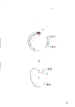
As shown in Figure 2, when image region by the red MC(R in top) and bottom Lan Se MC(B) the sign encirclement time, this range image that is recorded also has the part of a top redness and the part of bottom Lan Se.Owing to determine that at present flag color only relates to capable part, therefore for the sake of clarity, if whole image is with the work of the employed same color record of first sign MC then better.
In view of of shortcoming and the restriction of traditional apparatus for the treatment of colour pictures at the flag color transfer capability, purpose of the present invention just provides a kind of apparatus for the treatment of colour pictures, this device can make an image that is labeled avoid because of the sign density unevenness causes recording quality to reduce, and also can prevent that the image that is labeled is by with the different colours record simultaneously.
For achieving the above object, the apparatus for the treatment of colour pictures that is provided comprises: image reading device is used for that an image on the original paper is used as the image that three looks separate and reads.The colour coding generation device is used to produce indication and adorns by image reading whether each visual pixel of each look separation of reading is white, achromatic or colored; The color generation device is used for each look is separated the concentration data that image is converted to the record color that depends on image; The mark region pick-up unit is used for detecting the sign on the original image according to the color code signal by the generation of colour coding generation device, and extracts the zone that sign is enclosed; The flag color conversion equipment, expansion is by the concentration data decision of the sampling spot on the sweep trace of logo area and that pixel of a pixel is measured on main scanning direction, and the expansion concentration data that previous sweep trace is measured on auxiliary scanning direction, thus, the concentration data at sampling spot place and flag color are regarded as wearing the concentration data and the flag color of whole logo area.
By above coordination, sampled concentration data and the flag color of a fixed point on certain sweep trace of logo area to measure this point.Concentration data and the flag color of measuring is diffused into whole logo area, as a token of data several times and flag color thereupon.
So, indicate that the image in the logo area of surrounding has the concentration corresponding with concentration data, and also the color with the sign at sampling spot place is identical to write down color.
For the concentration data that will measure at the sweep trace sampling spot of logo area and sampling spot with flag color, homogenizing is to the concentration data and the flag color of whole logo area, the concentration data of measuring pixel expansion of pixel on main scanning line, expand along auxiliary direction of scanning in the data of measuring on the previous sweep trace (as the data of on initial sweep trace, measuring), as shown in Figure 3.
When certain zone was had the sign mark of two kinds of colors, as shown in Figure 2, the image color in closed region or the ring-shaped area was converted into the color of originally measuring.
Even if as shown in Figure 4, when the zone of a special shape was had the sign mark of two kinds of colors, the color of the picture information in the marked region was also changed as shown in figure.
Above-mentioned purpose of the present invention and other purpose, characteristics and advantage will become more clear by the following explanation that combines with accompanying drawing, and accompanying drawing has shown most preferred embodiment of the present invention.
Fig. 1 is the synoptic diagram of measuring the flag color concentration style to Fig. 4;
Fig. 5 is the block scheme according to apparatus for the treatment of colour pictures of the present invention;
Fig. 6 is the positive view that shows the general structure of the color dub machine that is combined with apparatus for the treatment of colour pictures;
Fig. 7 A and Fig. 7 B are the coordinate diagram that shows the character of various concentration;
Fig. 8 is the colour coding table;
Fig. 9,10,11 and 14 colour correction (maskimg) coefficient table;
Figure 12 is a kind of L
*a
*b
*Coordinate system;
Figure 13 shows L
*a
*b
*Graph of a relation between coordinate system and the cut section;
Figure 15 is the block scheme of color recycled treatment circuit;
Figure 16 A, 16B and 17A, 17B, 17C are color recycled treatment circuit principle of work synoptic diagram.
Figure 18 is the block scheme that linear color is proofreaied and correct (masking) circuit;
Figure 19 A, 19B are linear color correcting circuit fundamental diagrams;
Figure 20 A and 20B are flag color transfer process figure;
Figure 21 is a flag color change-over circuit block scheme;
Figure 22 and 23 is flag color change-over circuit fundamental diagrams;
Figure 24 is the block scheme of area detector;
Figure 25 is the block scheme that the main scanning direction sign is interrupted corrector;
Figure 26 is the logo area synoptic diagram;
Figure 27 A, 27B and 28A are the logo area signal graphs to 28G;
Figure 29 is a flag color concentration detection apparatus block scheme;
Figure 30 is that flag color concentration detects synoptic diagram to Figure 34.
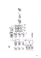
As shown in Figure 5, a kind of according to apparatus for the treatment of colour pictures of the present invention, comprise a R-CCD(charge-coupled image sensor) 1 be used for former red image conversion is become picture intelligence, a G-CCD, the former image conversion that is used for green is a picture intelligence, and a B-CCD3, the former image conversion that is used for blue look is a picture intelligence.
The picture information (optical image) that is included on the original paper that will write down or duplicate at first is separated into the look separation image of representing color information R, G, B, and these looks are separated the poly-R-CCD1 that arrives separately of image, G-CCD2, and on the B-CCD3.
Apparatus for the treatment of colour pictures has an A/D converter 4 and is used for converting the red picture intelligence that R-CCD1 reads to 8 bit digital signal, an A/D converter 5, be used for converting the green video signal that G-CCD2 reads to 8 Bit datas, a kind of A/D converter 6 becomes 8 one-bit data signal with the blue color picture conversion of signals that B-CCD3 reads.
After picture intelligence was converted to corresponding 8 one-bit data signal by A/ D converter 4,5,6, the shading value (shadiny) that look separates image also obtained proofreading and correct according to the pictorial data on the white plate of a reference.
Red, green, the blue chromatic number word picture intelligence that comes from A/ D converter 4,5,6 is converted to 6 Bit datas separately by a reference concentration converter 7.Reference concentration converter 7 offers a colour coding generator that produces colour coding with 6 digital bit picture intelligences.Reference concentration converter 7 is only used for producing colour coding.
Colour coding is two bit numbers, and it is white being used to indicate each pixel, black or colour.For example, the colour coding of white pixel is " 00 ", and the colour coding of black and white pixel is " 11 ", and the colour coding of color pixel is " 10 ".
R, G, the B digital image signal of A/ D converter 4,5,6 outputs also offers output valve can be by the variable concentrations converter 8 of operator's adjustment.Variable concentrations converter 8 will be described in detail below.
Apparatus for the treatment of colour pictures is used for colour balance by comprising a colour balance key 102; Concentration key 104 is used to adjust color density; Status key 106 is used to select picture state or character state (or other state).The input signal of these keys 102,104,106 is sent to the CPU108 as controller.
CPU108 produces reference address according to input signal, and delivers to variable concentrations converter 8, and visit is stored in the data of variable concentrations converter 8 and produces R, G, B, 6 bit concentration signals according to reference address.
According to R, G, B, 6 bit concentration signals that variable concentrations converter 8 produces, color recycled treatment circuit 10 is regenerated colored from red R, green G and blue B, as yellow Y, pinkish red M, deep blue C and black K, and produces Y, M, C, K6 bit concentration signal.
Y, M, C, K6 bit concentration signal offer near the colour ghosts of black letters that colour ghosts corrector 29 is used to remove reproduction.Colour ghosts corrector 29 is used in one 1 * 7 limiter (window) and detects a pixel and whether produce ghost image, and the colour coding that will detect the pixel of color ghost image converts the correction colour coding to.This colour ghosts trimming process is carried out simultaneously in main sweep and auxiliary scanning direction.
For the detailed content of colour ghosts corrector 29, postpone publication, publication No. № .1(1989 referring to Japan)-195775.
Flag color change-over circuit 30 detects mark region, indicates the zone that surrounds as the quilt on the original paper, and the color conversion of logo area is become the color of sign.Flag color change-over circuit 30 produces one 6 bit flag color density signal 0 and a logo area signal Q.
The flag color concentration signal of flag color change-over circuit 30 output carries out various forms of image processings such as filtering, amplification, halftone process by presentation manager 80.Be converted to multi-valued signal by pulse-length modulation (PWM) multi-valued signal generator 82 according to pulse-length modulation from 6 bit flag colour saturation signals of presentation manager.Printing machine part 84 produces color image by superpose in succession Y, M, the last toner image of C, K on light sensation drum (OPC).
Below will more describe in detail the ingredient of apparatus for the treatment of colour pictures.
The general structure of the color dub machine that is combined with apparatus for the treatment of colour pictures at first, shown in Figure 5 and operating process will contrast Fig. 6 and be described.
Suppose that the color dub machine utilizes a kind of " dry type " image development method, make two parts noncontacts, and negative image development.The color dub machine does not comprise the image conversion drum that is used to produce image, but has a light sensation drum to be used to superpose look separation image to produce color image.
Herein, the size of the color dub machine in the illustrated example is less relatively, and works in the following manner, and when the light sensation drum produced four rotations, four look separation graph produced in succession and are transformed into immediately on the recording chart (as blank sheet of paper) on the light sensation drum.
The initiating key (not shown) of pressing on the color dub machine control panel that duplicates is given original paper reader A power supply.The original paper that duplicates 101 that is loaded with color image is placed on the original paper back up pad 128, and by the optical system optical scanning.
Optical system comprises vehicle frame 132, is loaded with light source 129 and catoptron 131 as halogen lamp, also comprises removable reflection mirror component 134, it have two catoptrons 133,133 that become V-structures '.
Vehicle frame 132 and removable reflection mirror component 134 towards giving fixed direction, drive (not shown) to give fixed speed by step motor on slide rail 136.
Light source 129 irradiation original papers 101 are from the reflected light that includes original paper 101 visual optical information of original paper 101 mirror 131,133,133 ' the reflex to optical information converting member 137 that is reflected.
With reference to being connected to original paper back up pad 128 lower surface left ends (seeing shown in Figure 6) by white plate 138 when original paper 101 is by optical scanning, reference white colour table 138 is also produced a reference white color signal by optical scanning, and it can obtain the picture intelligence contrast proofreading and correct.
Optical information converting member 137 comprises lens 139, the catoptron 102,103 of prism 140 and a pair of color separation, comprise that also R-CCD1 is used to produce red look separation graph picture signals, G-CCD2 is used to produce green look separation graph picture signals, and B-CCD3 is used to produce Lan Sese separation graph picture signals.
Assembled by lens 139 from the light signal that optical system is sent, and be divided into the optical information and the yellow optical information of blue look by the dichronic mirror in the prism 140 102.Yellow optical information is resolved into red and green optical information by the dichronic mirror in the prism 140 103 then.Utilize this mode, the coloured light that the colour optics image from original paper that is produced by optical system is broken down into is learned information, i.e. R, G, B, optical information.
So look dissociated optical image is focused at corresponding R-CCD1, G-CCD2 and the photosurface of B-CCB3, produces corresponding visual electric signal.Then, the signal processing system that comprises apparatus for the treatment of colour pictures shown in Figure 5 is handled these picture intelligences.Picture intelligence after the processing then is sent to the register system B corresponding to printing machine part 84 shown in Figure 5.Register system B comprises that a light deflector 141 can be an inspection stream mirror (galvanomerric mirror), polygonal rotating mirror or quartzy light deflector.
Scanned to imaging body or light sensation drum 142 by light deflector 1141 deflections by the laser beam cycle of being transferred to from the picture intelligence of signal processing system.
More particularly, when laser beam begins by light deflector 141 deflections, detected by laser beam index sensor (not shown), and produce a signal, begin laser beam to be modulated with first colour signal and yellow.Modulated laser beam is to 142 scannings of light sensation drum, and the light sensation drum is charged by charger 152 when rotated equably.
Light sensation drum 142 is axially carried out the scanning of principal direction and by rotating continuously, carries out the auxiliary scanning direction perpendicular to main scanning direction along it by modulated laser beam.After the scanning of light sensation drum 142 through principal direction and auxiliary direction, produced electrostatic latent image thereon corresponding to the image of first kind of color.
Then, the electrostatic latent image on the light sensation drum 142 changes the yellow color picture of going up into by the visual production part 143 that includes yellow material.In the middle of work, provide one to give fixed bias voltage to image generation apparatus 143 by high voltage power supply device.
Image production part 143 can add colorant, and is when needs, not shown according to system control CPU() command signal, supply to it by colorant supply part (not shown).
Color picture carries out continuously having on the light sensation drum 142 that is in the cleaning foil 147a that is lifted away from shape on the yellow.Then, according to second kind of color image as magenta, on the light sensation drum with yellow on color picture be electrostatic latent image of overlaying relation generation.Then, the visual production part 144 that includes pinkish red colorant in the new electrostatic latent image that produces produces color picture on the magentas.Equally, provide to visual production part 144 by high-voltage suppling power and give fixed bias voltage.
Similarly, according to the third chrominance signal, as the avy blue signal, light sensation drum 142 produce electrostatic latent images be superimposed upon present generation on the color picture, and produce color picture on the avy blues by the visual production part 145 that includes the avy blue colorant.At last, according to the 4th kind of chromaticity diagram picture signals, as black signal, produce on the light sensation drum 142 be superimposed upon present generation on electrostatic latent image on the color picture, and the visual production part 146 that contains black pigment by look subsequently produces color picture on the black and white.
So, produced on the light sensation drum 142 multicoloured on color picture.
Color picture comprises four kinds of colors on the multicolour in the illustrated embodiment, also can produce on the light sensation drum 142 comprise two kinds of colors become single color on color picture.
In illustrated embodiment, be converted into the dyeing image according to two parts noncontact jump imaging methods (two-component Non-contact JunyPing deuelopment pnocess) electrostatic latent image, wherein, under the effect of interchange AC that provides by high-voltage power supply and direct current DC bias voltage, make colorant from image generation apparatus 143,144,145,146, be attached to and make the electrostatic latent image imaging on the light sensation drum 142.
In the time of needs, image generation apparatus 144,145,146 can add colorant according to the command signal that system control CPU.
Paper supply unit 148 provides recording chart P, and rolls axle 150 by paper supply roll 149 and timing and deliver to light sensation drum 142 with the rotation of light sensation drum 142 by the regular hour relation.Polychromatic dyeing image on the light sensation drum 142 is transferred on the recording chart P by the transfer electron 151 that is added with high pressure, then, by the separate mesh electrode 152 that is added with high pressure by high-voltage power supply recording chart P is separated with light sensation drum 142.
Then, the recording chart P that separates from light sensation drum 142 delivers to fixation unit 152 the multicolour color picture is fixed on the recording chart P.
The polychromatic dyeing image is transferred to from light sensation drum 142 after the recording chart, by 147 pairs of light sensation drums of cleaning unit, 142 cleanings, and waits for that next round produces the process of image.
In cleaning unit 147, metal roll 147b is added with and gives fixed high pressure and keep contacting with light sensation drum 142, so that make colorant scrape and be easy to collection by cleaning foil 147a from light sensation drum 142.When carrying out from light sensation drum 142 removal colorant processes, cleaning foil 147a keeps 142 contacts of light sensation drum.After colorant was removed, cleaning foil 142a was lifted away from light sensation drum 142.Cleaning unit 147 also has an auxiliary roller 147C, after lifting at cleaning foil 147a, removes any remaining colorant on the light sensation drum 142.The auxiliary roller 147C rotation direction reversed bulging with respect to light sensation rotated and is pressed on the light sensation drum 142, to remove any remaining colorant on it.
As shown in Figure 5, adjustable concentration converter 8 comprises storer ROM8R, 8G, 8B, stores separately corresponding to the concentration data from R, the G of A/ D converter 4,5,6, B, digital image signal.The concentration data of each ROM8R, 8G, 8B storage is shown in Fig. 7 A and 7B.
Fig. 7 A shows is the concentration data of the picture mode selected by status key 106, the concentration data of the character pattern of being selected by status key 106 that Fig. 7 B shows.
No matter be picture mode or character pattern, can select by status key 106, select concentration data corresponding among ROM8R, 8G, the 8B, according to the colour balance of colour balance key 102 indications, and the concentration of concentration key 104 indications, can obtain suitable concentration curve and concentration data.
As mentioned above, colour coding generator 9 produces 2 bit colour codings, and color recycled treatment circuit 10 produces Y, M, C, K6 bit concentration signal.According to R, the G of reference concentration converter 7 outputs, the data of B digital image signal, whether colour coding generator 9 produces pixel of expression is white, black or colored colour coding.Fig. 8 has shown this colour coding, and " 00 " represents white, and " 11 " represent black " 10 " expression colored.The process of the colour coding that produces will be described below.
Produce white colour coding:
The concentration of R, G, B will be converted into the value of XYZ coordinate system according to following equation:

Then, the value in the XYZ coordinate turns to single color space L according to following equation
*a
*b
*(uniform perceptuar color space L
*a
*b
*) value in the coordinate:
L
*=116(Y/YO)
1/3-16 …(2)
YO=100 wherein,
XO=98.07,
ZO=118.28。
Waiting chromaticity coordinates L
*a
*b
*Middle area L
*Pixel in 〉=90 is regarded as the pixel in the white portion, and these pixels are invested white colour coding.
Produce achromatism (black) colour coding:
According under establish an equation and can determine parameter QK by R, G, B concentration:
The zone of QK≤15 is regarded as black region, and the pixel in these zones is invested the black colour coding.
Produce coloured colour coding:
Zone beyond white area and the black region is regarded as coloured district, and the pixel in this zone is endowed coloured colour coding.
Color recycled treatment circuit 10 converts 6 bit R, G, B concentration signal to Y, M, CK6 bit concentration signal, owing to be used to scan the optical system of original paper or the spectrum sensitivity of scanner, the spectral reflectivity that reaches colorant has nothing in common with each other, and R, G, the B concentration determined on the scanning basis are converted to C, M, Y colorant concentration according to linear color bearing calibration (square journey 1).
According to the present invention, the colour correction coefficient calculations is as follows:
Utilize seven kinds of sample of color R, G, B, C, M, Y, K color space to be divided into six districts, as shown in figure 13, Figure 13 is L
*a
*b
*Be unified vision color space coordinate system.
Then, utilize the color (three kinds) on cut zone summit, the used colour correction coefficient aij in this district is calculated according to above equation.For example, because zone 1 comprises color R, KM, colour correction coefficient aij(I) just use these color calculation, provide below for example.
R, the G that produces with scanner, the brightness of B picture intelligence according under establish an equation and convert corresponding concentration to:
Dr=-(64/1.5)log10{(R+0.5)/256}?…(6)
Dg=-(64/1.5)log10{(G+0.5)/256} …(7)
Db=-(64/1.5)log10{(B+0.5)/256} …(8)。
For C, M, Y picture intelligence, its brightness also is converted into corresponding concentration according to monochromatic concentration and colorant sedimentation curve (not shown).
Fig. 9 has shown the measured quantity (M/A) of the CMY colorant of R, G, B horizontal scan or brightness and the deposition used when utilizing seven kinds of color R, G, B, C, M, Y, K, calculating colour correction coefficient.
In order to express the color in the left hurdle, illustrated luminance level is produced by scanner scans R, G, B color, and illustrated colorant quantity (M/A) is to be to form the amount that the CMY color deposits by printer unit.
Figure 10 illustrates the relation between the deposition M/A of colorant and concentration Dr, Dg, the Db.
According to the form among Fig. 9 and Figure 10, and equation (6) is to equation (8) colour correction coefficient aij(I) to the ajj(VI) calculated, make the equalization of concentration of the concentration of RiG, B and C, M, Y.Figure 11 has shown that by way of example the I district that calculates arrives the colour correction coefficient in VI district.
According to above process, after conversion, at least five kinds of color R, G, B, Y, M, C, K keep identical fully.Any contingent transformed error corresponding to the color in the cut section is also not obvious, because the area of cut section is very little.
After the colour correction coefficient utilized cut section to calculate, any transformed error all was reduced to minimum as shown in figure 12, has improved color reducibility.
Use cut section to calculate the possible interruption that the colour correction coefficient causes the color of the conversion of boundary between the zone, this possible color is interrupted and will analyzes below.
Border between regional I, the II will be described below.Then, following description also is suitable for border between other zone.
At first, determine the equation of boundary surface, and the linear mask matrix of substitution zone I II.If these matrixes equate that then two all interior numerical value of boundary surface equate that all the conversioning colour that proves the crossing the boundary face is continuous.
As Figure 13 and shown in Figure 14, regional I, the border π between the II passes three points, white (W), M, K.The vector r that sends from initial point points to the some P on the π of interface, can be expressed as:
r=αB+βM ……(9a)
Wherein α, β are any real number.The spoke degree (concentration) of vector is:
(Dr,Dg,Db)=α(a,a,a)+β(b、c,d) ……(9b)
Substitute a, b, c, d with the value among Fig. 9 to 11, draw down and establish an equation:
Dr=1.028α+0.253β
Dg=1.028α+0.709β …(10).
Db=1.028α+0.551β
Color correction matrix with these equation substitution zone I draws following equation:

Color correction matrix with above equation substitution zone II draws
As a result, utilize colour correction coefficient aij(I) for regional I and mask coefficient aij(II) value on the boundary surface that calculates for regional II is identical.Therefore, being interrupted appears in the conversioning colour of crossing the boundary face end.
Figure 15 illustrates in greater detail color recycled treatment circuit.
R, G, B signal (brightness) are handled in the above described manner and are converted to C, M, Y-signal by linear color correcting circuit 20.Then, C, M, Y-signal are sent to owes look remover (UCR) 12, and it is with black pigment concentration K replace black colour content (owing look).
At first, C, the netrual colour concentration C of equal value of M, Y-signal ', M ', Y ' press establish an equation definite:
C′=αC
M′=βM
Y′=γY …(13).
These equations show, if avy blue concentration is C, the concentration of the black that magenta M by adding appropriate amount at avy blue and yellow Y produce then be C ', also are like this for the concentration of magenta and yellow.
Above-mentioned factor alpha, β, γ select above-mentioned six colour correction coefficients to determine according to following equation:
Wherein, a11-33 be the cut section I to the colour correction coefficient isochrome concentration C of VI ', the reckling of M ', Y ' represents the concentration of black content (owing look), and replaces as follows with black pigment concentration:
K=min(C′,M′、Y′)
Wherein, min() be the function that minimum value in the bracket is determined in expression.
In order from the CMY signal, to remove black content (owing look), black content concentration can from etc. remove the colour saturation, its difference can be removed by above-mentioned coefficient, is expressed as follows:
C=(C′-K)/α
M=(M′-K)/β
Y=(Y′-K)/γ …(16).
Utilize this mode, owe look removal process and carried out, and produce C, M, YK signal.
Figure 16 A and Figure 16 B have shown that owing look removes process.In this example, avy blue C with minimum netrual colour concentration of equal value (shown in Figure 16 A shade) is used as reference, the avy blue concentration of control reference, netrual colour concentration C ' M ' Y ' of equal value is removed, then, as shown in figure 16, minimum avy blue concentration is replaced by black concentration K, therefore, obtain hundred-percent removal.
After owing look and being removed, its concentration converts colorant deposition M/A to by colorant deposition converter 14, then, is proofreaied and correct by 16 pairs of colorant depositions of colorant deposition corrector M/A.
More particularly, as Figure 17 A, 17B, and 17C shown in, when image printing element 84 in, utilize superpose colorant Y, M, when being recorded with certain recording impulse width such as Wa, desirable is the deposition identical (Figure 17 A) of colorant Y, M.But in fact, the deposition of colorant M when monochrome is regenerated be its answer deposition 78%, shown in Figure 17 B.
For avoiding above shortcoming, except being used to deposit the recording impulse width W a of colorant Y, the recording impulse width of deposition colorant M increases Wb, shown in Figure 17 C, the deposition that makes colorant during with monochromatic regeneration right deposition identical.Therefore, the colorant deposition deviation of deposition obtains proofreading and correct on light sensation drum 142.
The CMYK signal that obtains proofreading and correct according to the colorant deposition is sent to selector switch 18 then, and this device is once selected a signal in the CMYK signal.
As mentioned above, the image of a color of printing element 84 single passes, and on light sensation drum 142, produce color image by stacked system.
2 bit scan sign indicating numbers are added on selector switch 18, and provide C, M, Y, K signal with synchronous mode of scan period to printing element 84 selectively by selector switch 18.
Figure 18 has shown linear color correcting circuit 20 by way of example.
If the color space is divided into six pressures as shown in figure 13, then linear color correcting circuit 20 has six linear color correcting units 21 to 26, is used for storing respectively six colour correction coefficient aij(I) to the aij(VI).C, M, YK signal from linear color correction portion 21 to 26 are selected by MUX 27.R, G, the B signal of input is sent to area part 28 and determines R, the G of input, the zone under the B signal, and output signal delivered to multichannel select part 27 to select to come from the signal of linear color correction portion 21 to 26.Linear color correcting circuit 20 can be single ROM spread pattern.
Region decision part 28 is constructed as follows:
Figure 19 A has shown concentration D
r, D
g, D
bA right angle flute card coordinate system.If the concentration signal of scanner output is expressed as D
r, D
g, D
b, then their coordinate can be expressed as DRGB(OX at this coordinate system).
Interface π comprises an X and is in and the vertical position of vector OY of representing netrual colour concentration.Have component r, g, b, then as vector OY, component r, g, b, equate, be expressed as follows:
r=g=b=k
Wherein k is a real number.Therefore, vector OY can be represented as:

Be included in the π of interface as fruit dot Y, following conditions is met:
…(19).
Establish an equation under promptly satisfying:

If the component of substitution vector, then:
OY·(OX-OY)=O
(k,k,k)·{(Dr,Dg,Db)-(k,k,)}=O
(k,k,k)·(Dr-k,Dg-k,Db-k)=O
k{Dr+Dg+Db-3k}=O …(21).
Because k ≠ O,
k=(Dr+Dg+Db)/3 …(22).
Point on the π of interface satisfies formula (22) requirement, and the corresponding point on interface π and the coordinate axis can be expressed as:
R(3k,O,O);G(O,3k,O),
B(O,O,3k) …(23).
Figure 19 B has shown the interface π that is seen from vector OY extended line position.
Point R, G, B, X, Y are on the π of interface, be regarded as initial point among Figure 19 B as fruit dot Y, and the angle of vector Y R are 0
0, then the angle Q of vector Y λ is drawn by following formula:
ⅰ) as Dg>Db, θ=COB
-1

ⅱ) as Dg<Db, θ=π-CO
-1

Determine corresponding to C by giving earlier
1Angle<the RYTM of M, YRGB dyeing image,<RYTB ..., and according to six regional I of angular divisions of determining to VI, after angle θ was definite by R, G, the B signal of input, regional I can be determined to VI
The effect of flag color change-over circuit 30 is the colors that the color conversion of the blackaandawhite characterumay of being surrounded by colored sign on the original paper become color sign.
Figure 20 has shown the flag color transfer process.Figure 20 A has shown the original paper before the flag color conversion, and Figure 20 B has shown the output image that writes down after the flag color transfer process is carried out.The black character that is surrounded by the sign of colour at original paper among Figure 20 A changes the character with the same color of flag color into.Color sign is not limited to certain specific color.
The formation of flag color change-over circuit 30 as shown in figure 21.
Flag color change-over circuit 30 comprises an area detector 40, is used to examine will color sign MC, and the zone that eliminating color sign MC is enclosed is to produce a logo area signal Q.Simultaneously, the sampling of the concentration data of the color of 50 pairs of color signs of flag color sampling part (can C, MY or K) is got school signal H with what produce concentration data.
Flag color change-over circuit 30 comprises that also flag color concentration judgment part 60 is used to judge whether sampled signal H adopts the concentration data of making sign MC.Added signal has logo area signal Q to flag color concentration judgment part, and sampled signal H and supervisory signal E(below will be described)
Sign sampling monitor portion 52 monitors colored colour coding, to judge whether the sampling of sign is carried out, and is produced the supervisory signal E that representative monitors the result.
The effect that sign is removed circuit 72 is to prevent to indicate that MC also goes on record.The signal that is added on this circuit has color code signal, concentration data D, logo area signal Q and scan code.
Sign is removed circuit 72 and is used the concentration data of the input of black K to pass through when the image of black K is write down by printing 84, and when Y, M, C, K color picture are write down by printing 84, the black K concentration data of logo area is passed through.Figure 22 has shown the truth table of scan code.
Flag color change-over circuit 30 also comprises a black transition device 74, is used to increase a concentration data of the input of pin logo area, and the black concentration data of the input in the zone beyond the logo area is passed through.
The marker color density signal V(that is added on black transition device 74 will give description after a while), concentration data D, colour coding, logo area signal Q, and 2 bit scan sign indicating numbers, black transition device 74 will be converted to the target color by the black concentration data D of sign MC area surrounded.
As shown in figure 23, the concentration data by 74 outputs of black transition device is the concentration data D and the coefficient V/Do of input long-pending (DO is a constant).
The ingredient of flag color change-over circuit 30 will elaborate following.
Figure 24 has shown area detector 40 by way of example.Area detector 40 interrupts corrector 40A and mark region processor 40B by sign.
Sign interrupts corrector 40A to be proofreaied and correct sign MC litura and interruption with main sweep and auxiliary scanning direction simultaneously.Interrupt proofreading and correct among the interruption corrector 40A at sign, be converted to marking signal MS by marking singal translator 41.
When colour coding indication and colored colour coding, marking singal translator 41 produces marking signal MS.The relation of colour coding and marking signal MS is seen shown in Figure 8.Marking signal MS is sent to the main scanning direction sign and is interrupted corrector 42.
Figure 25 has represented that at length the main scanning direction sign interrupts corrector 42.The main scanning direction sign interrupts corrector 42 and comprises that single pixel delay element 421-427(of a plurality of series connection is 7 in the embodiment shown).The output signal separately of delay element 421-427 is added to characteristic processing device 428.Then the characteristic processing device 428 continuous feature of sign that will be latched in the latch 429 is changed to " 1 " when the output signal of delay element 421-427 all becomes " 1 ".
With the continuous feature supply characteristic of the sign processor 428 and the output identification signature computation unit 430 that are latched in the latch 429, computing unit 430 also obtains an output signal Mi from first delay element 421.Output identification signature computation unit 430 is the forms with a kind of logical "or" circuit, produces a sign output signal MS for " 1 " when indicating that continuous feature or output signal Mi are " 1 ".
Shown in circuit arrangement main scanning direction sign interrupt corrector 42 and can compensate at the sign of main sweep branch and interrupt at least 7 pixels of correspondence.
After the sign of main scanning direction interrupts being corrected, any sign on auxiliary scanning direction interrupts, all can adopt above-mentioned main scanning direction sign to interrupt the same manner of corrector 42, interrupt corrector 44 by next auxiliary scanning direction sign and compensate.In an illustrated embodiment, auxiliary scanning direction sign interruption corrector 44 can compensate the sign interruption corresponding at least 7 sweep traces effectively.
Mark region processor 40B produces the mark region signal Q corresponding to marking signal MC enclosing region.The operation of mark region processor 40B is described below with reference to Figure 26,27A and 27B.
When the sweep trace shown in Figure 26 scans logo area, produced the marking signal MSs as shown in Figure 27 A.Suppose when not shown in Figure 26 along previous sweep trace S-1() when scanning this logo area, produced the marking signal QS-1 shown in Figure 27 A.
With marking signal QS-1 and marking signal MSs addition, produced signal QS-1, MSs.The edge that produces then from the positive rising edge of signal QS-1MSs to its negative edge detects pulse Rs, then to marking signal MSs and edge detect pulse Rs carry out " or " handle, produce logical "or" signal QS, it is used as the mark region signal Q of this sweep trace S.
Equally, when when the sweep trace t shown in Figure 26 scans this logo area, produced the marking signal MSt as shown in Figure 27 B.Suppose when not shown in previous sweep trace t-1(Figure 26) when this logo area is scanned, produced the marking signal Qt-1 shown in Figure 27 B.
With marking signal Qt-1 and marking signal MSt addition, produced signal Qt-1MSt.The edge that has produced then from the rising edge of signal Qt-1MSt to its negative edge detects pulse Rt.Again the back to marking signal MSt and edge detect pulse Rt carry out " or " handle, produced a logical "or" signal Qt, it is used as the mark region signal Q of this sweep trace t.
In the above described manner this logo area is detected.Then, need sample to the color data of sign.
In this embodiment, in order to obtain stable color data, for the level of density of each its sign of sampling of 4 continuous pixels, its first pixel is sampled signal (Figure 28 C) the H(density data that 4 pixels (Figure 28 A and 28B) and the mean value that will be sampled the level of density of pixel are used as C, M in marking signal MS, Y, K colour apart from the edge of this sign).
At the sampling of the sign shown in Figure 21 monitor unit 52, make that when marking signal MS does not comprise achromatic colour code the sampling process in sign color sampling unit 50 can be carried out effectively.
Sign sampling monitor unit 52 produces a supervisory signal E, and it makes to have only when an achromatic colour code is arranged outside the marking signal MS sampling process could carry out (Figure 28 D-Figure 28 G) effectively.
Being constructed as follows of sign colour density determining unit ratio:
As shown in figure 29, sign colour density determining unit 60 comprises: sign colour density determine lu 6.2, one be used for during a pixel in the memory and a pair of latch 66,68 of this write data.In order to be more readily understood the write and read operation of memory 64, in Figure 29, this memory 64 is shown two memories, but is in fact indicating the memory that has only of colour density determining unit 60 employings.
Be the counting of 2 figure place devices on the U in Figure 29, V is the colored density data of sign, and n is the number that expression sweep trace j represents pixel, and F is the feature the indication whether colored density data of sign is determined.
To indicating that colored definite lu 6.2 supply has:
(1) mark region signal Q;
(2) sampled signal H;
(3) supervisory signal E;
(4) feature F;
(5) the counting U that reads from memory 64; With
(6) the density signal V that is used for this and preceding sweep trace that reads from memory 64.Respond these signal supplied, sign is colored determines that lu 6.2 produces:
(7) the counting U of this sweep trace writes memory 64 with it; With
(8) the density signal V of this sweep trace writes memory 64 with it.
The condition of the density of determining sign MC will be described below.In the following description, suppose think the data of sign MC from the data of the three scan line of logo area initiating terminal.
(I) works as Q=O:
At this moment,, do not need color transformation because this logo area is not scanned, so data are:
Uj(n)=O and
Vj(n)=and O, it is write, and feature is Fj=O.
(II) works as Q=1, Uj+4(n-1)<3, and Fj=O:
When the sampling along the first sweep trace scanning flag MC and pixel is with the plain beginning of four-quadrant when effective, from which pixel supervisory signal E=1.
Therefore, Uj(n)=Uj+4(n-1)+1 and
Vj(n)=H
They are write, and it is characterized in that Fj=0.
So, when counter output increases by 1 with the data Uj+4(n-1 that is produced)+1 storage is as the counter output Uj(n of this sweep trace n).Because store density data first, also with the density data Vj(n of sampled signal H) storage itself.
Therefore, store density data (on average) as shown in Figure 3 from the 9th pixel generation.
For pixel afterwards, also will store the density data Vj(n of sampled signal H) itself.
Because adopt density data, also do not determine (Fj=O) so indicate the density data of MC this moment along three scan line.
Because the Q=O outside mark region, will adopt outside the mark region above-mentioned under condition (I) formula, and its density data keeps uncertain.
In Fig. 3, circle is represented the pixel on the sweep trace, and the triangle on the pixel of sweep trace is represented the density data of those pixels.The 1st pixel with three cornet marks on each sweep trace is the 9th pixel.To be used as density data with the PEL (picture element) density of those round spot signs.
(III) works as Q=1, Uj+4(n-1)<3, E=1, Fj=1:
For the 10th on same n sweep trace and pixel thereafter, the density data on being stored on each pixel.Therefore,
Uj(n)=Uj+4(n-1)+1 and
Vj(n)=H
They are write, and it is characterized by
Fj=1。
Therefore, as shown in Figure 3, be stored in the density data (on average) on each pixel.This operation is proceeded to its scanning position to be proceeded to outside the mark region along same n sweep trace.
(IV) works as Q=1, Uj+4(n-1)=3, and Fj=0:
On (n+3) sweep trace, on the 4th sweep trace, be promptly the density data of the PEL (picture element) density data-storing of 4 pixels after the same pixel on the last sweep trace as this sweep trace.The density data of storage will be used as definite density data.Therefore,
Uj(n)=Uj+4(n-1) (=3) and
Vj(n)=Vj+4(n-1)
They are write, and it is characterized by
Fj=1。
In Fig. 3, the PEL (picture element) density data of 4 pixels are density datas of the 9th pixel on (n+2) sweep trace after the same pixel on the last sweep trace.
As follows with the 10th and pixel thereafter in the n scanning: because density data is determined on the 9th pixel as mentioned above, its feature becomes Fj=1, the formula below will adopting under the condition (V):
(V) works as Q=1, Fj=1:
For the 10th on same sweep trace and pixel thereafter, adopt the density data of density data Vj-1 definite on last pixel as them.Therefore have
Uj(n)=3(=Uj+4(n-1)) and
Vj(n)=Vj-1(n)
They are write, and it is characterized in that
Fj=1。
On same line, the density data that will determine on the 9th pixel scans above-the-line promotion at this.
Outside mark region, the density data of pixel is uncertain (Fj=0).The result is for the formula of next one scanning employing under condition (II).For the 9th pixel on next sweep trace, the density data (i.e. the density data of Que Dinging) that adopts 4 pixels before the same pixel on the last line is as its density data.
Because feature is Fj=1 on the 9th pixel, according to handling at the formula under the condition (V) the 10th and the density data on the pixel thereafter.On this sweep trace, will the 9th and thereafter the density data on the pixel propagate in the direction of scanning.
The propagation of concentration data makes an explanation with reference to Fig. 3.
Logo area is in (n) OK, and following row and data handling procedure begin,
(1) goes (n)
Pixel in the indication of entity triangular form begins sampling.Be expert at (n-1), Uj+4<3 and Fj=0 are so sampling value is " H ".
(2) go (n+1)
Be expert at (n) Uj(n in logo area) increase progressively and be 1 with 1.Therefore, concentration data is the sampling value at the indicated pixel place of entity triangle.
(3) go (n+2)
(n+1) Uj(n+1 in logo area is expert at) increase progressively and be 1 with 1, therefore, concentration data is the sampling value at the indicated pixel place of entity triangle.
(4) go (n+3)
Be expert at (n+2), appoint Uj(n+2 in the logo area) increase progressively and be 3 with 1.Therefore, the concentration at the pixel place of entity triangle indication is the Vj+4(n+2 that the row (n+2) in the condition (IV) is located) value.So the concentration at Fj=1 and next pixel place is the value at the pixel place of entity triangle indication, and propagate along main scanning direction.
Because the density data on the pixel is undetermined on the n sweep trace, so the sampled signal on that pixel is used as until the density data of n+2 sweep trace according to the formula under condition (III).
On (n+3) sweep trace, be the formula according under condition (II), the density data of last sweep trace is used as this pixel.So, with X
1And X
2Sign colour and density datas different in the district are transmitted on the auxiliary scanning direction of advocating peace, up to (n+3) sweep trace.
On (n+4) sweep trace below, be to determine density data, with interval X according to the formula under condition (V)
1In the colored and density data of the sign determined be defeated by interval X
2
As a result, as shown in Figure 4, use at first at interval X
2The zone that the sign colour of determining scans has only interval X
2, up to (n+3) sweep trace.
Therefore, the colored and interval X with sign
1In determined density data almost scanned all zones.
Because the density data of next sweep trace can really be come from previous sweep trace as shown in Figure 3, and transmission is on the direction of scanning, so, can then determine color region in a line ground with line of aforesaid way.
The density data of its 4 pixels in back is used as under the situation of the density data of each pixel on next sweep trace on last sweep trace, its density data is not to set up as shown in figure 31, even be like this when the density data of last sweep trace is used as first density data of next sweep trace yet.
In this case, thereafter the density data of 4 pixels on the last sweep trace is used as the density data of each pixel on next sweep trace, because this density data is transmitted as shown in figure 33, interval X
2In density data enter interval X
1, continue, till density data that will transmission is used as first density data among the interval X always.
Finally, it is shown in Figure 34 to indicate that colour and density data are defined as, and the result has eliminated at interval X
1The sign colour of regulation.This method is to determining that the sign colour is not effectively.
As mentioned above, with the density data of γ point sampling on the 3rd sweep trace (=r1) on the main and secondary direction of scanning, transmit.As a result, the density data on the 3rd sweep trace has been used as the density data of sign MC.
So the density data of sign MC is determined on the 3rd sweep trace.Even if the colour of sign MC has changed, or has reduced in the density in the somewhere that indicates MC, still can handle logo area, and not consider to indicate the colour of MC and the variation of density.
(VI) works as Q=1, Uj+4(n-1)<3, and E=O, Fj=O;
Invalid and feature F is uncertain in sampling process, until under the situation of the 3rd line, (this situation is in fact seldom) promptly, works as E=O, Fj=O, the density data storage of last sweep trace is as follows:
Uj(n)=Uj+4(n-1) and
Vj(n)=Vj+4(n-1)
And feature is
Fj=O
Above-described the present invention is used for color copy machine.Yet not with apparatus for the treatment of colour pictures of the present invention with handle the various of various colour signal images without combining.
Adopt above-mentioned the present invention, be used in the colour and the density of the definite sign of data on the special sweep trace, and they are used as the colour and the density of this mark region.
Owing to not with one group of colored record, stand the density scrambling with the image that indicates colored record in other words, so changed the quality of recording picture by the image in the sign institute area surrounded.
Even be marked with a sign with a special plotting mode, logo area can not separated by inappropriate.
Though described certain embodiment of the present invention, should know, just can carry out many variations and modification here, and can not leave the application's claim institute restricted portion.
Claims (5)
1, a kind of color image processing device comprises:
Image reading is used for an image on the original paper is read as 3 disclosed images of colour;
The colour code generation device is used to produce colour code, and each pixel that described colour code represents to be read by described image reading the color separation image is white, achromatic, or colored;
Color recycled device is used for each described color separation image transform is the density data according to its institute's recording colour;
The logo area pick-up unit, the colour code inspection that is used for producing according to described colour code generation device detects the sign on the original image; And
Sign color transformation device, be used for the density data that on the sampled point of the sweep trace of mark region, to determine, a pixel is then expanded on main scanning direction on a pixel ground, and be used for density data definite on the last sweep trace, expand on the auxiliary scanning direction, thereby the colour that indicates on density data on the sampled point and the sampled point is used as the density data and the colour of the sign of whole logo area.
2, according to the color image processing device of claim 1, wherein said color recycled device comprises that is used to duplicate a colored linear color correcting circuit.
3, according to the color image processing device of claim 2, wherein said linear color correcting circuit is made up of the ROM table.
4, according to the color image processing device of claim 1, wherein said logo area pick-up unit comprises: a sign interrupts correcting circuit, is used to proofread and correct main and auxiliary helping on the direction of scanning indicating the fuzzy of part and interrupting; A logo area treatment circuit is used to produce the logo area signal, and representative is by the zone that marking signal limited corresponding to colour code.
5, according to the color image processing device of claim 4, wherein said sign color transformation device comprises: a sign color sampling unit is used to export the sampled signal to indicating that colored density data is sampled, and described logo area signal is provided simultaneously; A sign sampling monitor unit is used for determining according to colour code whether the colored sampling of sign is effective, and produces supervisory signal; With a device of determining the sign colour density according to described mark region signal, sampled signal and supervisory signal.
Applications Claiming Priority (2)
| Application Number | Priority Date | Filing Date | Title |
|---|---|---|---|
| JP2025784A JP2731443B2 (en) | 1990-02-05 | 1990-02-05 | Color image processing equipment |
| JP25784/90 | 1990-02-05 |
Publications (1)
| Publication Number | Publication Date |
|---|---|
| CN1054843A true CN1054843A (en) | 1991-09-25 |
Family
ID=12175461
Family Applications (1)
| Application Number | Title | Priority Date | Filing Date |
|---|---|---|---|
| CN91100695.8A Pending CN1054843A (en) | 1990-02-05 | 1991-02-04 | Color image processing apparatus |
Country Status (4)
| Country | Link |
|---|---|
| US (1) | US5241609A (en) |
| EP (1) | EP0441575B1 (en) |
| JP (1) | JP2731443B2 (en) |
| CN (1) | CN1054843A (en) |
Families Citing this family (16)
| Publication number | Priority date | Publication date | Assignee | Title |
|---|---|---|---|---|
| JP2600515B2 (en) * | 1991-05-14 | 1997-04-16 | 富士ゼロックス株式会社 | Image processing method |
| JP2990306B2 (en) * | 1991-05-14 | 1999-12-13 | 富士ゼロックス株式会社 | Marker dot detection method for color image recording device |
| JP3295970B2 (en) * | 1992-07-21 | 2002-06-24 | 富士ゼロックス株式会社 | Area recognition device |
| DE69228120T2 (en) * | 1992-10-19 | 1999-08-05 | International Business Machines Corp., Armonk, N.Y. | Method and device for suppressing a color in multicolor documents |
| US5960109A (en) * | 1993-09-07 | 1999-09-28 | Xerox Corporation | Single pass marker enclosed area detection system and method for a photocopier |
| DE69424904T2 (en) * | 1993-09-14 | 2001-08-02 | Canon K.K., Tokio/Tokyo | Image processing device for processing an image marking |
| US5696539A (en) * | 1993-12-08 | 1997-12-09 | Hewlett-Packard Company | Method for matching colors of data displayed on connected computer systems |
| JPH08130631A (en) * | 1994-10-28 | 1996-05-21 | Canon Inc | Image processor and image processing method |
| JPH11298795A (en) * | 1998-04-14 | 1999-10-29 | Sony Corp | Control signal generating circuit |
| US5995655A (en) * | 1998-06-09 | 1999-11-30 | Silicon Graphics, Inc. | System and method for coding colors and storing compensation factors used in color space conversion |
| JP4586241B2 (en) * | 2000-06-14 | 2010-11-24 | コニカミノルタビジネステクノロジーズ株式会社 | Image processing device |
| JP2005088434A (en) * | 2003-09-18 | 2005-04-07 | Minolta Co Ltd | Image forming device |
| JP4612309B2 (en) * | 2004-01-07 | 2011-01-12 | セイコーエプソン株式会社 | Color conversion for color printers |
| US7570403B2 (en) * | 2005-03-16 | 2009-08-04 | Kabushiki Kaisha Toshiba | Color image processing apparatus |
| US7630544B1 (en) * | 2005-04-06 | 2009-12-08 | Seiko Epson Corporation | System and method for locating a character set in a digital image |
| JP2008052709A (en) * | 2006-07-26 | 2008-03-06 | Canon Inc | Image processing apparatus, method of controlling same, and program |
Family Cites Families (8)
| Publication number | Priority date | Publication date | Assignee | Title |
|---|---|---|---|---|
| US4538182A (en) * | 1981-05-11 | 1985-08-27 | Canon Kabushiki Kaisha | Image processing apparatus |
| EP0300046B1 (en) * | 1987-01-27 | 1996-07-10 | Konica Corporation | Halftone colour image signal processing apparatus |
| EP0305126A3 (en) * | 1987-08-24 | 1991-03-27 | Konica Corporation | Image processing apparatus |
| JPH01198870A (en) * | 1987-10-08 | 1989-08-10 | Ricoh Co Ltd | Digital color picture processor |
| JPH01309467A (en) * | 1988-01-29 | 1989-12-13 | Konica Corp | Picture processing unit |
| EP0588380B1 (en) * | 1988-06-08 | 2003-03-20 | Canon Kabushiki Kaisha | Image processing apparatus and method |
| US5130791A (en) * | 1988-07-15 | 1992-07-14 | Konica Corporation | Color image processing apparatus |
| DE69021107T2 (en) * | 1989-03-22 | 1995-12-14 | Konishiroku Photo Ind | Image processing device capable of detecting marked areas. |
-
1990
- 1990-02-05 JP JP2025784A patent/JP2731443B2/en not_active Expired - Lifetime
-
1991
- 1991-02-04 CN CN91100695.8A patent/CN1054843A/en active Pending
- 1991-02-04 EP EP91300889A patent/EP0441575B1/en not_active Expired - Lifetime
- 1991-02-05 US US07/650,856 patent/US5241609A/en not_active Expired - Fee Related
Also Published As
| Publication number | Publication date |
|---|---|
| EP0441575B1 (en) | 1996-12-18 |
| JPH03230681A (en) | 1991-10-14 |
| US5241609A (en) | 1993-08-31 |
| EP0441575A3 (en) | 1992-06-03 |
| JP2731443B2 (en) | 1998-03-25 |
| EP0441575A2 (en) | 1991-08-14 |
Similar Documents
| Publication | Publication Date | Title |
|---|---|---|
| CN1241390C (en) | Device and its method for processing combined image of contracted character, stick figure and net point | |
| CN1123205C (en) | Image-formation apparatus and image-processing apparatus | |
| CN1059063C (en) | Image forming apparatus and method | |
| CN1083995C (en) | Image processing method and apparatus thereof | |
| CN1054843A (en) | Color image processing apparatus | |
| CN1264121C (en) | Digital image sharpening system | |
| CN1262971C (en) | Image processing device | |
| CN1732682A (en) | Image processing device and image processing program | |
| CN1310521C (en) | Image siganl processor, image signal processing method, learning device, learning method, and recorded medium | |
| CN1764228A (en) | Image processing apparatus, image forming apparatus, method for processing image, | |
| CN1134727C (en) | Printer | |
| CN1753445A (en) | Image reading apparatus | |
| CN1484114A (en) | Image process apparatus | |
| CN1260947C (en) | Image processing method and device, image forming device, program and recording medium | |
| CN1645942A (en) | Image-processing apparatus, image-capturing apparatus, image-processing method and image-processing program | |
| CN1625221A (en) | Image forming device, pattern forming method and its program | |
| CN1526115A (en) | Method and a system for reducing update frequency of image processing device | |
| CN1893535A (en) | Density determination method, image forming apparatus, and image processing system | |
| CN1465041A (en) | Image display system, projector, information storage medium and image processing method | |
| CN1229969C (en) | Color conversion device and color conversion method | |
| CN101076126A (en) | Imaging apparatus and method, and imaging device | |
| CN1809117A (en) | Image processing apparatus, image forming apparatus, image reading process apparatus, image processing method, image processing program, and computer-readable storage medium | |
| CN1805499A (en) | Image processing apparatus, image forming apparatus, image reading process apparatus and image processing method | |
| CN100350790C (en) | Color converting device and method, image forming apparatus, program and recording medium | |
| CN1186919C (en) | Image processing method and device |
Legal Events
| Date | Code | Title | Description |
|---|---|---|---|
| C06 | Publication | ||
| PB01 | Publication | ||
| C01 | Deemed withdrawal of patent application (patent law 1993) | ||
| WD01 | Invention patent application deemed withdrawn after publication |