CN1052768C - Rotary thread takeup lever in sewing machine - Google Patents
Rotary thread takeup lever in sewing machine Download PDFInfo
- Publication number
- CN1052768C CN1052768C CN95121781.XA CN95121781A CN1052768C CN 1052768 C CN1052768 C CN 1052768C CN 95121781 A CN95121781 A CN 95121781A CN 1052768 C CN1052768 C CN 1052768C
- Authority
- CN
- China
- Prior art keywords
- thread
- takeup lever
- lever
- arm
- rotary
- Prior art date
- Legal status (The legal status is an assumption and is not a legal conclusion. Google has not performed a legal analysis and makes no representation as to the accuracy of the status listed.)
- Expired - Lifetime
Links
Images


Classifications
-
- D—TEXTILES; PAPER
- D05—SEWING; EMBROIDERING; TUFTING
- D05B—SEWING
- D05B49/00—Take-up devices, e.g. levers, for the needle thread
- D05B49/04—Take-up devices, e.g. levers, for the needle thread rotary
Landscapes
- Engineering & Computer Science (AREA)
- Textile Engineering (AREA)
- Sewing Machines And Sewing (AREA)
Abstract
A rotary thread take-up lever for acting on an upper thread in a sewing machine, comprising: a base portion which is continuously rotatable around a predetermined axis in one direction; and an arm extending outwardly from the base portion with respect to the axis, the arm including a front edge facing in the direction of rotation of the thread take-up lever and a rear edge facing in the direction opposite to the direction of rotation of the thread take-up lever. The front edge has a thread holding point, wherein the upper thread being lifted by the thread take-up lever is slid on the front edge. The rear edge has a thread holding point, wherein the upper thread being supplied from the thread take-up lever is slid on the rear edge. When the upper thread is supplied maximally, the upper thread is held by the thread holding points of the front and rear edges, respectively. The radius of rotation of the thread holding point on the rear edge is smaller than the radius of rotation of the thread holding point on the front edge.
Description
The present invention relates to a kind of rotary thread takeup lever of Sewing machines.
In a Sewing machines, its rotary thread takeup lever is carried out following a series of operation: the rotary thread takeup lever in the future upper thread of spinning shuttle is supplied to eedle, and the needs according to shuttle race cap loosen upper thread then, so that pin has been ladled out and made this upper thread pass rotary hook.In addition, when this line passed rotary hook, its rotary thread takeup lever pulled this upper thread immediately, and upper thread is supplied, and this upper thread is to be used for being formed a linear slit when feeding at workpiece.Simultaneously with the upper thread pull-up and tighten up.In the foregoing description, described " shuttle " comprises shuttle race cap and the rotary hook that can rotate within it.
This rotary thread takeup lever is a kind of like this thread takeup lever, and it carries out above-mentioned a series of operation, promptly by means of the continuous rotation of a thread takeup lever element (back will describe), carries out the upper thread supply and promotes operation.
A kind of common rotary thread takeup lever of traditional type has been shown in Fig. 6 (A) and 6 (B).Promptly this traditional type rotary thread takeup lever 20 comprises a rotary thread takeup rod element 24, and it comprises a matrix part 22 and an arm 23 that extends out from this matrix part 22.Specifically, this matrix part 22 is fastened on the spinner member 21, this element rotates along a direction around a trunnion axis, this trunnion axis is the single mandrel with this Sewing machines, for example be used for driving that a shank of crank axle links mutually, arm 23 stretches out from matrix part 22 with respect to this rotation.
This rotary thread takeup lever 20 C along clockwise direction rotates, when the wire-wound arm 23 of this rotary thread takeup lever (Fig. 8 and 9) forms a single coil face to face, in the rotary course of thread takeup lever element 24, this coil reaches forward slip backward along the front and rear edges 26 and 25 of arm 23, thereby makes this rotary thread takeup lever finish above-mentioned a series of operation.In the rotation process of thread takeup lever element 24, break away from arm in order to prevent coil, be provided with locking handgrip 27 and 28 at the free end of arm 23, and be provided with jut 29 and 30 in two sides of matrix part 22.
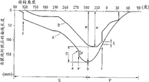
Fig. 7 has provided a curve, and it has represented the thread takeup lever curve movement A of an industrial sawtooth shape interlock sewing machine and the curve movement B of shuttle, and this Sewing machines has the above-mentioned the sort of traditional type rotary thread takeup lever 20 and the shuttle of a full rotation.In Fig. 7, its trunnion axis is represented the anglec of rotation of this Sewing machines arm axle, and vertical axis is then represented the length of the upper thread supplied with by rotary thread takeup lever.In vertical pivot, mark " 0 " is equivalent to the position of needle plate upper surface, and the curve movement A of rotary thread takeup lever is used for showing the length of the upper thread of being supplied by this rotary thread takeup lever, and the motion of shuttle curve B is then represented the length of the upper thread of being mentioned by shuttle.The length of the upper thread of so being mentioned is the scope that depends on the thread takeup lever motion.When the anglec of rotation of axle was 0 °, shank was arranged in the highest position of its range of movement (top dead-centre), and when angle is 180 °, then is positioned at its extreme lower position (bottom dead centre).
In Fig. 7, for f constantly and the time cycle of a between constantly, when slip is that when carrying out, upper thread is carried out supply to the curved portion (with dashed lines 31 is represented in Fig. 6) that relatively relaxes of that section at the trailing edge 25 of arm 23.Fig. 8 has represented the state at moment a rotary thread takeup lever 20 and upper thread 16.Before moment a, upper thread 16 is always by a bit supporting on the trailing edge 25.Make upper thread 16 have suitable tension force by couple of conductor element (not shown), described wire element lays respectively at linear slit N side and supplies line source T one side.
When rotary thread takeup lever 20 further rotates, arrive a ' time in the moment among Fig. 7, upper thread 16 is by above-mentioned locking handgrip 27 and 28 lockings, and upper thread is supplied to b (Fig. 7) constantly always, and this moment, it was supported by two branch line points 32 on the trailing edge 25 and 33.Fig. 9 has represented the state at moment b (Fig. 7) thread takeup lever 20 and upper thread 16.When thread takeup lever 20 further rotates, upper thread 19 promptly is pulled upwardly.
She Ji traditional rotary thread takeup lever 20 has following problem like this:
Length M by the sewing thread of thread takeup lever supply is greater than the maximum line length m that is handled by shuttle, thereby makes the maximum length D of scrap wire also become excessive.In addition, when shuttle was drawn in sewing thread, Sewing machines was unclamped suddenly, and like this, when the Sewing machines high-speed cruising, unsettled motion appears in sewing thread easily, thereby causes the irregularity of stitching, even might break.
Pivot by reducing rotary thread takeup lever 20 and the distance between branch line point 32 and 33 promptly reduce the radius of turn R of branch line point 32 and 33
1, can reduce the maximum length D of scrap wire.Yet in this case, the thread takeup lever curve movement A among Fig. 7 has been moved to left by integral body with respect to the curve movement B of shuttle, and the length E of scrap wire has also reduced, and this scrap wire is used for making upper thread 16 to shift out shuttle.Therefore, reduce the radius of turn R of branch line point 32
1Be unpractiaca.
Therefore, purpose of the present invention is eliminated the existing the problems referred to above of traditional type rotary thread takeup lever exactly.
Specifically, one of purpose of the present invention is the rotary thread takeup lever that a kind of use in sewing machine is provided, adopt this thread takeup lever, deviating from for upper thread under the situation that the necessary scrap wire length of shuttle remains unchanged, the maximum line length of being supplied by this rotary thread takeup lever is reduced, thereby has prevented the generation of irregular stitching and the generation of broken string.
The rotary thread takeup lever that above-mentioned purpose of the present invention is passed through to be provided realizes that this thread takeup lever can act on the upper thread of a Sewing machines, and it comprises: a matrix part, and it can rotate along a direction continuously around a predetermined axis; An arm, it stretches out from relative this axis of matrix part, and this arm comprises a leading edge and the hinder marginal part opposite with this direction facing to the thread takeup lever direction of rotation.This leading edge has one and holds the line point, and the upper thread of being supplied with by thread takeup lever slides on trailing edge.Also have one on the trailing edge and hold the line point, the upper thread of being mentioned by thread takeup lever slides on leading edge, and when the supply of upper thread was maximum, upper thread was supported by the line point that holds on the front and rear edges respectively, and the radius of turn that trailing edge holds line point is less than the radius of turn that leading edge is held line point.
Put it briefly, rotary thread takeup lever of the present invention has following function:
When rotary thread takeup lever rotated, upper thread was supplied with the form of sliding, and it is supported on any of arm trailing edge, and when further supplying with, two that then are supported in the arm front and rear edges are held on the line point, thereby realized maximum supply.After the maximum supply realizes, on being slided, draws upper thread, and this moment, it was bearing on the point of arm leading edge.
When upper thread is done maximum supply, two on the arm front and rear edges are held line point and are supporting upper thread, wherein trailing edge is after upper thread has been done maximum supply, just irrelevant with the action of last hand-pulled noodles line, the radius of turn that makes the radius of turn of holding line point of trailing edge hold line point less than leading edge, like this, when the length (E among Fig. 7) that can satisfy the scrap wire that upper thread deviates from from shuttle when remaining unchanged, then be reduced by the maximum length (M among Fig. 7) of the line of thread takeup lever supply.
Fig. 1 (A) is a width of cloth plane, and it has shown a kind of rotary thread takeup lever of the present invention for use in sewing machine, and Fig. 1 (B) is the profile of doing along b-b line among Fig. 1 (A);
Fig. 2 is a graphic representation, and it has represented to have a rotary thread takeup lever curve movement A and a motion of shuttle curve B of the industrial sawtooth shape interlock sewing machine of a rotary thread takeup lever shown in Fig. 1 (A) and 1 (B) and a full rotating shuttle;
Fig. 3 is a schematic diagram, and it has represented a moment in Fig. 2, the state of rotary thread takeup lever and upper thread;
Fig. 4 is a schematic diagram, and it has represented the b moment in Fig. 2, the state of rotary thread takeup lever and upper thread;
Fig. 5 is a schematic diagram, and it has represented the c moment in Fig. 2, the state of rotary thread takeup lever and upper thread;
Fig. 6 (A) is a plane, and it has represented a kind of traditional type rotary thread takeup lever, and Fig. 6 (B) then is the cutaway view of being done along b-b line among Fig. 6 (A);
Fig. 7 is a graphic representation, and it has shown a rotary thread takeup lever curve movement of the industrial sawtooth shape interlock sewing machine with the traditional type rotary thread takeup lever shown in Fig. 6 (A) and 6 (B) and a full rotating shuttle and the curve movement of a shuttle;
Fig. 8 is a schematic diagram, and it has represented a moment in Fig. 7, the state of rotary thread takeup lever and upper thread; And
Fig. 9 is a schematic diagram, and it has represented the b moment in Fig. 7, the state of rotary thread takeup lever and upper thread.
Figure 10 (A) and Figure 10 (B) expression an alternative embodiment of the invention.
Below in conjunction with accompanying drawing a kind of Sewing machines rotary thread takeup lever of the present invention is described.
Roughly shown in Fig. 1 (A), in Fig. 1 (A), rotary thread takeup lever 1 comprises a rotary thread takeup rod element 5 to rotary thread takeup lever of the present invention, and this element is by a matrix part 3 and an arm 4 that stretches out from this matrix part 3.Specifically, this matrix part 3 is fixed on the spinner member 2, and this element rotates around a horizontal axis along a directional ring, the axle of described horizontal axis and this Sewing machines, for example a shank that drives crank axle interrelates, and arm 4 extends out outside matrix part 3 relative rotation axi alignments.
The matrix part 3 of thread takeup lever element 5 is smooth, and is roughly semicircle, and it has three threaded eyelets, is used for this thread takeup lever element 5 is fixed on the spinner member 2.Arm 4 stretches out from the semicircular string of matrix part portion.Shown in Fig. 1 (B),, thereby make arm 4 form a gap along the relatively rotating elements 2 that axially outwards is offset of spinner member 2 by means of the matrix part 3 that is fixedly mounted on the spinner member 2.The outer end of arm 4 curves inwardly slightly, stretches out then always, constitutes the line portion 7 of holding then.This holds the locking handgrip 8 and 9 that line portion 7 comprises arc, sees along the direction of rotation of thread takeup lever, and this handgrip is from the free end of arm 4 forward, and then oppositely extends.
This rotary thread takeup lever 1 clockwise rotates.When wire loop forms single coil around the arm 4 of thread takeup lever 1 face to face (shown in Fig. 3 to 5), can carry out one and propose the line action; That is to say that so the coil that forms reaches forward slip backward along the trailing edge 10 of arm and leading edge 11, so that line is mentioned.In the rotation process of rotary thread takeup lever 1,, can prevent that coil from falling from arm by arm 4 free- ended locking handgrips 8 and 9 and protuberance 12 and 13 by matrix 3 two ends.
The structure of above-mentioned rotary thread takeup lever is similar with traditional type roughly, yet what should draw attention to is, rotary thread takeup lever 1 of the present invention is design like this: similar with the traditional type rotary thread takeup lever, it holds line point 14 and 15 and is set on the front and rear edges 11 and 10 of the arm 4 that is supporting upper thread.Hold the line that line point 14 and 15 is supporting Maximum Supply Quantity.The radius of turn R that holds line point 14 on the leading edge 11 of arm 4
1(being pivot O and the distance of holding 14 of line points) equates with traditional type, but the radius of turn R that holds line point 15 on the arm trailing edge 10
2(being the pivot and the distance of holding 15 of line points) but is less than the radius in traditional rotary thread takeup lever.And have the hold line of a position 10b from the trailing edge 10 of arm to put 15 and extend out, and stretching to locking handgrip 9, C sees along direction of rotation, some recedes this position 10b a little.
Referring now to accompanying drawing 1 to 5, the operation of the rotary thread takeup lever of said structure is described.
Fig. 2 is a kind of graphic representation, it has represented to have the thread takeup lever curve movement A and the motion of shuttle curve B of the industrial sawtooth shape interlock sewing machine of the rotary thread takeup lever of the present invention 1 of said structure and a full rotating shuttle, the period that S and P represent to supply upper thread respectively and upwards lift upper thread.Fig. 3,4 and 5 show the state of a, b, c moment rotary thread takeup lever and upper thread in Fig. 2 respectively.
In a moment in Fig. 2, upper thread is supported in the line that holds of arm 4 trailing edges 10 and puts 15 places, as shown in Figure 3.In this case, when rotary thread takeup lever 1 further rotates, upper thread just is supported in the front and rear edges 11 of arm 14 and 10 two hold on line point 14 and 15.In the b moment of Fig. 2, line is done maximum supply, as shown in Figure 4.
(Fig. 4) in this case, when rotary thread takeup lever 1 is rotated further again, be among Fig. 2 c constantly, then the line that holds that is supported on the leading edge 11 of arm 4 of upper thread is put 4 places, as shown in Figure 5.Like this, upper thread just by on draw, be bearing in simultaneously and hold line and put 14 places.
In a and the time interval between the c of Fig. 2, upper thread 16 is supported in holding on line point 14 and 15 of trailing edge 10 and leading edge 11.At this moment, owing to the distance R of holding on the trailing edge 10 between line point 15 and the pivot O
2(promptly holding the radius of turn of line point 15) is less than the distance of traditional type rotary thread takeup lever, and 16 the maximum length M of reaching the standard grade that is supplied with by rotary thread takeup lever 1 is also just less than the length by traditional thread takeup lever supply, naturally also to the maximum length D less than scrap wire.
Hold line point 15 and be location like this on the trailing edge 10 of arm 4, promptly when upper thread be supported on the leading edge 11 of arm 4 hold on the line point 14 time, as shown in Figure 5, should be loose descend at that part of upper thread that holds between line point 14 and the confession line source T.Like this, upper thread 16 is deviate from the required scrap wire length E of shuttle and is not changed, and just the maximum length D of scrap wire has effectively been reduced.
In rotary thread takeup lever 1 of the present invention, as mentioned above, the line point 15 that holds from arm trailing edge 10 stretches to the position 10b that locks handgrip 9, look along direction of rotation and to recede slightly, the a that this feature can prevent at Fig. 2 is after the moment, when rotary thread takeup lever 1 further rotated, upper thread is unexpected loosened (with indicated the comparing of F point among Fig. 7).
As mentioned above, in the rotational line bar is bearing in upper thread two that time on the point (be a among Fig. 2 and c constantly between), the length of scrap wire has reduced, and can prevent the loose suddenly of upper thread.This feature can be eliminated existing problem in the traditional type thread takeup lever basically, and promptly when the Sewing machines high-speed cruising, sewing thread is easy to generate unsettled motion, thereby causes the stitching of irregularity, and might produce broken string.
10 (A) and 10 (B) describe another embodiment below with reference to accompanying drawings.
After upper thread is sewed the cutting knife cut-out of machine, during rotary thread takeup lever 1 rotates, the line after cutting off is caught by thread takeup lever, and it is snarled.At this moment, along with the rotation of thread takeup lever, it will continue line is pulled out from shuttle.In order to cut off the upper thread that so is wrapped on the thread takeup lever 1, arm 4 is provided with a slotted hole 18, and is provided with a cutter in this slotted hole 18.This slotted hole 18 and cutter all with respect to the direction of radius towards outside fix.
Be preferably in trailing edge 10 hold line point 15 near a jut 17 is set, it with respect to radial direction to inner process.Shown in Figure 10 (A), this jut 17 can prevent from inwardly to guide to arm 4 by the upper thread of cutting after tool cuts off with respect to radial direction, like this, even the upper thread after cutting off like this is wrapped on the arm 4 of thread takeup lever 1, cutting knife can guarantee that also the upper thread that will twine thereon cuts off.
In this embodiment, the radius of turn R that holds line point 15 on the trailing edge 10
2Be less than the radius of turn R that holds line point 14 on the leading edge 11
1
In this embodiment, the shape of arm 4 is roughly as same flat board.That is to say that the outer end of arm 4 does not have bend, the locking handgrip 8 of arc and 9 free ends from arm 4 extend (C sees along direction of rotation) forward and then oppositely.
Now describe the present invention with reference to accompanying drawing, but should be noted that the present invention is not limited thereto.For example, the length of arm 4 and configuration, and the radius of turn R that holds line point 14 and 15 on front and rear edges 11 and 10
1And R
2, all be to change according to the characteristics of employed shuttle.
By means of rotary thread takeup lever of the present invention, can satisfy upper thread 16 and from shuttle, deviate from the length of needed scrap wire and remain unchanged, and only reduce the maximum line length supplied with by thread takeup lever.These characteristics have been eliminated the existing problem of traditional type thread takeup lever basically, and promptly when Sewing machines ran up, sewing thread was easy to generate unsettled motion, thereby cause the stitching and the broken string of irregularity.
Claims (3)
1. a kind of rotary thread takeup lever that acts on upper thread that in Sewing machines, uses, it comprises:
A matrix part, it can rotate around a predetermined axis continuously along a directional ring; And
An arm, it stretches out with respect to described axis from described matrix part, this arm comprises: a leading edge, it is facing to the direction of rotation of thread takeup lever, and have one and hold the line point, wherein, the upper thread of being mentioned by thread takeup lever slides on this leading edge, also comprises a trailing edge, it facing to the direction of thread takeup lever direction of rotation, and have one and hold the line point, wherein, the upper thread of supplying out from thread takeup lever slides at described trailing edge, when upper thread is fed to maximum, this upper thread is supported by the described line point that holds on the front and rear edges respectively, it is characterized in that:
The radius of turn of holding line point on the trailing edge is less than the radius of turn of holding line point on the leading edge.
2. rotary thread takeup lever as claimed in claim 1 is characterized in that: described trailing edge comprises a position backwards, and to hold line point protruding from described for it, if see that along the direction of this thread takeup lever rotation this recedes towards the rear.
3. rotary thread takeup lever as claimed in claim 1 is characterized in that: be greater than the width that this holds line point place arm at the described width that holds line point arm in addition.
Applications Claiming Priority (2)
| Application Number | Priority Date | Filing Date | Title |
|---|---|---|---|
| JP302433/94 | 1994-12-06 | ||
| JP6302433A JP2738821B2 (en) | 1994-12-06 | 1994-12-06 | Sewing machine balance |
Publications (2)
| Publication Number | Publication Date |
|---|---|
| CN1132806A CN1132806A (en) | 1996-10-09 |
| CN1052768C true CN1052768C (en) | 2000-05-24 |
Family
ID=17908873
Family Applications (1)
| Application Number | Title | Priority Date | Filing Date |
|---|---|---|---|
| CN95121781.XA Expired - Lifetime CN1052768C (en) | 1994-12-06 | 1995-12-06 | Rotary thread takeup lever in sewing machine |
Country Status (3)
| Country | Link |
|---|---|
| US (1) | US5555830A (en) |
| JP (1) | JP2738821B2 (en) |
| CN (1) | CN1052768C (en) |
Families Citing this family (3)
| Publication number | Priority date | Publication date | Assignee | Title |
|---|---|---|---|---|
| JP4230330B2 (en) * | 2003-10-14 | 2009-02-25 | Juki株式会社 | sewing machine |
| JP2006061225A (en) * | 2004-08-25 | 2006-03-09 | Brother Ind Ltd | Rotating thread take-up device for sewing machine |
| CN105568576B (en) * | 2016-03-07 | 2018-01-09 | 六安爱戈斯服饰有限公司 | Sewing machine with reciprocal swing arm wire picking device |
Family Cites Families (3)
| Publication number | Priority date | Publication date | Assignee | Title |
|---|---|---|---|---|
| US739158A (en) * | 1903-04-08 | 1903-09-15 | Singer Mfg Co | Take-up device for sewing-machines. |
| US2636464A (en) * | 1950-10-11 | 1953-04-28 | Singer Mfg Co | Rotary take-up for sewing machines |
| DE1218858B (en) * | 1958-03-21 | 1966-06-08 | Singer Co | Circumferential thread feeder for lockstitch sewing machines |
-
1994
- 1994-12-06 JP JP6302433A patent/JP2738821B2/en not_active Expired - Fee Related
-
1995
- 1995-12-06 US US08/568,418 patent/US5555830A/en not_active Expired - Lifetime
- 1995-12-06 CN CN95121781.XA patent/CN1052768C/en not_active Expired - Lifetime
Also Published As
| Publication number | Publication date |
|---|---|
| CN1132806A (en) | 1996-10-09 |
| JP2738821B2 (en) | 1998-04-08 |
| JPH08155171A (en) | 1996-06-18 |
| US5555830A (en) | 1996-09-17 |
Similar Documents
| Publication | Publication Date | Title |
|---|---|---|
| CN1692192A (en) | Sequin feeder | |
| CN1093897C (en) | Chain type stitch knot forming method and chain type stitch sewing machine | |
| CN1052768C (en) | Rotary thread takeup lever in sewing machine | |
| CN1407162A (en) | Needle and thread controller for multi-needle dual cap seaming machine | |
| CN1928185A (en) | Apparatus and method for cutting sewn material in sewing machine | |
| CN1093898C (en) | Sewing machine having multiple needles | |
| CN1950556A (en) | Rotary shuttle device for sewing machine | |
| CN1146682C (en) | Chain-off thread forming device covering knitting butt sewing machine | |
| CN1271788A (en) | Buttonhole machine | |
| CN212316365U (en) | Plating yarn guide of computerized flat knitting machine | |
| CN1038150C (en) | Needle-bar driving device | |
| KR100665307B1 (en) | Sequin feeding apparatus | |
| CN112779686A (en) | Sewing machine with zero point position | |
| CN1840760A (en) | Sewing machine | |
| CN1256476C (en) | Double-thread overlock sewing machine | |
| HUT77538A (en) | "zarif"double-thread chain-stitch sewing machine | |
| CN113897737A (en) | Lower tug mechanism | |
| CN214572596U (en) | Sewing machine with zero point position | |
| US6325007B1 (en) | Thread guide attachment for sewing machines | |
| CN2584626Y (en) | Device for adjusting length of stitch for forward-backward feeding mechanism of sewing machine | |
| CN1056428C (en) | Vertically fully rotating hook | |
| JP4861775B2 (en) | Sewing machine puller equipment | |
| CN1168704A (en) | Automatic sewing machine for various articles,in particular leather articles | |
| CN212175198U (en) | Computer sewing machine capable of controlling thread end length | |
| CN1786317A (en) | Oil feeder for sewing machine |
Legal Events
| Date | Code | Title | Description |
|---|---|---|---|
| C06 | Publication | ||
| PB01 | Publication | ||
| C10 | Entry into substantive examination | ||
| SE01 | Entry into force of request for substantive examination | ||
| C14 | Grant of patent or utility model | ||
| GR01 | Patent grant | ||
| CX01 | Expiry of patent term |
Granted publication date: 20000524 |
|
| EXPY | Termination of patent right or utility model |