CN105210420B - Method for transferring sensor data between devices - Google Patents
Method for transferring sensor data between devices Download PDFInfo
- Publication number
- CN105210420B CN105210420B CN201480025328.7A CN201480025328A CN105210420B CN 105210420 B CN105210420 B CN 105210420B CN 201480025328 A CN201480025328 A CN 201480025328A CN 105210420 B CN105210420 B CN 105210420B
- Authority
- CN
- China
- Prior art keywords
- data
- portable device
- sensor data
- sensor
- data packet
- Prior art date
- Legal status (The legal status is an assumption and is not a legal conclusion. Google has not performed a legal analysis and makes no representation as to the accuracy of the status listed.)
- Active
Links
Images


Classifications
-
- H—ELECTRICITY
- H04—ELECTRIC COMMUNICATION TECHNIQUE
- H04W—WIRELESS COMMUNICATION NETWORKS
- H04W4/00—Services specially adapted for wireless communication networks; Facilities therefor
- H04W4/80—Services using short range communication, e.g. near-field communication [NFC], radio-frequency identification [RFID] or low energy communication
-
- H—ELECTRICITY
- H04—ELECTRIC COMMUNICATION TECHNIQUE
- H04W—WIRELESS COMMUNICATION NETWORKS
- H04W4/00—Services specially adapted for wireless communication networks; Facilities therefor
- H04W4/70—Services for machine-to-machine communication [M2M] or machine type communication [MTC]
-
- H—ELECTRICITY
- H04—ELECTRIC COMMUNICATION TECHNIQUE
- H04W—WIRELESS COMMUNICATION NETWORKS
- H04W48/00—Access restriction; Network selection; Access point selection
- H04W48/16—Discovering, processing access restriction or access information
-
- H—ELECTRICITY
- H04—ELECTRIC COMMUNICATION TECHNIQUE
- H04W—WIRELESS COMMUNICATION NETWORKS
- H04W72/00—Local resource management
- H04W72/30—Resource management for broadcast services
-
- H—ELECTRICITY
- H04—ELECTRIC COMMUNICATION TECHNIQUE
- H04W—WIRELESS COMMUNICATION NETWORKS
- H04W76/00—Connection management
- H04W76/10—Connection setup
- H04W76/14—Direct-mode setup
-
- H—ELECTRICITY
- H04—ELECTRIC COMMUNICATION TECHNIQUE
- H04W—WIRELESS COMMUNICATION NETWORKS
- H04W8/00—Network data management
- H04W8/005—Discovery of network devices, e.g. terminals
-
- H—ELECTRICITY
- H04—ELECTRIC COMMUNICATION TECHNIQUE
- H04W—WIRELESS COMMUNICATION NETWORKS
- H04W84/00—Network topologies
- H04W84/18—Self-organising networks, e.g. ad-hoc networks or sensor networks
- H04W84/20—Master-slave selection or change arrangements
-
- Y—GENERAL TAGGING OF NEW TECHNOLOGICAL DEVELOPMENTS; GENERAL TAGGING OF CROSS-SECTIONAL TECHNOLOGIES SPANNING OVER SEVERAL SECTIONS OF THE IPC; TECHNICAL SUBJECTS COVERED BY FORMER USPC CROSS-REFERENCE ART COLLECTIONS [XRACs] AND DIGESTS
- Y02—TECHNOLOGIES OR APPLICATIONS FOR MITIGATION OR ADAPTATION AGAINST CLIMATE CHANGE
- Y02D—CLIMATE CHANGE MITIGATION TECHNOLOGIES IN INFORMATION AND COMMUNICATION TECHNOLOGIES [ICT], I.E. INFORMATION AND COMMUNICATION TECHNOLOGIES AIMING AT THE REDUCTION OF THEIR OWN ENERGY USE
- Y02D30/00—Reducing energy consumption in communication networks
- Y02D30/70—Reducing energy consumption in communication networks in wireless communication networks
Abstract
A low power method of wirelessly transmitting sensor data between devices is disclosed, wherein a data connection does not need to be established between the devices in order to communicate the sensor data. The method includes providing a first device (550) having sensor data received therein from at least one sensor. Operating the first device (550) in an advertising state so as to periodically and wirelessly broadcast data packets, wherein each data packet includes an identifier for identifying the first device and also includes the data from the at least one sensor (561, 562). A second device (552) is operated in a scan state in which the second device (552) scans for data packets broadcast by other devices. The second device (552) receives (563) a data packet from the first device (550), determines an identity of the first device from the identifier, extracts the sensor data (564), and provides an output indicative of the identity of the first device and the sensor data associated with the first device (550).
Description
Technical Field
The present invention relates to methods and apparatus for communicating sensor data between two devices in a manner that reduces the amount of power required for data transmission. Illustrative embodiments of the present invention relate to portable exercise devices, such as devices that may be worn by runners, riders, and the like for monitoring athletic performance, which may track and record the position and/or stride of a user at particular times during an exercise and/or the distance traveled by the user during the exercise.
Background
It is known to establish a wireless communication channel between two devices in order to transfer data between the devices. For example, the bluetooth protocol may be used to transfer data between two devices that are relatively close to each other. According to the bluetooth protocol, the first device is caused to operate in an advertising state when it is desired to transfer data from the first device to the second device. In this state, the first device broadcasts an advertising channel packet that instructs the first device to cause data to be transferred to another device. The second device is caused to operate in a scanning state to listen for advertising channel packets from other devices. When the second device receives the advertising channel packet from the first device, then the second device will eventually send a connection request message to the first device in order to set up a bidirectional data connection between the two devices. The data connection is formed by simultaneously tuning the transceivers of both devices to the same frequency channel. Data may then be transferred from the first device to the second device over the data connection.
Such communication protocols, in particular the Bluetooth Low energy (B L E) protocol, which is part of the Bluetooth v4.0 protocol, require a relatively small amount of power to communicate data, however, it is still desirable to provide data transfer between devices using techniques that use lower amounts of power.
By way of example, in recent years, global navigation satellite system (e.g., GPS) devices have begun to be used for pedestrian and outdoor applications. For example, fitness watches including GPS receivers have begun to be used by joggers, runners, riders and other athletes and outdoor enthusiasts as a means of obtaining real-time data on their speed, distance traveled, etc. It may be desirable to transfer data from one person's fitness hands to another person's fitness watch during a group activity. For example, it may be desirable for each competitor's watch to transfer data regarding its location to the other competitor's watches during the race so that each competitor's watch is able to display its location relative to the other competitor's locations. However, fitness watches are relatively power hungry due in part to the GPS receiver contained therein, and this data transfer is only used to drain the battery more quickly. Fitness watches contain only a relatively low capacity battery because of the desire for small and lightweight devices. As such, the data transfer described above with other fitness watches may be considered prohibitive, as it will reduce the length of battery life between recharges.
Another problem with some conventional communication technologies, such as bluetooth devices, is that the bluetooth chip is typically only able to establish some data connection channels at any given time. If all of such data channels are already in use, it has conventionally been considered impossible to transfer data to or from the device. For example, a conventional fitness watch may have established a bluetooth connection with a heart rate monitor and a step frequency sensor, thereby occupying all of its data channels and leaving no data channels to communicate other data to or from the fitness watch.
Other provide improved methods and devices for communicating data from a sensor between two devices.
Disclosure of Invention
The invention provides a method of wirelessly transmitting sensor data between devices, comprising:
providing a first device having data received therein from at least one sensor;
causing the first device to operate in an advertising state so as to wirelessly broadcast data packets, wherein each data packet includes an identifier for identifying the first device and also includes the data from the at least one sensor; and
causing a second device to operate in a scan state in which the second device scans for data packets broadcast by other devices, wherein the second device:
receiving a data packet from the first device;
determining the identity of the first device in dependence on the identifier;
extracting the sensor data; and
providing an output indicative of the identity of the first device and the sensor data associated with the first device.
Since the invention includes broadcasting (advertising) data packets containing device identifiers and sensor data and includes scanning such data packets, the invention enables the first device to communicate the sensor data to the second device without requiring the first device to detect the second device in advance; or without the first and second devices having established a data connection by simultaneously tuning to the same channel. The inventors have recognized that sensor data can be transmitted between devices without establishing a data connection between the two devices (i.e., without simultaneously tuning the transceivers of the two devices to the same frequency channel) and that sensor data can thus be communicated in a less power intensive manner. More specifically, the inventors have recognized that sensor data tends to be relatively small and may only be required to be communicated to other devices at periodic and infrequent intervals, and have recognized that sensor data may thus be transmitted in broadcast data packets rather than data connections. The present invention also overcomes the problem of transferring sensor data to a device that has all of its data connection channels occupied, since the data transfer according to the present invention does not require the data connection channels to be established.
Preferably, the data packets are Bluetooth advertisement channel packets and the first device adds the identifier and sensor data to the Bluetooth advertisement channel packets.
When a second device receives an advertising channel packet from a first device, it may be prompted to broadcast a scan request message to the first device, where the scan request message includes an identifier for identifying the second device, and optionally an identifier for identifying the first device.
The message may further include sensor information from at least one sensor associated with the second device if such information can be added to the scan request message in accordance with the wireless communication protocol used. When the first device receives this scan request message, it may determine the identity of the second device from the identifier, extract the sensor data relating to the second device, and provide an output indicative of the identity of the second device and the sensor data associated with the second device.
Alternatively or additionally, when a first device receives a scan request message (with or without any sensor information) from a second device, it is prompted to broadcast a scan response message that includes an identifier of the first device and sensor data from the first device. A second device may then receive the scan response message from the first device, determine the identity of the first device from the identifier, extract the sensor data, and provide an output indicative of the identity of the first device and the sensor data associated with the first device. The sensor data sent in the scan response message may be updated sensor data corresponding to the sensor data that has been previously broadcast from the first device in the advertising channel packet; or it may be additional sensor data of a different kind than previously broadcast sensor data.
As mentioned above, the present invention enables data to be transferred to or from a device even when the device has all of its data connection channel assignments for other purposes. Thus, during the transfer of sensor data, the first and/or second devices may have established one or more data connections with other sensors, e.g., via a bluetooth data channel. For example, the first and/or second devices may be personal training devices and the other sensors may be one or more of a heart rate monitor, a step frequency sensor (e.g., a microelectromechanical system (MEMS) sensor is typically attached to footwear for use in determining a running tempo and the like), a bicycle tempo sensor, or the like. The present invention enables sensor data to be transmitted to and from a device despite its data connection channel having been used to connect with other sensors or devices.
At least one sensor is provided in or in communication with the first device, and the method comprises: obtaining the sensor data by means of the at least one sensor and providing the sensor data in the first device. The at least one sensor associated with the first device is preferably integral with the first device, but the at least one sensor may transmit the sensor data to the first device via wireless communication (e.g., by using a bluetooth communication channel).
The at least one sensor may obtain sensor data relating to any one or any combination of two or more of the following properties of the sensor: position (e.g., from a GNSS receiver, such as in a latitude-longitude coordinate pair, or from any other suitable position determining means); a speed (e.g., from a GNSS receiver, or any other suitable speed determining means), which may indicate a current speed or an average speed of the workout; heart rate or another indicator of physical activity during exercise; orientation; acceleration; and an altitude. Preferably, the first device adds the sensor data most recently received from the at least one sensor to one of the data packets and then broadcasts the data packet. The first device is thus able to broadcast the latest sensor data available.
When the second device receives one of the data packets from the first device, the second device may display an icon representing the first device along with information representing the sensor data received from the first device. The second device may update the information with new information representative of the sensor data received from the first device each time the second device receives a new data packet containing different sensor data from the first device.
The second device is preferably also associated with one or more sensors for obtaining sensor data related to the second device, and the second device displays an icon representing the second device along with information representing the sensor data associated with the second device. The information representing the sensor data associated with the second device is preferably periodically updated with new information from the sensor associated with the second device. The sensor data relating to the first and second devices may be any one or any combination of any two or more of: a location; speed; heart rate or another indicator of physical activity during exercise; orientation; acceleration; and altitude; and the second device may display the sensor data associated with both the first and second devices. The second device may display the position, speed, orientation, or altitude of the first device relative to the position, speed, orientation, or altitude, respectively, of the second device. Alternatively, or in addition, the second device may display a distance or relative speed difference between the first device and the second device based on the sensor data.
The second device may include a speaker and when the second device receives one of the data packets from the first device, the second device may sound an alarm or sound information representative of the sensor data received from the first device.
The second device may be configured or configurable to process only data packets from selected or predefined types of devices or from selected or predefined individual device identities in order to extract only the sensor data broadcast by the predefined or selected types of devices or by the predefined or selected device identities. The second device may be configured to enable modification of the selected type of device by a user of the second device.
The transfer of data from the first device to the second device has been described above. However, the second device may transmit data to the first device in a manner corresponding to that described above. Accordingly, the method may comprise: causing the second device to operate in an advertising state so as to wirelessly (and periodically) broadcast second data packets, wherein each second data packet includes an identifier for identifying the second device and also includes sensor data obtained from at least one sensor associated with the second device; and causing the first device to operate in a scan state in which the first device scans for data packets broadcast from other devices, wherein the first device: receiving a data packet from the second device; determining the identity of the second apparatus from the identifier sent by the second apparatus; extracting the sensor data transmitted by the second device; and providing an output indicative of the identity of the second device and the sensor data associated with the second device.
The second device communicating the sensor data to the first device in the second data packet without requiring the second device to previously detect the first device; or without the first and second devices having established a data connection by simultaneously tuning to the same channel.
Using the bluetooth protocol (optionally, the bluetooth low energy protocol), the second device preferably broadcasts the second data packet and the first device scans for and receives the second data packet. The second data packets are preferably bluetooth advertising channel packets and the second device preferably adds the identifier and sensor data associated with the second device to these bluetooth advertising channel packets. The sensor data from the second device may be added to a Protocol Data Unit (PDU) portion of the advertising channel packet.
When the first device receives an advertising channel packet from the second device, it may be prompted to broadcast a scan request message, wherein the scan request message includes an identifier for identifying the first device, and optionally an identifier for identifying the second device.
The message may further include sensor information from at least one sensor associated with the first device if such information can be added to the scan request message in accordance with the wireless communication protocol used. When the second device receives this scan request message, it may determine the identity of the first device from the identifier, extract the sensor data relating to the first device, and provide an output indicative of the identity of the first device and the sensor data associated with the first device.
Alternatively, or in addition, when the second device receives a scan request message (with or without any sensor information) from the first device, it is prompted to broadcast a scan response message that includes an identifier of the second device and sensor data from the second device. The first device may then receive the scan response message from the second device, determine the identity of the second device from the identifier, extract the sensor data, and provide an output indicative of the identity of the second device and the sensor data associated with the second device.
The method preferably comprises: obtaining the sensor data associated with the second device using the at least one sensor associated with the second device and providing the second sensor data in the second device. The at least one sensor is preferably integral with the second device.
The at least one sensor associated with the second device may obtain sensor data relating to any one or any combination of two or more of the following properties of the sensor: position (e.g., from a GNSS receiver, e.g., in the form of a latitude-longitude coordinate pair, or from any other suitable position determining means); a speed (e.g., from a GNSS receiver, or any other suitable speed determining means), which may indicate a current speed or an average speed for the workout; heart rate or another indicator of physical activity during exercise; orientation; acceleration; and an altitude.
The second device preferably adds the sensor data most recently received from the at least one sensor associated with the second device to one of the second data packets and then broadcasts the data packet. When the first device receives one of the second data packets from the second device, the first device may display an icon representing the second device along with information representing the second sensor data received from the second device. Whenever the first device receives a new data packet containing different sensor data from the second device, the information is preferably updated with new information representative of the different sensor data received from the second device.
The first device may display an icon representing the first device along with information representing the sensor data from the at least one sensor associated with the first device. The information representative of the sensor data associated with the first device is preferably periodically updated with new information from the at least one sensor associated with the first device.
The sensor data relating to the first and second devices may be any one or any combination of any two or more of: a location; speed; heart rate or another indicator of physical activity during exercise; orientation; acceleration; and altitude; and the first device may display the sensor data from the first and second devices. The first device may display the position, speed, orientation, or altitude of the second device relative to the position, speed, orientation, or altitude, respectively, of the first device. Alternatively, or in addition, the first device may display a distance or relative speed difference between the first device and the second device based on the sensor data.
The first device may include a speaker and when the first device receives one of the second data packets from the second device, the first device may sound an alarm or sound information representative of the sensor data received from the first device.
The first device may be configured or configurable to process only data packets from selected or predefined types of devices or from selected or predefined individual device identities in order to extract only the sensor data broadcast by the predefined or selected types of devices or by the predefined or selected device identities. The second device may be configured to enable modification of the selected type of device by a user of the first device.
The method may further comprise: providing a third device; causing the third device to operate in an advertising state so as to wirelessly (and periodically) broadcast data packets, wherein each data packet includes an identifier for identifying the third device and also includes obtaining sensor data from at least one sensor associated with the third device; and operating the first and/or second devices in a scan state in which the first and/or second devices respectively scan for data packets broadcast from other devices; wherein the first and/or second device receives a data packet from the third device, determines the identity of the third device from the identifier sent by the third device, extracts the sensor data sent by the third device, and provides an output indicative of the identity of the third device and the sensor data associated with the third device.
The method may comprise: providing a third device or the third device; causing the first and/or second devices to operate in an advertising state so as to periodically and wirelessly broadcast data packets, wherein each data packet includes an identifier for identifying the first and/or second device, respectively, and also includes sensor data obtained from at least one sensor associated with the first and/or second device, respectively; and causing the third device to operate in a scan state in which the third device scans for data packets broadcast from other devices; wherein the third device receives data packets from the first and/or second device, determines the identity of the first and/or second device from the identifier sent by the first and/or second device, respectively, extracts the sensor data sent by the first and/or second device, and provides an output indicative of the identity of the first and/or second device and the sensor data associated with the first and/or second device.
The third device may operate in a corresponding manner and perform functions corresponding to the first and/or second devices described above. A fourth or further device may also be provided which operates in a manner corresponding to the first and/or second and/or third devices.
The sensor data may be location data and each device may indicate the location of the other devices. Each device may have a compass-type screen of the relative locations of all other devices that have been detected (i.e., from which advertising channel packets have been processed). The location of each device may be indicated by a unique icon that can be picked by the user of the respective device and communicated along with sensor data from those devices. The display of any given device may display the location of the other device relative to a compass direction on the given device such that the direction or the location of the other device may be determined by the user of the device regardless of the angle at which the device is viewed. The device's own location may always be at a predetermined point or displayed by its own unique icon. The distance from this point on the display or an icon of the icons of other detected devices may be proportional to the actual distance to the other devices. The device may only indicate other devices that are detected to be within a predetermined distance. Alternatively, a device detected to be at a distance greater than the predetermined distance may be indicated by an icon at the maximum distance on the display, e.g., at a point on a ring at the edge of the display.
Alternatively, any given device may be configured such that a user may select one of the other detected devices to remain at a predetermined location on the display and show its own location for the given location as moving relative to the predetermined location as the given device moves relative to the other detected devices.
Each device receives identity and sensor data from other devices. Each device may be configured to transfer the identity and sensor data received from another device or other devices when it transfers the identity and sensor data to the other device (and preferably in the same data transfer manner). As such, the device is able to receive identity and sensor data from other devices outside of its own range, since it is assumed that the ranges of the devices overlap, this information will be retransmitted along the chain of devices. This serves to increase the range of the network without the need for a high power transceiver.
If no other devices are detected for a predetermined length of time, the icons of these devices may be detached from the display or may be indicated as not having been detected for the predetermined length of time, e.g., by being shown as faded icons.
Each device may be configured such that a user may select an icon of another device and determine data about the other device. For example, a user may be able to determine more information about the identity of the user of the other device, such as their full name or additional details about their location. This additional data may be received by the device in the same manner as the sensor data. Alternatively, or in addition, the device may indicate more details of detecting the latest known location and/or the latest time of other devices.
The first and/or second and/or third and/or further devices described herein are preferably portable devices, optionally hand-held devices or devices carried or worn by a person. Most preferably, the device is a personal training device, such as a sports watch.
Each of the first and second devices used in the methods of the present invention is considered inventive in its own right.
Accordingly, in another aspect of the present invention, there is provided a portable transmitter device for transmitting data, comprising:
at least one sensor for obtaining sensor data;
a processor; and
a transmitter for transmitting the signal to the receiver,
wherein the transmitter device is configured to operate in an advertising state, wherein the processor periodically and repeatedly performs a cycle of steps of: the method includes obtaining data from the sensors, assembling the data into data packets along with an identifier for identifying a transmitter device, and controlling a transmitter to wirelessly broadcast the data packets.
The transmitter device may be configured to have or perform any one or combination of the features described above with respect to the first or second device.
For example, a transmitter device may be configured to communicate the sensor data in the data packet to another device without requiring prior detection of the other device; or need not necessarily establish a data connection with the other device by simultaneously tuning to the same frequency.
The transmitter device is preferably configured to broadcast data packets using a bluetooth protocol, optionally a bluetooth low energy protocol. The data packet is preferably a bluetooth advertising channel packet and the transmitter device is configured to add the identifier and sensor data to the bluetooth advertising channel packet. Preferably, the transmitter device is configured such that the sensor data is added to a Protocol Data Unit (PDU) portion of the advertising channel packet.
At least one sensor may be configured to provide sensor data relating to any one or any combination of two or more of the following properties of the sensor: a location; speed; heart rate or another indicator of physical activity during exercise; orientation; acceleration; and an altitude. The processor is preferably configured to control the transmitter device such that the sensor data most recently received from the at least one sensor is added to one of the data packets and then the data packet is broadcast.
The transmitter device may be configured to display an icon representing the transmitter device along with information representing the sensor data. The controller is preferably configured such that information representative of the sensor data is periodically updated with new information from the sensor.
The device preferably comprises a receiver and audio and/or visual output means (e.g. a display device such as an L CD display), wherein the device is configured to operate in a scanning state, and wherein the processor uses the receiver to scan for second data packets broadcast by other devices, and wherein the transmitter device is configured such that when it receives a second data packet from another device, the processor seeks to determine the identity of the other device from the received second data packet, seeks to extract sensor data from the received data packet, and controls the output means to indicate the identity of the other device and the sensor data associated with the other device.
The transmitter device is preferably configured to scan and receive the second data packet using a bluetooth protocol, optionally a bluetooth low energy protocol. The transmitter device is preferably configured to extract the identity of the other device and the sensor data from the received advertising data packet.
The transmitter device may be configured such that when it receives one of the second data packets from the other device, the transmitter device displays an icon representing the other device along with information representing at least a portion of the sensor data received from the other device. The transmitter device is preferably configured such that whenever it receives a new data packet containing different sensor data from the other device, the information is updated with new information representative of at least part of the sensor data received from the other device.
The sensor data relating to the transmitter device and other devices may be any one or any combination of any two or more of the following: a location; speed; heart rate or another indicator of physical activity during exercise; orientation; acceleration; and altitude; and the transmitter device may display the sensor data associated with the transmitter device and other devices. The transmitter device may be configured to display the position, velocity, orientation, or altitude of the transmitter device relative to the position, velocity, orientation, or altitude, respectively, of the other device; or the transmitter device may display the distance or relative speed difference between the transmitter device and other devices.
The transmitter device may include a speaker and the transmitter device may be configured such that when it receives one of the data packets from the other device, the transmitter device emits an alarm or audible information representative of the sensor data received from the other device.
The transmitter device may be configured or configurable to process data packets only from selected or predefined types of devices or from selected or predefined individual device identities, so as to extract only sensor data broadcast by the predefined or selected types of devices or by the predefined or selected device identities. The transmitter device may be configured to enable modification of the selected type of device by a user of the transmitter device.
The transmitter device is preferably a portable device, preferably a hand-held device or a device carried or worn by a person. The device is preferably a personal training device, such as a sports watch.
In another aspect of the present invention, there is provided a portable receiver device for receiving data, comprising:
a receiver; and
a processor for processing the received data, wherein the processor is used for processing the received data,
wherein the receiver device is configured to operate in a scanning state, wherein the processor controls the device to scan data packets broadcast by other devices using the receiver, and wherein the device is configured such that when it receives a data packet from another device, the processor seeks to determine the identity of the other device from the received data packet, seeks to extract sensor data from the received data packet, and wherein the receiver device is configured to provide an output indicative of the identity of the other device and the sensor data associated with the other device.
The receiver device may be configured to have or perform any one or combination of the features described above with respect to the first or second device.
For example, the receiver device may be configured to scan and receive the data packet using a bluetooth protocol (optionally a bluetooth low energy protocol), wherein the receiver device is configured such that the processor seeks to extract the identifier and sensor data from a bluetooth advertising channel packet. The receiver device is preferably configured such that the processor seeks to extract the sensor data from a Protocol Data Unit (PDU) portion of the advertising channel packet.
The receiver device may be configured to display an icon representing the other device along with information representing the sensor data received from the other device. The receiver device is preferably configured such that whenever the device receives a new data packet containing different sensor data from the other device, the information is updated with new information representative of the different sensor data.
The receiver device preferably comprises at least one sensor for obtaining sensor data, and wherein the receiver device is configured to display an icon representing the receiver device along with information representing the sensor data associated with the receiver device. The receiver device may be configured such that information representative of the sensor data associated with the receiver device is periodically updated with new information from the sensor of the receiver device.
The sensor data relating to the receiver device and the other devices may be any one or any combination of any two or more of: a location; speed; heart rate or another indicator of physical activity during exercise; orientation; acceleration; and altitude; and wherein the receiver device displays the sensor data from the receiver device and the other device. The receiver device may be configured to display the position, velocity, orientation, or altitude of the receiver device relative to the position, velocity, orientation, or altitude, respectively, of the other device; or wherein the receiver device displays a distance between the receiver device and other devices.
The receiver device may include a speaker and wherein when the receiver device receives one of the data packets from the other device, the receiver device may issue an alarm or sound information representative of the sensor data received from the other device.
The receiver device may be configured or configurable to only process data packets from selected or predefined types of devices or from selected or predefined individual device identities. So as to extract only the sensor data broadcast by the predefined or selected type of device or by the predefined or selected device identity. The receiver device may be configured to enable modification of the selected type of device by a user of the receiver device.
The receiver device is preferably a portable device, preferably a hand-held device or a device carried or worn by a person. The receiver device is most preferably a personal training device, such as a sports watch.
As will be appreciated, the invention also extends to transceiver devices capable of operating in the manner of both the transmitter and receiver devices described above. In such a transceiver device, the device comprises a transceiver configured to wirelessly transmit and receive data, such as a bluetooth device.
The invention also provides a system comprising a transmitter device as described above and a receiver device as described above. Each of the transmitter and receiver devices in such a system may be configured to perform the method of wirelessly transmitting data that has been described above and wherein the transmitter device is the first device and the receiver device is the second device.
As described above, each of the first, second, third, further transmitter and receiver devices of the present invention is preferably a mobile or portable device that can be carried by a user as they travel from one location to another. Some common features applicable to each of the devices will now be described.
The mobile device may be arranged so as to be carried by a user, for example attached to the user's arm or wrist, or simply by being placed in a pocket or other suitable container (e.g. a specially designed holder or case). Alternatively, the mobile device may be arranged for transport. For example, the mobile device may be attached to a vehicle used by a user, such as a bicycle, rowing boat, kayak, or other similar vehicle. The mobile device may also be attached to an object that is pushed or pulled by a user, such as a stroller. Such mobile devices are collectively referred to as portable personal training devices.
The device comprises means for tracking the position of a user as the user moves from one location to another. The position determining means may comprise any suitable device as desired. For example, the latitude and longitude coordinates may be determined using a device that may access and receive information from a WiFi access point or a cellular communication network. Preferably, however, the position determining means comprises a Global Navigation Satellite System (GNSS) receiver, such as a GPS receiver, for receiving satellite signals indicative of the position (and optionally velocity) of the receiver (and hence the user) at a particular point in time and receiving updated position (and optionally velocity) information at regular intervals.
Preferably, the GNSS receiver comprises a patch antenna or a helical antenna, but it may comprise any other type of antenna capable of receiving satellite signals. The antenna is preferably at least partially packaged or housed within the housing of the mobile device.
In a preferred embodiment, the new location information of the device, i.e. the geographical location of the device, is received at a rate of 0.5Hz or more, preferably at a rate of 1Hz or more, e.g. up to a rate of 20 Hz. As is known in the art, the location information includes at least longitude and latitude, and preferably also elevation.
The device may further use data from one or more external motion sensors, e.g., for detecting motion of a user. For example, the device may comprise communication means for accepting at least data from the step frequency sensor (worn by the user). Step frequency sensors (as known in the art) may include, for example, MEMS or piezoelectric sensors (accelerometers) located in the sole of a user's shoe and detecting whenever the shoe touches down.
As discussed above, the mobile device may be configured to be carried or transported by a user. The housing of the mobile device may include a strap for securing the housing to a user. For example, the strap may be arranged to secure the housing to a wrist of a user in the manner of a watch. In other words, the mobile device is preferably a sports watch.
The mobile device preferably includes a display for providing information to the user, e.g., information as obtained or derived from the position determining means, e.g., distance traveled, current speed, average speed, elevation, etc.
The mobile device preferably comprises one or more input means to allow a user to select one or more functions of the device and/or to input information to the device, such as displaying specific information on a display. The input means may comprise one or more buttons, switches or the like attached to a housing, a touch panel and/or any other suitable device. For example, the housing may be arranged to be touch sensitive so that a user may input information by touching an appropriate portion of the housing, request a change in the displayed information, or the like. The input means and display may be integrated into an integrated input and display device (including a touchpad or touchscreen input) such that a user touches only a portion of the display to select one of a plurality of display options or to activate one or more virtual buttons. The input means may additionally or alternatively comprise a microphone and software also for receiving input voice commands.
The mobile device may include an audible output device (e.g., a speaker) for providing audible information, such as instructions, warnings, and the like, to the user. For example, the output device may provide an indication when the target distance has been traveled and/or the target speed has been achieved.
In a preferred embodiment of the invention, the mobile device comprises data storage means, for example for storing one or more positions received from the position determining means. The data storage means may comprise memory (e.g. volatile or non-volatile memory) which may be integral with the position determining means. Alternatively, the data storage member is removable.
As will be appreciated, a mobile device will include a power source, for example, for providing power to the various components and sensors of the device. The power supply may take any suitable form, but in a preferred embodiment the power supply comprises a rechargeable battery which can be recharged, for example, when the above-mentioned data connector is inserted into a port on a computer or other suitable device. In other words, the data connector preferably comprises a power and data connector.
The method according to the invention may be implemented at least partly using software, e.g. a computer program. The invention thus also extends to a computer program comprising computer readable instructions executable to perform a method according to any one of the aspects or embodiments of the invention.
The invention thus also extends to a computer software carrier comprising software which, when used to operate a system or apparatus comprising data processing means in conjunction with the data processing means, causes the apparatus or system to carry out the steps of the method of the invention. Such a computer software carrier may be a non-transitory physical storage medium, such as a ROM chip, CD ROM or magnetic disk, or may be a signal, such as an electronic signal on a line, an optical signal or a radio signal, e.g. to a satellite, or the like.
The present invention according to its further aspects or embodiments may comprise to a degree not mutually inconsistent with any of the features described with reference to the other aspects or embodiments of the invention.
Advantages of these embodiments are set out below, and further details and features of each of these embodiments are defined in the appended independent claims and further in the following embodiments.
Drawings
Various aspects of the teachings of the present disclosure and the arrangements embodying those teachings will be described hereinafter by way of illustrative examples with reference to the accompanying drawings, in which:
FIG. 1 is a schematic illustration of a Global Positioning System (GPS);
FIG. 2 is a schematic illustration of electronic components arranged to provide a portable personal training device;
FIG. 3 is a schematic illustration of the manner in which a portable personal training device may receive information over a wireless communication channel;
FIG. 4 shows a perspective view of an exemplary fitness watch case positioned in a strap and arranged to operate according to the present invention;
FIG. 5 shows the watch case of FIG. 4;
FIG. 6 shows the watch case of FIG. 5 as viewed from the bottom;
FIG. 7 shows the watch band of FIG. 4 without a fitness watch case;
FIG. 8 shows a cross-section through a watch case and illustrates components within the case;
FIG. 9 shows a schematic diagram of how the Bluetooth communication protocol operates;
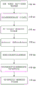
FIG. 10 is a flow chart depicting steps performed by a portable transmitter device when operating in accordance with a preferred method;
FIG. 11 is a flow chart depicting steps performed by a portable receiver device when operating in accordance with a preferred method;
FIG. 12 shows a schematic diagram of a preferred menu system on a watch;
FIG. 13 shows an example of a display screen that may be displayed by the watch for the menu system depicted in FIG. 12; and
FIG. 14 shows other exemplary ways of displaying the relative position of an athlete on a portable personal training device.
Like reference numerals are used for like features throughout the drawings.
Detailed Description
The preferred embodiments of the present invention will now be described with particular reference to a fitness or sports watch that utilizes Global Positioning System (GPS) data. Fitness or sports watches of the type described are typically worn by athletes to assist them during their running or exercising by monitoring their speed and distance and providing such information to the user. It will be appreciated, however, that the device may be arranged to be carried by a user or connected or "docked" in a known manner to a vehicle such as a bicycle, kayak or the like.
Fig. 1 illustrates an example view of a Global Positioning System (GPS) that may be used by such devices. Such systems are known and used for various purposes. In general, GPS is a satellite radio-based navigation system capable of determining continuous position, velocity, time, and in some cases, direction information for an unlimited number of users. Formerly known as navigational stars, the GPS incorporates a plurality of satellites that orbit the earth in extremely precise orbits. Based on these precise orbits, GPS satellites can relay their position to any number of receiving units.
The GPS system is implemented when a device specially equipped to receive GPS data begins scanning radio frequencies for GPS satellite signals. Upon receiving radio signals from the GPS satellites, the device determines the precise location of the satellites via one of a variety of different conventional methods. In most cases, the device will continue to scan for signals until it has acquired at least three different satellite signals (note that the position is determined for non-conventional with only two signals using other triangulation techniques, but this can be done). Geometric triangulation is performed, with the receiver using three known positions to determine its own two-dimensional position relative to the satellites. This can be done in a known manner. In addition, acquiring a fourth satellite signal will allow the receiving device to calculate its three-dimensional position by the same geometric calculations performed in a known manner. The position and rate data may be updated in real-time on a continuous basis by an unlimited number of users.
As shown in fig. 1, a GPS system is indicated generally by the reference numeral 100. A plurality of satellites 120 are in orbit about the earth 124. The orbit of each satellite 120 is not necessarily synchronized with the orbits of the other satellites 120 and, in fact, is likely to be out of synchronization. The GPS receiver 140 is shown receiving spread spectrum GPS satellite signals 160 from various satellites 120.
The spread spectrum signals 160 continuously transmitted from each satellite 120 utilize a highly accurate frequency standard achieved with a very accurate atomic clock. Each satellite 120 transmits, as part of its data signal transmission 160, a data stream indicative of that particular satellite 120. Those skilled in the art will appreciate that the GPS receiver device 140 typically acquires spread spectrum GPS satellite signals 160 from at least three satellites 120 for the GPS receiver device 140 to calculate its two-dimensional position by triangulation. Acquiring additional signals results in signals 160 from a total of four satellites 120 permitting the GPS receiver device 140 to calculate its three-dimensional position in a known manner.
Fig. 2 is an illustrative representation of the electronic components of a sports watch 200 in a frame component format in accordance with a preferred embodiment of the present invention. It should be noted that the block diagram of the device 200 does not include all of the components of the navigation device, but is merely representative of many example components.
The device 200 includes a processor 202, the processor 202 being connected to an input device 212, such as a depressible touch pad (or trackpad), and a display screen 210, such as an L CD display, the device 200 may further include an output device arranged to provide audible information to a user, such as a warning that a particular speed has been reached or a particular distance has been traveled.
Fig. 2 further illustrates the operative connection between the processor 202 and the GPS antenna/receiver 204. Although the antenna and receiver are schematically combined for illustration, they may be separate positioning components. The antenna may be of any suitable form but in a preferred embodiment is a GPS patch antenna.
The device 200 further includes an accelerometer 206, which accelerometer 206 may be a 3-axis accelerometer arranged to detect acceleration of the user in the x, y, and z directions. The accelerometer may serve as a number of steps for use in/under conditions where there is a loss of GPS reception and/or may be used to detect stroke rate when the fitness watch is used during swimming. Although the accelerometer is shown located within the device, the accelerometer may also be an external sensor worn or carried by the user, and which transmits data to the device 200 via the transmitter/receiver 208.
The device may also receive data from other sensors, such as a step frequency sensor 222 or a heart rate sensor 226. The step frequency sensor may be, for example, a piezoelectric or micro-electromechanical system (MEMS) accelerometer located in or on the sole of the user's shoe. Each external sensor is provided with a transmitter and receiver 224 and 228, respectively, which may be used to send or receive data to device 200 via transmitter/receiver 208.
The processor 202 is operatively coupled to the memory 220. Memory resources 220 may include, for example, volatile memory (e.g., Random Access Memory (RAM)), and/or non-volatile memory (e.g., digital memory, such as flash memory). The memory resource 220 may be removable. As discussed in more detail below, memory resources 220 are also operatively coupled to GPS receiver 204, accelerometer 206, and transmitter/receiver 208 for storing data obtained from these sensors and devices.
Furthermore, those skilled in the art will appreciate that the electronic components shown in FIG. 2 are powered by the power supply 218 in a conventional manner. The power source 218 may be a rechargeable battery.
The device 200 further includes an input/output (I/O) device 216, such as a plurality of electrical contacts or a USB connector. The I/O device 216 is operatively coupled to the processor, and is also operatively coupled to at least a memory 220 and a power supply 218. The I/O device 216 is used, for example, to: updating firmware of processor 220, sensors, etc.; transferring data stored on the memory 220 to an external computing resource (e.g., a personal computer or a remote server); and recharge the power supply 218 of the device 200. In other embodiments, data may also be sent or received wirelessly by device 200 using any suitable mobile telecommunications means.
As will be understood by those skilled in the art, different configurations of the components shown in fig. 2 may be considered within the scope of the present application. For example, the components shown in fig. 2 may communicate with each other via wired and/or wireless connections, and so on.
In fig. 3, the watch 200 is depicted as being in communication with a server 400 via a universal communication channel 410, which may be implemented by any number of different arrangements. When a connection is established between the server 400 and the watch 200, the server 400 and the device 200 may communicate (note that this connection may be a data connection via a mobile device, a direct connection via a personal computer via the internet, etc.).
The server 400 includes, among other components that may not be illustrated, a processor 404 operatively connected to a memory 406 and further operatively connected to a mass data storage device 402 via a wired or wireless connection. The processor 404 is further operatively connected to a transmitter 408 and a receiver 409 to transmit and send information to and from the device 200 via a communication channel 410. The sent and received signals may include data, communications, and/or other propagated signals. The functions of the transmitter 408 and the receiver 409 may be combined into a signal transceiver.
The communication channel 410 is not limited to a particular communication technology. Additionally, the communication channel 410 is not limited to a single communication technology; that is, channel 410 may include several communication links using a variety of techniques. For example, communication channel 410 may be adapted to provide a path for electrical, optical, and/or electromagnetic communication, among others. Thus, the communication channel 410 includes, but is not limited to, one or a combination of the following: electrical circuits, electrical conductors such as wire and coaxial cables, fiber optic cables, transducers, Radio Frequency (RF) waves, the atmosphere, space, and the like. Further, for example, the communication channel 410 may include intermediate devices such as routers, repeaters, buffers, transmitters, and receivers.
In one illustrative arrangement, the communication channel 410 includes telephone and computer networks. Further, the communication channel 410 may be capable of accommodating wireless communications, such as radio frequency, microwave frequency, infrared communications, and so forth. Additionally, the communication channel 410 may accommodate satellite communications.
The server 400 may be a remote server accessible through the watch 200 via a wireless channel the server 400 may include a network server located on a local area network (L AN), Wide Area Network (WAN), Virtual Private Network (VPN), and so on.
The server 400 may comprise a personal computer, such as a desktop or laptop computer, and the communication channel 410 may be a cable connected between the personal computer and the watch 200. Alternatively, a personal computer may be connected between the watch 200 and the server 400 to establish an internet connection between the server 400 and the watch 200. Alternatively, a mobile phone or other handheld device may establish a wireless connection to the internet for connecting the watch 200 to the server 400 via the internet.
The server 400 is further connected to (or includes) a mass storage device 402. The mass storage device 402 contains storage of at least digital map information. This digital map information may be used along with data from the device (e.g., time-stamped location data obtained from GPS receiver 204 and data indicative of the wearer's motion obtained from accelerometer 206, foot pad sensor 222, etc.) to determine a route traveled by the wearer of device 200, which may be viewed by the wearer.
As will be appreciated, the watch 200 is designed to be worn by a runner or other athlete while running or other similar types of exercise. Various sensors within the watch 200 (e.g., GPS receiver 204 and accelerometer 206) collect data associated with this run (e.g., distance traveled, current speed, etc.) and display this data to the user using the display screen 210.
Figure 4 shows a perspective view of a fitness watch case 502 in the form of a module that can be inserted into a variety of different docking solutions, according to a preferred embodiment of the present invention. The watch case 502 includes a display housing 504 and a user interface 506 spaced apart from one another. In the embodiment depicted in fig. 4, watch case 502 is inserted into apertures 513 and 514 in band 508 (as shown in fig. 7); the band may be worn on the user's wrist to form a fitness watch 500. As will be appreciated, user interface portion 506 of watch case 500 is arranged to pass through aperture 514, and display case portion 504 is arranged to pass through aperture 513. The strap 508 is formed of two parts 509, 510 connected to each other in a conventional manner by a buckle 512. Cooperating projections and recesses (e.g., projection 519 shown in figure 5) on watch case 500 and band 508 allow watch case 500 to be releasably engaged and maintained in position within band 508.
Figure 5 shows a perspective view of watch case 502 (once the module has been disengaged from band 508). As described above, the housing 502 has a display housing 504 and a user interface 506 spaced apart from the display housing. The display housing portion 504 is of substantially parallelepiped configuration and has a substantially planar display 516 for displaying information to a user. This part of the watch is located, in use, on the back of the user's wrist. The user interface portion 506 is connected to the display housing 504 by a connection portion 518. This connection portion 518 may be considered a flange that extends away from the display housing 504. The flange 518 bends as it extends away from the display housing 504 such that it bends around the side of the user's wrist in use. The user interface 506 is located on the flange 518 such that the user interface 506 is disposed on the side of the user's wrist in use. The user interface 506 has a substantially planar pressing surface for a user to interact with the watch 500. The user may thereby press the pressing surface in a direction perpendicular to the pressing surface in order to control the watch 500, e.g., select a desired function within a menu system of the watch.
The location of the user interface 506 which is arranged on the curved flange 518 such that it is disposed against the side of the user's wrist in use has several important advantages. For example, this enables a user to interact with the watch 500 using only a single finger. More specifically, the user can push the pressing surface of the user interface 506 with one finger because the user pushes the surface into the user's wrist around which the watch is cinched. This is in contrast to conventional watches in which buttons are arranged around the peripheral edge of the watch and the user must press the button with one finger and use the thumb on the other edge of the watch to counter the pressing force. Moreover, as will be described in more detail further below, the user interface 506 may define a chamber 536 (see fig. 8) that houses one or more other components, such as a GPS patch antenna 538. By configuring the GPS antenna 538 at the inner side of the wrist, the GPS antenna is located at an optimal position for receiving GPS signals when worn by a runner, since the inner side of the wrist will be oriented substantially upwards during running. As shown in fig. 10, the plane defined by the substantially planar display of the display housing 504 is arranged at an angle to the position defined by the user interface 506, the dihedral angle 550 between the two planes being less than 90 degrees, and typically between 40 and 70 degrees.
Figure 6 shows a perspective view of the watch case 502 from below the case. A flange 518 extending from the display housing 504 is disposed with an electrical connector 520 at a distal end thereof. These electrical connectors 520 may be used in order to electrically connect the case 502 to another device in order to recharge the battery within the watch case 502 or to extract data from the watch 500 or to input data to the watch 500. When the electrical connector 520 is arranged at the distal end of the flange 518, it is optimally arranged to be inserted into a slot of a docking device having a docking electrical connection for engaging the electrical connection 520 of the watch. Alternatively, the electrical connector 520 of the watch 500 may be arranged to connect with a cable. It will be appreciated that the removal of the strap 508 enables the watch 500 to be easily docked or connected to the cable electrical connector 520 for use as the input/output port 216 described with respect to fig. 2.
Fig. 8 shows a cross section through the case 502 of the watch and shows a preferred arrangement of the basic components of the watch.
The display housing portion 504 includes a battery (preferably, a rechargeable battery) 521, a liquid crystal display (L CD) display 522, a lens screen 524 above the L CD display 522, and a Printed Circuit Board (PCB)526 below the L CD display 522 the PCB526 will typically include a GNSS chipset operatively connected to a patch antenna 538 and arranged to process received micro signals to determine the position and speed of the device the PCB526 further includes a wireless communication device (e.g., a Bluetooth chipset) capable of using the Bluetooth Low energy (B L E) protocol forming part of the Bluetooth v4.0 specification and usable to form a connection with one or more external sensors (e.g., a heart rate monitor and a step frequency sensor) the display housing portion 504 also includes a pressure sensor 528 and a vibration device 530 the pressure sensor 528 is used to detect ambient pressure of the environment in which the watch 500 is located, for example, the sensor 528 may be used to detect underwater pressure and may relate this to an estimate of depth within water the watch 544 the pressure sensor 528 may be used to determine the altitude, the vibration device 528 is arranged adjacent to a lower housing of the vibration device to provide a warning to a user when the watch is worn from the lower housing 502, the lower housing, the vibration device, as a single watch case, a watch case, and a watch case, and a watch case, wherein the watch case, a watch case.
The user interface portion 506 defines a chamber 536 in which the watch components may be positioned. The chamber 536 may be defined by the button bezel 532 and the lower casing 544. The patch antenna 538 is located in the chamber 536. As described above with respect to fig. 5, this arrangement enables the antenna 538 to be placed on the medial side of the user's wrist and thus enables the GPS antenna 538 to be oriented naturally upward when worn during running. This is in contrast to conventional sports watches in which the GPS antenna is arranged below the display. Because the display in such conventional watches is designed to sit on the back of the user's wrist, the display, and thus the GPS antenna, cannot face upward while the user is running and is therefore not in the optimal position to receive GPS signals. The preferred location of the GPS antenna 538 on the exterior of the display case portion 504 in accordance with embodiments of the present invention also enables the size of the watch case portion 504 to be reduced for a given number of components. The electronics in the user interface portion 506 are electrically connected to the electronics in the display housing portion 504, such as by a ribbon cable 540.
The user interface portion 506 includes a touchpad (or trackpad) 532 that utilizes, for example, capacitive sensing to conductance sensing to convert the motion of a user's finger into input to control the watch. The touch panel may comprise a one-dimensional touch panel, and the one-dimensional catalyst plate is capable of sensing motion along a single axis (e.g., left-right or up-down). In other more preferred embodiments, touchpad 532 comprises a two-dimensional touchpad and the two-dimensional catalyst plate is capable of sensing motion in any direction or at least side-to-side and up-and-down on a plane defined by the substantially planar surface of the input means. The touchpad 532 is further configured to be depressible, for example for use in selecting a desired function within a menu system of the watch. This enables the user to operate the user interface with a single finger. The user does not need to use the second finger of the same hand to counter the pressing of the user interface, as the user interface is arranged such that it is pressed against the wrist of the user wearing the watch. As shown in fig. 8, depression of the catalyst plate is detected by a sensor 534, which sensor 534 converts the detected motion into an electrical signal for transmission via a ribbon cable 540 to the associated components within the display housing 504.
In other embodiments, user interface portion 506 may utilize other types of input means, such as a pointing stick that senses the force applied by a user's finger, such as by using a pair of resistive strain gauges, and converts it into an input to control a watch. Alternatively, the input means may comprise a bi-directional button of a continuous pressing surface and two actuators, the button being configured such that a first one of the actuators is actuated so as to provide a first input to control the watch when a first portion of the pressing surface is depressed, and a second one of the actuators is actuated so as to provide a second input to control the watch when a second portion of the pressing surface is depressed. Alternatively, the input means may comprise a four-way button having a continuous pressing surface and four actuators, the button being configured such that a first one of the actuators is actuated so as to provide a first input to control the watch when a first portion of the pressing surface is depressed, a second one of the actuators is actuated so as to provide a second input to control the watch when a second portion of the pressing surface is depressed, a third one of the actuators is actuated so as to provide a third input to control the watch when a third portion of the pressing surface is depressed, and a fourth one of the actuators is actuated so as to provide a fourth input to control the watch when a fourth portion of the pressing surface is depressed. The pressing surface described herein is preferably the substantially planar surface parallel to and above the portion of the lower surface which, in use, contacts the user's arm or wrist. It is also contemplated that the user interface may optionally include any one or more mechanically actuated buttons or non-mechanically actuated buttons, such as virtual buttons on a touch sensitive user interface.
According to a preferred embodiment of the present invention, the first sports watch communicates sensor data to at least one other sports watch and the first sports watch may also receive sensor data from the at least one other sports watch. The sensor data may be, for example, location data indicative of a location of a sports watch that transmitted the data. This enables the first sports watch to communicate its location to the other sports watches so that each of the users of the other sports watches can compare its location to the location of the first sports watch. Similarly, the first sports watch may receive location data from the other sports watches such that the first sports watch is capable of indicating a location of each of the other sports watches relative to the first sports watch. This may be useful, for example, if users of such sports watches are competing against one another in a competition. Sports watches typically include a position determining means (e.g., a GPS receiver) to detect their position and optionally current speed. Thus, the sensor data is preferably position and/or velocity information from a GPS receiver. However, other types of sensor data may be transmitted in addition to or instead of location information. For example, each sports watch may be associated with a speed (or velocity) sensor or an altitude sensor, and data from at least one of these sensors may be transmitted to the other watches.
Preferably, the sports watch uses a Bluetooth protocol (such as the Bluetooth Low energy (B L E) protocol, which may be a feature of the Bluetooth v4.0 specification) to transfer sensor data to other sports watches.
A Bluetooth device operating according to the B L E protocol has five basic operating states, which are a standby state, an advertising state, a scanning state, an initialization state, and a connected state.
FIG. 9 shows a first device 550 and a second device 552 that want to pass data between each other, the first device 550 moving from its standby state to an advertising state and broadcasting an advertising channel packet with an advertising Protocol Data Unit (PDU). the B L E protocol has four initialization advertisement time types, three of which are non-targeted (i.e., not intended for a particular receiver) and one is targeted.the three depicted non-targeted advertisement event types of FIG. 9 are (i) a connectable non-targeted (ADV _ IND) event that allows a scanner or an initiator to respond with a SCAN request or a connection request, (ii) a scannable non-targeted (ADV _ SCAN _ IND) event that allows a scanner to respond with a SCAN request to request additional information about an advertising device, and (iii) a non-connectable non-targeted (ADV _ NONCONN _ IND) event that allows a scanner to receive additional information included in a packet from an advertising device but may include any additional information included in the address of the selected arrow packet in the advertising channel packet and/or any additional data packet that is not included in the advertising device data packet.
The second device 552 moves from its standby state to a scanning state in which it listens for advertising packets. The second device 552 has a scanner screening policy that defines which advertising channel packets it will process. It may be configured to process advertising channel packets from a "white list" of selected devices or it may be configured to process all received advertising channel packets. The manner in which the advertising channel packets broadcast by the first device 500 are processed by the second device 502 depends on the type of advertising channel packet received. Thus, for example, in the case that a non-targeted advertising event packet may be connected, the second device 552 may broadcast a SCAN request (SCAN _ REQ) data packet or a connection request (CONNECT _ REQ) packet. In the case of a scannable non-targeted ad event package, the second device 552 broadcasts a scan request package. Finally, in the case of a connectionless non-directed event, the second device 552 processes the received packet but does not broadcast the packet in response. The scan request and the connection request packet each include addresses of the first device 550 and the second device 552.
In a manner similar to the second device 552, the first device 550 has an advertisement screening policy that defines how the device will handle any received scan or connection request packets. For example, the first device 550 may be configured to process received scan or connection request packets from a "white list" of selected devices or it may be configured to process all received scan or connection request packets. If the SCAN request packet sent from the second device 552 is processed by the first device 550, the first device 550 will send a SCAN response (SCAN _ RSP) packet back to the second device 552. The scan response packet includes the address of the first device 550 and may again include additional data selected by the advertising device. If the received connection request packet is processed by the first device 550, the first device 550 will form a data connection to the second device 552. The PDU of the connection request message defines several parameters used during communication between the first device 500 and the second device 502, such as the transmission window size and the timeout duration. The term "data connection" as used herein means that the transceivers of both the first device 500 and the second device 502 are tuned to the same frequency channel and use the same access address of the channel at the same time. The second device 502 then operates in the master role and the first device 500 operates in the slave role. The data desired to be transmitted between the two devices is then transmitted over the data channel established by the data connection.
The conventional communication methods described above are relatively low power methods of wirelessly communicating data. However, the power requirements of such a technique are still undesirably high for some applications. For example, sports watches such as those described above have relatively low capacity batteries and GNSS positioning systems (e.g., GPS receivers) in such watches require a large proportion of the energy available from the battery. It is therefore desirable to transfer data in a more energy efficient manner.
According to the present invention, sensor data can be transferred between devices in a more energy efficient manner than conventionally done. The inventors have recognized that sensor data can be transmitted between devices without establishing a data connection between the two devices (i.e., without simultaneously tuning the transceivers of the two devices to the same frequency channel) and that the data can thus be transferred in a less power-intensive manner. More specifically, the inventors have recognized that sensor data tends to be relatively small and that it may only be necessary to communicate sensor data to other devices at periodic and infrequent intervals, and that the sensor data may thus be transmitted in advertising channel packets, and in particular as optional additional data that may be added by the advertising device to the initial advertising channel packets and scan response data packets for each of the three non-targeted advertising event types.
The preferred method will now be described with reference to fig. 10 and 11, where the first and second devices are sports watches and the sensor data is GNSS position and/or velocity data, however, it will be appreciated that the invention is also applicable to other types of devices and other types of sensor data in the preferred method the sports watch utilizes a bluetooth protocol to transfer data to each other, such as the B L E protocol, the first watch obtains GNSS position and/or velocity data indicative of the position and/or velocity of the first watch by using its GNSS receiver (step 560), the first watch then adds this sensor data to a PDU of an advertising channel packet ADV _ n _ IND or hand ADV _ non _ IND which may be broadcast from the first watch when in an advertising state (step 561), using one of these two advertising event types, as none may cause a data connection to be established between the first watch and another in the broadcast range of the first watch and receive an advertising channel packet (step 570) and the first watch, if such a data packet is not available, it is able to be transferred from the first watch to the second watch, and it is able to be transferred from the second watch, or to be transferred to the second watch, such a mobile device, and the second watch device is able to process the data packet, such a bluetooth data transfer data packet, and the second watch, if the current mobile device is able to be transferred from the second watch.
As discussed above, if the ADV SCAN IND packet is received by the second watch, it may broadcast the SCAN request packet SCAN REQ to the first device in response to the advertisement channel packet received from the first watch. The first watch may then broadcast a SCAN response data packet SCAN _ RSP in response to the SCAN request packet received from the second watch (steps 563 and 566). The first watch may add its address (i.e., identity) and updated GNSS position and/or velocity data from the GNSS receiver into the PDU portion of the scan response packet (steps 564 and 565). As such, when the second watch receives a scan response packet from the first watch, the second watch may extract the address (i.e., identity) of the first watch and the updated GNSS position and/or velocity data sent from the first watch. The second watch is then able to update the current location and/or velocity information of the first watch and may indicate to a user of the second watch the new location and/or velocity of the first watch relative to the second watch or the updated distance between the two watches. Alternatively, or in addition to the updated GNSS position and/or velocity data in the scan response packet, the first watch may also add another type of sensor data to the scan response packet to be sent to the second watch.
It will be appreciated that the sensor data may be sent in only one of the advertising channel packets and the scan response messages, or any combination of two or more thereof. It will also be appreciated that the second watch may operate in an advertising state and the first watch may operate in a scanning state. The second watch may thus send sensor data to the first watch in a manner corresponding to that described in which the first watch sent the sensor data to the second watch (i.e., in the advertising channel packet and the scan response message).
The first and second watches do not form a data connection channel therebetween in order to transfer the sensor data. This is prevented by the watches using a message format that only enables the watches to operate in advertising, scanning, or standby states and that does not send connection request messages between the watches.
Although only two devices are described, the present invention may be used to transfer data to additional devices. For example, the third or additional watch may transmit sensor data to the first and/or second watches in the same manner as described above with respect to the first and second watches communicating data to each other. Similarly, the first and/or second watches may transfer data to the third watch in the same manner as described above with respect to the first and second watches transferring data to each other. It will thus be appreciated that each of the watches will be able to display the location of a plurality of other watches, provided that they are within range.
Each watch may be arranged to process advertisement channel packets, scan request messages, or scan response messages from all other devices. The slave feature will enable each watch to display sensor data from any other watch within range. Alternatively, each watch may be set to process advertisement channel packets, scan request messages, or scan response messages only from selected devices (i.e., devices on the "white list"). This feature would enable each watch to display only sensor data from a particular other watch (e.g., a watch from the same manufacturer). The user of each watch may be able to select the device from which to process the advertising channel packets, scan request messages, or scan responses. For example, the user may choose to only process advertisement channel packets, scan request messages, or scan responses from individual watches (e.g., watches of known competitors or acquaintances).
It will be appreciated that the sensor data will be broadcast between the watches at a suitable frequency to allow the user of the watch to be informed about the status of their competitors. For example, the advertising channel data packet and additional sensor data may be broadcast periodically once every 30 seconds to 2 minutes, or at a rate that depends on the speed at which the user is traveling. For example, it would be desirable to transfer sensor data at a faster rate between rider groups than a pedestrian group.
As described above, the user interface portion 506 of an exemplary watch arranged to operate using the methods of embodiments of the present invention comprises a trackpad across the surface of which movement of a user's finger can be detected in two dimensions. This is particularly useful for navigating a menu system displayed by display 522. Embodiments of the present invention preferably use a "multidimensional dataset" to design a menu system, such as the menu system shown in FIG. 12. The "multidimensional dataset" menu system is so called because it resembles the structure of a multidimensional dataset in the condition that the multidimensional dataset is not spread out across the multidimensional dataset.
FIG. 12 shows a general schematic diagram of the menu system and FIG. 13 shows an example of the types of content that may be included in each portion of the menu system. As shown in fig. 12 and 13, the display may have a default main screen 600 that may display a clock or other information. The user can indicate up, down, left or right movement on the movement of the trackpad 532 in order to navigate four different paths of the menu system. In this example, if the user moves their finger to the left across the touchpad 532, the screen navigates to a status page 602, which may display status information such as battery remaining capacity, available storage capacity, GPS reception level, installed software version, or serial number of the watch 500.
In this example, if the user moves their finger up across the touch pad 532, the screen navigates from the home page 600 to the smart phone page 604. This page of the menu system can be used to initiate or extend a connection with the smartphone.
In this example, if the user moves their finger down across the touch pad 532, the screen navigates from the home page 600 to the settings page 606. This enables the user to check or change the settings of the watch 500. For example, a user may view or change a watch profile, a clock, a watch sensor, or connectivity (e.g., between an airplane flight mode and a non-flight mode). The user may navigate up and down through the settings menu by appropriate motion across the trackpad 532, and may select which settings to view or change by using left or right movement across the trackpad 532 or by depressing the trackpad 532. This may guide the user to additional menu pages not illustrated in fig. 12 and 13.
In the example shown, if the user moves their finger to the left across the trackpad 532, the screen navigates from the home page 600 to the application menu 608. The user may then select the type of mode that they wish to use the watch. For example, the user may select a running mode, a cycling mode, a swimming mode (e.g., a pool mode and/or a open-air swimming mode), or a triathlon mode. The user may navigate up and down through the application menu by appropriate motion across the trackpad 532, and may select which mode to use by using left or right motion across the trackpad 532 or by depressing the trackpad 532. This guides the user to the application content page 610. In the example shown in FIG. 13, the running mode has been selected and the application content page is configured for the running mode. Once the GPS location of the device has been determined, the watch will display a running page 612 showing the stride, the distance traveled (top left) and the estimated calories used (top right).
FIG. 13 shows four other displays that may be displayed by the watch once the training mode has been selected. The watch 500 may indicate a warning to the user, for example, when the user starts a new lap or when the user has reached a particular target (target/goal). This warning may be provided to the user through the speaker 214 on the watch, through the display 210, 522 of the watch 500, or through the vibration device 530 of the watch.
Screen 614 shows a "goal" mode in which the user has indicated the distance of the goal that the user wishes to travel and the watch displays the distance to the goal from the current location. In the illustrated example, the user has input to the watch that the goal is to travel 10km and the watch indicates that the distance from the current location to conducting this 10km is 7.5 km.
Screen 616 shows a "best athletics (zone)" mode in which the watch displays the user's heart rate. The display also shows a bar graph of the degree of change in the user's heart rate over time relative to the target heart rate selected by the user.
Screen 618 shows a "circle" mode, which displays the number of turns of the circle the user has traveled. For example, the watch may count the number of laps of a swimming pool that the user has traveled or a predefined distance of running, such as around a conventional 400m runway.
The screen 620 shows a "compete with me" mode, this display is similar to that of the goal mode 614, except that there is a second arrow to indicate the location of another competitor that is competing with the user the total distance of the competition is shown in a manner similar to the goal mode 614, but in this example the competition distance is only 2.3 km. the distance between the user and the competitor is also shown and in this example is 23m the second arrow may represent a virtual competitor whose progress is generated by the watch 500, e.g., based on requirements previously input by the user.
The "compete with me" mode screen 620 described above is one example of indicating the current relative record and/or speed between competitors. Another example will now be described with reference to fig. 14. As shown in fig. 14, each watch may have a radar-type screen 700 that shows the relative positions of all other watches that have been detected (i.e., from which advertising channel packets have been processed). The location of each watch may be indicated by a unique icon 702, 704, 706 that may be picked by the user of the respective watch and communicated along with the sensor data. The display of any given watch may show the location of other watches relative to the compass direction on the given watch so that the direction of the location of other watches may be determined by the user of the watch regardless of the angle from which the watch is viewed. The watch's own location may always be displayed at a predetermined point (e.g., the center of the radar-type screen 700) or by its own unique icon. The distance from this point on the display or icons of other detected watches may be proportional to the actual distance to other watches. The watch may only indicate other watches that are detected to be within a predetermined distance. Alternatively, a watch detected to be at a distance greater than the predetermined distance may be indicated by icon 708 at the maximum distance on the display, e.g., at a point on a ring at the edge of the display.
Alternatively, any given watch may be configured such that a user may select one of the other detected watches to remain at a predetermined location on the display and show its own location for the given watch as moving relative to the predetermined location as the given watch moves relative to the other detected watches.
Each watch receives identity and sensor data from the other watches. Each watch may be configured to transfer the identity and sensor data received from the other watches (and preferably in the same manner) when it transfers its own identity and sensor data to another watch or other watches. In this manner, the watch is able to receive identity and sensor data from other watches outside its range, since this information is retransmitted by watches that are within range. This serves to increase the range of the network without the need for a high power transceiver.
If no other watches are detected for the predetermined length of time, the icons of these watches may be detached from the display or may be indicated as not having been detected for the predetermined length of time, e.g., by being shown as faded icons.
The watch may be configured such that the user may select an icon of another watch and determine data about the other watch. For example, a user may be able to determine more information about the identity of the user of the other watch, such as their full name or additional details about their location. This additional data may be received by the watch in the same manner as the sensor data. Alternatively, or in addition, the watch may indicate more details of detecting the last known location and/or the last time of other watches.
Another exemplary use of the present invention will now be described with reference to a group of riders traveling in a master vehicle crowd (peloton). In this case, each rider in the host group may be associated with a watch configured to communicate data indicative of their identity and location, such as by reference to the rider's location in the host group in the manner discussed above. For example, one or more warnings may be communicated to the rider in the form of audio and/or visual and/or tactile alerts based on their position in the host vehicle group relative to other riders. For example, a warning may be conveyed to the user as they turn to move to the front of the main vehicle group. Warnings may also be conveyed to the user when one or more riders fall behind the main vehicle group. It will be understood that similar functionality may be provided in other activities where a group of users needs to travel in some formation type.
It should be understood that while various aspects and embodiments of the present invention have been described thus far, the scope of the present invention is not limited to the particular arrangements set forth herein but extends to cover all arrangements and modifications and alterations thereto which fall within the scope of the appended claims.
For example, although the embodiments described in the above detailed description relate to GPS, it should be noted that the navigation device may utilize any kind of position sensing technology as an alternative to (or indeed in addition to) GPS. For example, the navigation device may utilize the use of other global navigation satellite systems (e.g., the european galileo system). Again, it is not limited to satellite-based systems, but can function readily using ground-based beacons or any other kind of system that enables a device to determine its geographic location.
Although the preferred method has been described with respect to the transmitted sensor data being location data, additional or alternative types of sensor data may be transmitted. For example, data from any one or combination of a speed sensor, a velocity sensor, an orientation sensor, or an altitude sensor may be communicated. The device to which this data is transferred may display this data from other devices, or may display differences between this sensor data and the corresponding sensor data of the device to which the data has been transferred, for example, displaying differences in speed, orientation or altitude.
Although the preferred method has been described in relation to a sports watch, it will be appreciated that sensor data may be communicated to and from any other type of device using the method of the present invention. Other devices, such as other personal training or mobile devices, may use the present invention. For example, a mobile phone may have installed thereon an application that operates in the manner of the present invention.
Although the preferred method has been described with respect to bluetooth communications, the present disclosure contemplates other short range communication techniques and protocols (e.g., within a broadcast range of approximately 100m or less) in which one device operates in an advertising mode to broadcast data packets and another device operates in a scanning mode to receive and process such data packets without forming a data connection between the devices.
It will also be well understood by those skilled in the art that while the preferred embodiment implements certain functionality by means of software, the functionality could equally be implemented solely in hardware, for example by means of one or more SIC's (application specific integrated circuits), or indeed by a mix of hardware and software.
Finally, it should also be noted that although the appended claims set forth particular combinations of features described herein, the scope of the present invention is not limited to the particular combinations claimed below, but instead extends to cover any combination of features or embodiments disclosed herein, whether or not that particular combination is specifically enumerated in the appended claims at this time.
Claims (20)
1. A portable device, comprising:
at least one sensor device;
a transmitter;
a receiver;
a processor; and
an output device, wherein the portable device is configured to:
obtaining first sensor data from the at least one sensor device, the first sensor data being representative of at least one property of the portable device and/or a user associated with the portable device;
operating in an advertising state in which the processor is arranged to: assembling the first sensor data together with a first identifier for identifying the portable device into a first data packet; and control the transmitter to wirelessly broadcast the first data packet to one or more other portable devices;
operating in a scan state in which the processor is arranged to: scanning, using the receiver, second data packets wirelessly broadcast by the one or more other portable devices, wherein each second data packet includes second sensor data and a second identifier for identifying the other portable device that transmitted the second data packet, wherein the second sensor data is representative of at least one property of the respective other portable device and/or a user associated with the respective other portable device; and, when the receiver receives a second data packet, determining the identity of the other portable device from the second identifier in the received second data packet and extracting the second sensor data from the received second data packet; and
providing an output using the output device to indicate: (1) the identity of the other portable device; and (2) the first sensor data and the second sensor data, or a relative difference between the first sensor data and the second sensor data.
2. The portable device of claim 1, wherein the processor is arranged to periodically and repeatedly perform the steps of: assembling the first sensor data together with the first identifier for identifying the portable device into the first data packet; and controlling the transmitter to wirelessly broadcast the first data packet to the one or more other portable devices.
3. The portable device of claim 1, wherein the portable device is configured to communicate the first sensor data to the one or more other portable devices in the first data packet without performing at least one of: is required to detect the one or more other portable devices; and must establish a data connection with the one or more other portable devices by being simultaneously tuned to the same channel.
4. The portable device of any of the preceding claims, wherein the transmitter is configured to broadcast the first data packet using a bluetooth protocol, and wherein the first data packet is a bluetooth advertising channel packet and the processor is configured to add the first identifier and first sensor data to the bluetooth advertising channel packet.
5. The portable device of any of claims 1-3, wherein the transmitter is configured to broadcast the first data packet using a Bluetooth Low energy protocol.
6. The portable device of any of claims 1-3, wherein the first sensor data and the second sensor data represent one or more of: a geographic location; speed; orientation; acceleration; altitude; and heart rate.
7. A portable device according to any of claims 1 to 3, wherein the output device is arranged to provide output by at least one of audibly, visually or tactilely.
8. The portable device of any of claims 1-3, wherein the receiver is configured to scan and receive the second data packet using a Bluetooth protocol, and wherein the processor is configured to extract the second identifier and the second sensor data from a received Bluetooth advertisement data packet.
9. The portable device of any of claims 1-3, wherein the output device comprises a display device and the output comprises an icon representing the identity of the other portable device.
10. The portable device of any of claims 1-3, wherein the portable device is configured to only extract and provide the second sensor data from a second data packet received from a portable device having an identity on a predefined list of identities.
11. The portable device of claim 10, wherein the predefined list of identities is modifiable by a user.
12. The portable device of any of claims 1-3, wherein the portable device is a personal training device.
13. A method of operating a portable device, the portable device comprising: at least one sensor device; a transmitter; a receiver; a processor; and an output device, the method comprising:
obtaining first sensor data from the at least one sensor device, the first sensor data being representative of at least one property of the portable device and/or a user associated with the portable device;
operating the portable device in an advertising state in which the processor is arranged to: assembling the first sensor data together with a first identifier for identifying the portable device into a first data packet; and control the transmitter to wirelessly broadcast the first data packet to one or more other portable devices;
operating the portable device in a scanning state in which the processor is arranged to: scanning, using the receiver, second data packets wirelessly broadcast by the one or more other portable devices, wherein each second data packet includes second sensor data and a second identifier for identifying the other portable device that transmitted the second data packet, wherein the second sensor data is representative of at least one property of the respective other portable device and/or a user associated with the respective other portable device; and, when the receiver receives a second data packet, determining the identity of the other portable device from the second identifier in the received second data packet and extracting the second sensor data from the received second data packet; and
providing an output using the output device to indicate: (1) the identity of the other portable device; and (2) the first sensor data and the second sensor data, or a relative difference between the first sensor data and the second sensor data.
14. The method of claim 13, comprising periodically and repeatedly performing the steps of: assembling the first sensor data together with the first identifier for identifying the portable device into the first data packet; and controlling the transmitter to wirelessly broadcast the first data packet to the one or more other portable devices.
15. The method of claim 13, comprising communicating the first sensor data to the one or more other portable devices in the first data packet without performing at least one of: is required to detect the one or more other portable devices; and must establish a data connection with the one or more other portable devices by being simultaneously tuned to the same channel.
16. The method of any one of claims 13 to 15, comprising broadcasting the first data packet using a bluetooth protocol, and wherein the first data packet is a bluetooth advertisement channel packet, the method comprising adding the first identifier and first sensor data to the bluetooth advertisement channel packet.
17. The method of any of claims 13 to 15, comprising receiving the second data packet using a bluetooth protocol, and extracting the second identifier and the second sensor data from the received bluetooth advertisement data packet.
18. The method of any one of claims 13 to 15, comprising extracting and providing only the second sensor data from a second data packet received from a portable device having an identity on a predefined list of identities.
19. The method of claim 18, wherein the predefined list of identities is modifiable by a user.
20. A non-transitory computer readable medium comprising computer readable instructions that, when executed on a processor of a portable device, cause the portable device to perform a method of operating a portable device, the portable device comprising: at least one sensor device; a transmitter; a receiver; a processor; and an output device, the method comprising:
obtaining first sensor data from the at least one sensor device, the first sensor data being representative of at least one property of the portable device and/or a user associated with the portable device;
operating the portable device in an advertising state in which the processor is arranged to: assembling the first sensor data together with a first identifier for identifying the portable device into a first data packet; and control the transmitter to wirelessly broadcast the first data packet to one or more other portable devices;
operating the portable device in a scanning state in which the processor is arranged to: scanning, using the receiver, second data packets wirelessly broadcast by the one or more other portable devices, wherein each second data packet includes second sensor data and a second identifier for identifying the other portable device that transmitted the second data packet, wherein the second sensor data is representative of at least one property of the respective other portable device and/or a user associated with the respective other portable device; and, when the receiver receives a second data packet, determining the identity of the other portable device from the second identifier in the received second data packet and extracting the second sensor data from the received second data packet; and
providing an output using the output device to indicate: (1) the identity of the other portable device; and (2) the first sensor data and the second sensor data, or a relative difference between the first sensor data and the second sensor data.
Applications Claiming Priority (3)
| Application Number | Priority Date | Filing Date | Title |
|---|---|---|---|
| GB13042197 | 2013-03-08 | ||
| GBGB1304219.7A GB201304219D0 (en) | 2013-03-08 | 2013-03-08 | Methods for communicating sensor data between devices |
| PCT/EP2014/054613 WO2014135711A1 (en) | 2013-03-08 | 2014-03-10 | Methods for communicating sensor data between devices |
Publications (2)
| Publication Number | Publication Date |
|---|---|
| CN105210420A CN105210420A (en) | 2015-12-30 |
| CN105210420B true CN105210420B (en) | 2020-07-21 |
Family
ID=48189605
Family Applications (1)
| Application Number | Title | Priority Date | Filing Date |
|---|---|---|---|
| CN201480025328.7A Active CN105210420B (en) | 2013-03-08 | 2014-03-10 | Method for transferring sensor data between devices |
Country Status (6)
| Country | Link |
|---|---|
| US (1) | US10321293B2 (en) |
| EP (1) | EP2965563B1 (en) |
| JP (1) | JP6340377B2 (en) |
| CN (1) | CN105210420B (en) |
| GB (1) | GB201304219D0 (en) |
| WO (1) | WO2014135711A1 (en) |
Families Citing this family (58)
| Publication number | Priority date | Publication date | Assignee | Title |
|---|---|---|---|---|
| EP2680931A4 (en) | 2011-03-04 | 2015-12-02 | Eski Inc | Devices and methods for providing a distributed manifestation in an environment |
| WO2016000225A1 (en) * | 2014-07-02 | 2016-01-07 | Intel Corporation | Method, apparatus and system for exchanging sensor information with middleware |
| CN105451184A (en) | 2014-09-30 | 2016-03-30 | 阿里巴巴集团控股有限公司 | Wireless communication method and device |
| GB201420610D0 (en) * | 2014-11-20 | 2015-01-07 | Suunto Oy | Ad-hoc events |
| US10356189B2 (en) * | 2014-11-20 | 2019-07-16 | Suunto Oy | System and method for creating ad-hoc events from sensed sport-specific data |
| JP6590486B2 (en) | 2015-02-18 | 2019-10-16 | キヤノン株式会社 | Program, method, communication terminal |
| US9849336B2 (en) * | 2015-02-27 | 2017-12-26 | Polar Electro Oy | Team sport monitoring system |
| JP6477133B2 (en) | 2015-03-27 | 2019-03-06 | ブラザー工業株式会社 | Communication equipment |
| CA2928057C (en) * | 2015-04-22 | 2022-05-24 | Staples, Inc. | Intelligent item tracking and expedited item reordering by stakeholders |
| EP3125641B1 (en) | 2015-07-31 | 2021-07-21 | Nintendo Co., Ltd. | Wireless system, wireless device, non-transitory computer-readable storage medium having stored therein communication program, and communication method |
| US10397868B2 (en) * | 2015-07-31 | 2019-08-27 | Nintendo Co., Ltd. | Wireless system, wireless device, non-transitory computer-readable storage medium having stored therein communication program, and communication method |
| JP6625887B2 (en) | 2015-07-31 | 2019-12-25 | 任天堂株式会社 | Wireless system, wireless device, communication program, and communication method |
| US10827735B2 (en) * | 2015-09-19 | 2020-11-10 | Vulture Systems, LLC | Remotely detectable transportable game and fishing alarm system |
| US9974050B2 (en) | 2015-12-16 | 2018-05-15 | Verily Life Sciences Llc | Transmitter IC for single-channel Bluetooth beacon |
| CN105635943B (en) * | 2015-12-21 | 2020-02-28 | 中颖电子股份有限公司 | Low-power-consumption Bluetooth beacon data interaction device, beacon device and method |
| JP6769036B2 (en) * | 2016-01-29 | 2020-10-14 | セイコーエプソン株式会社 | Wearable devices and communication systems |
| US10412570B2 (en) * | 2016-02-29 | 2019-09-10 | Google Llc | Broadcasting device status |
| US9999025B2 (en) | 2016-03-08 | 2018-06-12 | Verily Life Sciences Llc | Beacon using an FBAR-based oscillator |
| CN105956463B (en) * | 2016-04-23 | 2019-01-11 | 腾讯科技(深圳)有限公司 | A kind of apparatus control method, device and terminal |
| US10212657B2 (en) | 2016-04-27 | 2019-02-19 | Verily Life Sciences Llc | Bluetooth low energy beacon with FBAR-based oscillator-per-channel |
| JP6741496B2 (en) * | 2016-06-30 | 2020-08-19 | キヤノン株式会社 | Communication device, control method thereof, program, and storage medium |
| US10097387B1 (en) | 2016-08-15 | 2018-10-09 | Verily Life Sciences Llc | Temperature-stable FBAR transmitter |
| WO2018045446A1 (en) | 2016-09-07 | 2018-03-15 | Eski Inc. | Projection systems for distributed manifestation and related methods |
| US9959434B1 (en) | 2016-10-08 | 2018-05-01 | Ospicon Systems Pte Ltd | Bi-directional communication system for logistic tracking |
| WO2018067064A1 (en) * | 2016-10-08 | 2018-04-12 | Ospicon Systems Pte Ltd | Bi-directional communication system for logistic tracking |
| CN106792470A (en) * | 2016-12-29 | 2017-05-31 | 中国南方电网有限责任公司超高压输电公司南宁局 | A kind of electric inspection process data automatic input system and method |
| US10779238B2 (en) | 2017-03-02 | 2020-09-15 | Carrier Corporation | Access control system with dynamic performance tuning |
| EP3589808A1 (en) | 2017-03-02 | 2020-01-08 | Carrier Corporation | Access control system with dynamic performance tuning |
| CN108696293B (en) * | 2017-03-03 | 2020-11-10 | 株式会社理光 | Wearable device, mobile device and connection method thereof |
| GB201707050D0 (en) * | 2017-05-03 | 2017-06-14 | British American Tobacco Investments Ltd | Data communication |
| US10627525B2 (en) * | 2017-05-10 | 2020-04-21 | Qualcomm Incorporated | Water-related action triggering |
| EP3442199B1 (en) * | 2017-08-07 | 2021-04-14 | Nokia Technologies Oy | Apparatus for determining the presence of a resource and a method |
| JP2019033454A (en) * | 2017-08-09 | 2019-02-28 | オムロンヘルスケア株式会社 | Data transmission system and data transmission device therefor, and data reception device |
| JP2019033450A (en) * | 2017-08-09 | 2019-02-28 | オムロンヘルスケア株式会社 | Information processing system, data transmitting apparatus, data receiving apparatus, information processing method, and program |
| JP6925907B2 (en) * | 2017-08-09 | 2021-08-25 | オムロンヘルスケア株式会社 | Data transmitters, data receivers, methods and programs |
| JP2019033449A (en) * | 2017-08-09 | 2019-02-28 | オムロンヘルスケア株式会社 | Data transmitting apparatus, data receiving apparatus, method, and program |
| US20190075518A1 (en) * | 2017-09-07 | 2019-03-07 | Qualcomm Incorporated | Systems and methods for low power operation of a wireless communication device |
| US11600365B2 (en) | 2017-12-12 | 2023-03-07 | Vyaire Medical, Inc. | Nasal and oral respiration sensor |
| CN108320487B (en) * | 2017-12-28 | 2021-11-16 | 臻迪科技股份有限公司 | Underwater equipment communication method and system |
| GB201722278D0 (en) | 2017-12-29 | 2018-02-14 | British American Tobacco Investments Ltd | Device identification and method |
| US10715528B1 (en) * | 2018-01-31 | 2020-07-14 | Amazon Technologies, Inc. | Multi-factor location-based and voice-based user location authentication |
| US10735411B1 (en) | 2018-01-31 | 2020-08-04 | Amazon Technologies, Inc. | Multi-factor location-based authentication |
| US11134446B2 (en) | 2018-02-05 | 2021-09-28 | Abbott Diabetes Care Inc. | Systems, devices, and methods for power-efficient wireless communications between electronic devices |
| US11315174B2 (en) | 2018-05-29 | 2022-04-26 | Staples, Inc. | Restocking hub with interchangeable buttons mapped to item identifiers |
| WO2019243316A1 (en) * | 2018-06-21 | 2019-12-26 | Assa Abloy Ab | Remote lock unlocking |
| CN109348433A (en) * | 2018-11-23 | 2019-02-15 | 深圳市椰壳信息科技有限公司 | A kind of sensor information sharing method and system based on Bluetooth broadcast |
| CN109640308B (en) * | 2019-01-23 | 2023-07-04 | 成都怡康科技有限公司 | Bracelet wireless communication system and method thereof |
| FI3982821T3 (en) * | 2019-06-11 | 2024-03-25 | Sunmed Group Holdings Llc | Nasal and oral respiration sensor |
| US11779724B2 (en) | 2019-06-11 | 2023-10-10 | Sunmed Group Holdings, Llc | Respiration sensor attachment device |
| JP6915178B2 (en) * | 2019-09-12 | 2021-08-04 | キヤノン株式会社 | Programs and communication terminals |
| JP6828111B2 (en) * | 2019-09-12 | 2021-02-10 | キヤノン株式会社 | Programs, communication terminal control methods and communication terminals |
| US11611860B2 (en) | 2019-10-15 | 2023-03-21 | Preddio Technologies Inc. | Dynamic bluetooth broadcast of data |
| CN110753312A (en) * | 2019-10-25 | 2020-02-04 | 深圳传音控股股份有限公司 | Data sharing method, device and system and computer readable storage medium |
| CN113453158B (en) * | 2020-03-25 | 2023-03-28 | 广州波通通信有限公司 | Connection and reverse broadcast confirmation method for carrying out rapid small-amount data transmission based on BLE |
| CN113706847B (en) * | 2020-05-21 | 2022-10-21 | 安徽华米健康科技有限公司 | Data processing method and device, storage medium and wearable device |
| CN114449491A (en) * | 2020-10-30 | 2022-05-06 | 华为技术有限公司 | Communication method, device and electronic equipment |
| IL288088A (en) * | 2021-11-14 | 2023-06-01 | Babyark Ltd | Wireless broadcast and detection of data availability |
| CN115529578A (en) * | 2022-09-09 | 2022-12-27 | 深圳市有方科技股份有限公司 | Communication method, device and equipment based on Bluetooth |
Citations (3)
| Publication number | Priority date | Publication date | Assignee | Title |
|---|---|---|---|---|
| CN102461130A (en) * | 2009-06-17 | 2012-05-16 | 苹果公司 | Push-based location update |
| CN102625232A (en) * | 2011-01-11 | 2012-08-01 | 诺基亚公司 | Additional data usable in apparatus positioning |
| CN102882637A (en) * | 2011-09-12 | 2013-01-16 | 微软公司 | Low energy beacon encoding |
Family Cites Families (30)
| Publication number | Priority date | Publication date | Assignee | Title |
|---|---|---|---|---|
| GB2412819A (en) * | 2004-03-31 | 2005-10-05 | Nokia Corp | Identifying a local device name in a short-range radio network |
| US9118770B2 (en) * | 2005-08-31 | 2015-08-25 | Plantronics, Inc. | Remote headset configuration |
| EP1837814A1 (en) | 2006-03-21 | 2007-09-26 | Vodafone Holding GmbH | Method and central processing unit for providing a community service for athletes |
| US20080044012A1 (en) * | 2006-08-15 | 2008-02-21 | Nokia Corporation | Reducing Security Protocol Overhead In Low Data Rate Applications Over A Wireless Link |
| US8033959B2 (en) * | 2009-05-18 | 2011-10-11 | Adidas Ag | Portable fitness monitoring systems, and applications thereof |
| US8105208B2 (en) | 2009-05-18 | 2012-01-31 | Adidas Ag | Portable fitness monitoring systems with displays and applications thereof |
| US8750850B2 (en) * | 2010-01-18 | 2014-06-10 | Qualcomm Incorporated | Context-aware mobile incorporating presence of other mobiles into context |
| FI20105790A0 (en) | 2010-07-09 | 2010-07-09 | Polar Electro Oy | Wireless data transfer with short range |
| US8583042B2 (en) * | 2010-09-30 | 2013-11-12 | St-Ericsson Sa | Channel randomization for backoff efficiency improvement |
| TW201215906A (en) | 2010-10-04 | 2012-04-16 | Tomtom Asia Inc | GPS-calibrated pedometer |
| US20120196534A1 (en) * | 2011-02-01 | 2012-08-02 | Nokia Corporation | Method, apparatus, and computer program product for broadcasting in short-range communication |
| US9084215B2 (en) | 2011-04-07 | 2015-07-14 | Nokia Technologies Oy | Transmitting positioning information via wireless communication |
| US9548869B2 (en) * | 2011-04-08 | 2017-01-17 | Qualcomm Incorporated | Systems and methods for implementing multicasting using personal area network “pan” wireless technology |
| CN103828479A (en) | 2011-09-30 | 2014-05-28 | 英特尔公司 | Device, system and method of bluetooth communication |
| US9020433B2 (en) * | 2011-10-05 | 2015-04-28 | Apple Inc. | Low power wireless device discovery |
| US9379779B2 (en) * | 2011-10-21 | 2016-06-28 | Lg Electronics Inc. | Electronic device and a method of operating the same |
| US8929192B2 (en) * | 2012-01-25 | 2015-01-06 | Nokia Corporation | Method, apparatus, and computer program product for short-range communication based direction finding |
| US20130201915A1 (en) * | 2012-02-07 | 2013-08-08 | Htc Corporation | Apparatuses and methods for out-of-band information feedback |
| US20140133656A1 (en) * | 2012-02-22 | 2014-05-15 | Qualcomm Incorporated | Preserving Security by Synchronizing a Nonce or Counter Between Systems |
| FI124467B (en) * | 2012-03-01 | 2014-09-15 | Innorange Oy | Method, apparatus and arrangement for estimating the number of persons |
| US9702963B2 (en) * | 2012-05-30 | 2017-07-11 | Nokia Technologies Oy | Method, apparatus, and computer program product for high accuracy location determination |
| CN104488348B (en) * | 2012-06-01 | 2018-04-24 | 诺基亚技术有限公司 | The method, apparatus and computer program product found for the adaptive equipment in wireless network |
| US9326239B2 (en) * | 2012-09-28 | 2016-04-26 | Broadcom Corporation | Managing connectivity between wireless devices |
| US9549323B2 (en) * | 2012-12-03 | 2017-01-17 | Samsung Electronics Co., Ltd. | Method and mobile terminal for controlling screen lock |
| US10912131B2 (en) * | 2012-12-03 | 2021-02-02 | Samsung Electronics Co., Ltd. | Method and mobile terminal for controlling bluetooth low energy device |
| KR102148645B1 (en) * | 2013-03-15 | 2020-08-28 | 엘지전자 주식회사 | Mobile terminal and method for controlling the same |
| KR101513186B1 (en) * | 2013-09-27 | 2015-04-17 | 경북대학교 산학협력단 | Blood sugar management watch and method for management of blood sugar |
| US10078811B2 (en) * | 2013-11-29 | 2018-09-18 | Fedex Corporate Services, Inc. | Determining node location based on context data in a wireless node network |
| US20150245164A1 (en) * | 2014-02-26 | 2015-08-27 | Aliphcom | Interaction between wearable devices via broadcasted sensor-related data |
| KR20150106233A (en) * | 2014-03-11 | 2015-09-21 | 삼성전자주식회사 | Method and Electronic device for Performing Functions among a plurality of Devices |
-
2013
- 2013-03-08 GB GBGB1304219.7A patent/GB201304219D0/en not_active Ceased
-
2014
- 2014-03-10 US US14/773,421 patent/US10321293B2/en active Active
- 2014-03-10 CN CN201480025328.7A patent/CN105210420B/en active Active
- 2014-03-10 JP JP2015560722A patent/JP6340377B2/en active Active
- 2014-03-10 WO PCT/EP2014/054613 patent/WO2014135711A1/en active Application Filing
- 2014-03-10 EP EP14708590.6A patent/EP2965563B1/en active Active
Patent Citations (3)
| Publication number | Priority date | Publication date | Assignee | Title |
|---|---|---|---|---|
| CN102461130A (en) * | 2009-06-17 | 2012-05-16 | 苹果公司 | Push-based location update |
| CN102625232A (en) * | 2011-01-11 | 2012-08-01 | 诺基亚公司 | Additional data usable in apparatus positioning |
| CN102882637A (en) * | 2011-09-12 | 2013-01-16 | 微软公司 | Low energy beacon encoding |
Also Published As
| Publication number | Publication date |
|---|---|
| US10321293B2 (en) | 2019-06-11 |
| EP2965563B1 (en) | 2019-09-25 |
| GB201304219D0 (en) | 2013-04-24 |
| US20160029148A1 (en) | 2016-01-28 |
| EP2965563A1 (en) | 2016-01-13 |
| WO2014135711A1 (en) | 2014-09-12 |
| JP2016519861A (en) | 2016-07-07 |
| CN105210420A (en) | 2015-12-30 |
| JP6340377B2 (en) | 2018-06-06 |
Similar Documents
| Publication | Publication Date | Title |
|---|---|---|
| CN105210420B (en) | Method for transferring sensor data between devices | |
| JP6377083B2 (en) | Fitness watch case | |
| US20180256049A1 (en) | Heart Rate Monitor | |
| JP2018534534A (en) | Display configuration for watchcase | |
| CN103876755B (en) | Sensing data extraction system and sensing data abstracting method | |
| CN103861265B (en) | Motion assisting system and motion support method | |
| EP2682714B1 (en) | Direction display device and direction display system | |
| EP2014226A1 (en) | Portable apparatus | |
| EP2658443B1 (en) | Accelerometer data compression | |
| TW201215907A (en) | GPS odometer | |
| JP2018163124A (en) | Navigation device, navigation system, and shoes with navigation function | |
| JP2001272247A (en) | Portable complex positioning apparatus and its present position estimation method | |
| KR20160016555A (en) | Method for controlling a terminal and the terminal thereof | |
| US20180246474A1 (en) | User Interface Arrangement for Watch Case | |
| US10661146B2 (en) | Method and apparatus for providing hazard information | |
| KR20170006537A (en) | Watch-type mobile terminal and controlling method thereof | |
| JP6500369B2 (en) | Exercise information prediction apparatus, exercise information prediction program, exercise information prediction value calculation method, and exercise information prediction system | |
| CN114787745A (en) | Connection mechanism and connection method for information processing terminal device |
Legal Events
| Date | Code | Title | Description |
|---|---|---|---|
| C06 | Publication | ||
| PB01 | Publication | ||
| C10 | Entry into substantive examination | ||
| SE01 | Entry into force of request for substantive examination | ||
| TA01 | Transfer of patent application right | ||
| TA01 | Transfer of patent application right |
Effective date of registration: 20190411 Address after: Amsterdam Applicant after: Tontong Technology Co., Ltd. Address before: London, England Applicant before: Tomtom Software Ltd. |
|
| GR01 | Patent grant | ||
| GR01 | Patent grant |