CN104994814B - Light-guide ophthalmic radiation device - Google Patents
Light-guide ophthalmic radiation device Download PDFInfo
- Publication number
- CN104994814B CN104994814B CN201380064079.8A CN201380064079A CN104994814B CN 104994814 B CN104994814 B CN 104994814B CN 201380064079 A CN201380064079 A CN 201380064079A CN 104994814 B CN104994814 B CN 104994814B
- Authority
- CN
- China
- Prior art keywords
- rod
- light
- fixture
- illumination
- wand
- Prior art date
- Legal status (The legal status is an assumption and is not a legal conclusion. Google has not performed a legal analysis and makes no representation as to the accuracy of the status listed.)
- Active
Links
Images


Classifications
-
- A—HUMAN NECESSITIES
- A61—MEDICAL OR VETERINARY SCIENCE; HYGIENE
- A61N—ELECTROTHERAPY; MAGNETOTHERAPY; RADIATION THERAPY; ULTRASOUND THERAPY
- A61N5/00—Radiation therapy
- A61N5/10—X-ray therapy; Gamma-ray therapy; Particle-irradiation therapy
- A61N5/1001—X-ray therapy; Gamma-ray therapy; Particle-irradiation therapy using radiation sources introduced into or applied onto the body; brachytherapy
- A61N5/1014—Intracavitary radiation therapy
- A61N5/1017—Treatment of the eye, e.g. for "macular degeneration"
-
- A—HUMAN NECESSITIES
- A61—MEDICAL OR VETERINARY SCIENCE; HYGIENE
- A61B—DIAGNOSIS; SURGERY; IDENTIFICATION
- A61B1/00—Instruments for performing medical examinations of the interior of cavities or tubes of the body by visual or photographical inspection, e.g. endoscopes; Illuminating arrangements therefor
- A61B1/06—Instruments for performing medical examinations of the interior of cavities or tubes of the body by visual or photographical inspection, e.g. endoscopes; Illuminating arrangements therefor with illuminating arrangements
- A61B1/07—Instruments for performing medical examinations of the interior of cavities or tubes of the body by visual or photographical inspection, e.g. endoscopes; Illuminating arrangements therefor with illuminating arrangements using light-conductive means, e.g. optical fibres
-
- A—HUMAN NECESSITIES
- A61—MEDICAL OR VETERINARY SCIENCE; HYGIENE
- A61B—DIAGNOSIS; SURGERY; IDENTIFICATION
- A61B90/00—Instruments, implements or accessories specially adapted for surgery or diagnosis and not covered by any of the groups A61B1/00 - A61B50/00, e.g. for luxation treatment or for protecting wound edges
- A61B90/30—Devices for illuminating a surgical field, the devices having an interrelation with other surgical devices or with a surgical procedure
- A61B2090/306—Devices for illuminating a surgical field, the devices having an interrelation with other surgical devices or with a surgical procedure using optical fibres
-
- A—HUMAN NECESSITIES
- A61—MEDICAL OR VETERINARY SCIENCE; HYGIENE
- A61N—ELECTROTHERAPY; MAGNETOTHERAPY; RADIATION THERAPY; ULTRASOUND THERAPY
- A61N5/00—Radiation therapy
- A61N5/10—X-ray therapy; Gamma-ray therapy; Particle-irradiation therapy
- A61N2005/1092—Details
- A61N2005/1094—Shielding, protecting against radiation
Abstract
An ophthalmic radiation device having a substantially light-transmissive wand configured to emit light that propagates through the wand light from a series of illumination ports that at least partially surround a radiation source disposed in a fixture, thereby providing a visual reference for identifying the position of the radiation source.
Description
Field of the invention and background
The present invention relates generally to an ophthalmic radiation device for delivering a therapeutic dose of radiation to a portion of an eye to treat subretinal neovascularization associated with age-related macular degeneration (AMG) and other eye diseases responsive to irradiation.
Exudative macular degeneration is a pathological process associated with subretinal neovascularization. Subretinal neovascularization allows fluid, blood, and lipids to leak beneath the surface of the retina. This leakage has a detrimental effect on the health of the eyeball. For example, the leakage often leads to retinal detachment and destruction of the macular retina, severely resulting in irreversible damage including central vision.
Drawings
The subject matter which is regarded as the invention is particularly pointed out and distinctly claimed in the concluding portion of the specification. The features, composition and construction, operation and advantages of the invention will be better understood with reference to the following description and drawings, in which:
FIG. 1 is a generally schematic perspective view of an ophthalmic radiation therapy device according to one embodiment;
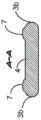
FIG. 1A is a cross-sectional view of the handle of FIG. 1;
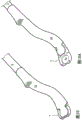
FIG. 2 is a schematic perspective view of an embodiment of a radiation treatment apparatus depicting a radiation source holder integrally connected to a treatment wand, wherein both are configured to function as an integral light guide according to an embodiment;
FIG. 2A is a schematic perspective view of a modified embodiment of the device depicted in FIG. 2, wherein the treatment rod is bifurcated into two rod branches of FIG. 1;
FIG. 2B is a schematic perspective view of another embodiment of the device depicted in FIG. 1, wherein a fixture according to an embodiment is non-integrally attached to a rod used as a plurality of light pipes;
FIG. 3 is a schematic perspective view of an embodiment of a radiation therapy device in which a fastener according to an embodiment is point-connected to a distal portion of each of two rod branches;
FIGS. 3B-3C are schematic cross-sectional views taken along section lines A-A, B-B and C-C, respectively, depicted in FIGS. 3-3A;
FIG. 4 is a schematic perspective view of a modified embodiment of the apparatus depicted in FIGS. 3-3D, wherein a fastener according to an embodiment is removably attached to one of the rod branches;
FIG. 4A is a schematic perspective view of the treatment rod depicted in FIG. 4 disassembled from the fasteners according to one embodiment;
FIG. 4B is a schematic perspective view of the fastener depicted in FIG. 4 disassembled from the rod according to one embodiment;
FIG. 4C is a schematic cross-sectional view of the device depicted in FIG. 4 along section line A-A according to an embodiment;
FIG. 5 is a schematic front view of a removably attached fastener having a notched connection configuration in accordance with an embodiment;
FIG. 5A is a schematic front view of a removably attachable therapeutic rod having a plurality of rod branches (fingers) corresponding to the notched connection configuration of the fastener depicted in FIG. 5, according to one embodiment;
FIG. 5B is a schematic front view of a removably attached treatment wand with the fixture depicted in FIG. 5 and the wand depicted in FIG. 5A in a connected state, according to one embodiment;
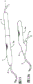
FIGS. 5C and 5D are schematic elevational views of a modified embodiment of the device depicted in FIG. 5B having an alternative branched configuration in accordance with an embodiment;
FIG. 6 is a schematic perspective view of a unitary prismatic face molded into a rod branch according to an embodiment;
FIG. 6A is a schematic perspective view of a rod branch having both an integral prismatic light redirecting surface and a focusing lens according to an embodiment;
FIG. 6B is a schematic perspective view of a modified embodiment of the rod branch of FIG. 6A having an opaque film selectively disposed on the surface to minimize undesired light emission through the rod, according to an embodiment;
FIG. 7 is a schematic elevational view of an alternative embodiment of a rod and mount arrangement, wherein the rod is used as a plurality of rigid hollow tubes configured to receive optical fibers or electrical wires when the illumination port is used as a light emitting diode according to an embodiment;
FIG. 8 is a schematic perspective view of an ophthalmic radiation device disposed in a treatment position behind an eyeball, wherein an illumination port surrounding a fixation member is visible through the pupil according to one embodiment;
FIG. 8A is a schematic perspective view of an ophthalmic radiation device disposed in a treatment position behind an eyeball with a radiation source adjacent the macula in accordance with one embodiment;
FIG. 9 is a schematic perspective view of a radioactive source material holder having an eye-ward facing holding cavity according to one embodiment;
FIG. 9A is a schematic cross-sectional view of the anchor depicted in FIG. 9 along section line A-A in accordance with an embodiment;
FIG. 9B is a schematic cross-sectional view along section line A-A of a variant embodiment of the fixture of FIG. 9, wherein the fixture chamber according to an embodiment is closed with a lid;
FIG. 9C is a schematic perspective view of a radioactive source material holder having a fixation lumen facing toward a cranium frame, according to one embodiment;
FIG. 9D is a schematic cross-sectional view of the anchor depicted in FIG. 9C along section line B-B in accordance with an embodiment;
FIG. 9D is a schematic cross-sectional view along section line B-B of a variant embodiment of the fixture of FIG. 9, wherein the fixture chamber is closed with a lid according to an embodiment;
figures 10 and 10A are schematic perspective views of an ophthalmic radiation device fitted with a radiation shielding sleeve in a tamper-evident state and a non-tamper-evident state, respectively, according to an embodiment;
FIG. 11 is a schematic perspective view of an ophthalmic radiation device configured to receive a radiation source in the lumen of an empty wand in accordance with one embodiment;
FIG. 11A is a schematic perspective view of a lumen along section line D-D according to an embodiment;
FIG. 11B is a schematic cross-sectional view of a lumen along section line E-E depicting a lumen limiter according to an embodiment;
FIG. 12 is a schematic perspective view of an ophthalmic radiation device having a tortuous fixture configured to receive a liquid therapeutic radioisotope in accordance with one embodiment;
FIG. 12A is a schematic perspective view of the ophthalmic radiation device depicted in FIG. 12 with a liquid therapeutic radioisotope disposed in a tortuous fixture in accordance with one embodiment;
fig. 12B is a schematic side view of a double-sided piston pump configured to simultaneously inject liquid radioisotopes and withdraw inert liquid from the tortuous fixture depicted in fig. 12 and 12A, in accordance with one embodiment;
FIG. 13 is a schematic perspective view of an ophthalmic radiation device in which light from an external light source is directed toward the device according to one embodiment;
FIG. 13A is a schematic perspective view of an ophthalmic radiation device in which light is directed into a handle proximate to a handle grip at a non-parallel angle to a longitudinal axis of the handle according to one embodiment;
FIG. 13B is a schematic perspective view of an ophthalmic radiation device with a light source disposed therein and powered by an external power source according to one embodiment; and
fig. 13C is a schematic perspective view of an ophthalmic radiation device in which light and a power source are themselves included in the device according to an embodiment.
FIG. 14 is a flow chart describing a process for inserting an ophthalmic radiation device into its treatment position, according to one embodiment; and
FIG. 15 is a flow diagram describing a process for inserting radiation source material into an ophthalmic radiation device after the device has been placed in a treatment position, in accordance with one embodiment;
FIG. 15A is a flow chart describing a process for inserting a liquid radioisotope into an ophthalmic radiation device after placement at a treatment site in accordance with one embodiment; and
FIG. 15B is a flow chart describing a method for visually identifying the location of hidden radiation source material, in accordance with one embodiment;
FIG. 16 is a schematic perspective view of a tamper-evident support disposed at a treatment site on a patient's face according to one embodiment.
It will be appreciated that for clarity, elements illustrated in the figures have been drawn with some magnification. For example, the dimensions of some of the elements may be exaggerated relative to other elements for clarity. Further, where considered appropriate, reference numerals may be repeated among the figures to indicate corresponding and analogous elements.
Detailed description of the invention
In the following detailed description, numerous specific details are set forth in order to provide a thorough understanding of the present invention. However, it will be understood by those skilled in the art that the present invention may be practiced without these specific details and that known methods, procedures, and components have not been described in detail so as not to obscure the invention.
Embodiments of the present invention generally relate to an ophthalmic radiation device and treatment method that facilitates placement of a therapeutic radioisotope on or near the eyeball and within its socket as indicated above. In particular, embodiments relate to efficiently directing light from a light source through the body of the wand to an illumination port by using the wand body itself as a light guide. The illumination port serves as a reference point for use by the practitioner to facilitate placement of the device at the correct treatment location.
The following terms are used throughout the literature:
"radiation source material," "source material," or "radiation source" all refer to radioactive material that provides a therapeutic dose of radiation. Non-limiting examples of radioisotopes include, inter alia, yttrium and strontium.
"holder" refers to a structure for holding or containing a therapeutic quantity of radioactive source material. The fixture may be configured to include the source material in either solid or liquid form, as will be discussed further.
"wand," "treatment wand," "wand body," or "wand body" refer to an elongated ergonomic structure that extends from a handle and supports a fastener at its distal end according to an embodiment. The rod is contoured to provide the surgeon with optimal access, visibility, control, and ergonomics for preventing fatigue. The wand is light transmissive and has minimal surface features to minimize dissipation of light through the body of the wand.
"agent" refers to a therapeutic agent, such as, inter alia, a drug or chemical, visible light, invisible electromagnetic radiation, or particulate radiation.
"practitioner" refers to a surgeon, doctor, nurse, or any other person who uses or assists in using radiation therapy.
"distal" and "proximal" are relative positional terms that are measured from the positional relationship of the end of the handle closest to the user holding the device. Thus, "distal end" refers to the point or portion furthest from the end of the user's handle closest to the grip handle, while "proximal end" refers to the point or portion closest to the end of the user's handle closest to the grip handle.
"distal portion" refers to a location proximal to the distal tip, but does not necessarily include the most distal point.
"light guide" refers to a substantially transparent solid body through which the propagation of light is directed according to the surface geometry of the body. "light pipe" refers to a particular type of light guide that functions as a fiber. "illumination source light pipe" refers to an optical fiber.
"opaque" refers to a state that is not transparent or transparent to light.
"grasping element" refers to a structure that secures the radioactive source material in a single position within the lumen of the rod. Thus, the wall protrusion limiting the cross-sectional area of the lumen is also considered a grasping element.
"surround" refers to surround, even if the source is non-circular.
According to one embodiment, in addition to administering therapeutic doses of radiation in the treatment of age-related macular degeneration (AMD), melanoma, and other types of eye diseases that respond to radiation, the device may also be used to administer drugs or therapeutic substances released from the body of the device into, through, or onto the sclera or other associated tissue, or to attach specialized pharmaceutical agents to the sclera itself.
Turning now to the drawings, FIG. 1 depicts an ophthalmic radiation device, generally designated 1, which enables a practitioner to apply a therapeutic dose of radiation to a target tissue. In a non-limiting embodiment, the device 1 includes a radioactive source material holder 4, a handle 2, a light pipe in communication with the light pipe 6, a coupling 5 for connecting the light pipe 6 to the handle 5, and a treatment rod 3 for inserting radioactive source material adjacent to target tissue.
The rod 3 may be made of a rigid substantially light transmissive polymeric material such as polycarbonate or polysulfone or other material that provides mechanical integrity and transparency to enable light to pass through the rod 3. In certain embodiments, the wand 3 is removably attached to the handle 2, while in other embodiments, the wand is permanently attached to the handle 2.
As shown in fig. 1A, according to an embodiment, the rod 3 extends into the body of the handle 2 and abuts an illumination source 6 fixed inside the handle 2 by means of a coupling 5, so that light can propagate from the illumination source 6 through the rod 3 to the distal end of the rod 3 close to the fixation member 4. It should be appreciated that in some embodiments, a non-contiguous connection configuration between the illumination source 6 and the rod 3 may be used.
Fig. 2-2C depict different rod embodiments, according to some embodiments, light passing through the rod is directed from an illumination source to a series of illumination ports 7, the illumination ports 7 surrounding a radiation source disposed in the fixture 4. The emitted beam advantageously provides a visual reference for identifying the position of the radioactive source material disposed in the fixture 4.
In particular, fig. 2 depicts a rod 3 integrally connected to a fixture 4 to enable light to pass through an illumination port 7 and also a fixture base 4c, a fixture wall 4a, or both, according to an embodiment. It will be appreciated that in these embodiments, both the mount 4 and the rod 3 are made of similar or identical light transmissive materials.
Fig. 2A depicts a variant embodiment of the rod depicted in fig. 2, in which the rod 3 is bifurcated into two branches 3a and 3b, said branches 3a and 3b being integrally connected to the fixture 4 to enable light to pass through the illumination port 7 and also the fixture base 4c and the fixture wall 4a, as previously described. In some embodiments, the fixture 4 is configured to block light from passing through any portion of the fixture and to cause substantially all of the emission of light to occur at the illumination port 7.
Fig. 2B depicts another variant embodiment of the wand and fixture depicted in fig. 2, in which the wand 3 is used as four separate light pipes 3c, said light pipes 3c propagating separate light through each light pipe 3c to an illumination port 7 provided in the fixture 4. It should be understood that any plurality of light pipes 3c are included within the scope of the present invention.
In some embodiments, illumination of each light pipe 3c is achieved by light of a different wavelength, while in other embodiments, the light pipes 3c are not illuminated at the same time.
It should also be understood that different combinations of illumination wavelength and timing are included within the scope of the present invention.
Fig. 3-3D depict a third variant embodiment having the above-described furcation bars permanently attached at only the distal and proximal portions 3D of the fastener 4 to minimize dissipation of light during propagation through the bar 4 and fastener 4. This structure is most clearly depicted in the cross-sectional views along section lines a-A, B-B and C-C depicted in fig. 3B-3D, respectively.
In particular, along section line a-a the rod branches 3a and 3B are permanently attached to the fixture 4, whereas along section line B-B the rod branches 3a and 3B are detached from the fixture, and along section line C-C each of the rod branches 3a and 3B is connected to the proximal portion of the fixture 4 via a mesh connection 3 k. The reduced thickness of the web attachment members 3k advantageously reduces the light dissipation in the fixture 4.
It will be appreciated that in some embodiments, the rods 3 may have opaque components or opaque surface layers or films applied to the surface to minimize light dissipation.
Fig. 4-4B depict an embodiment of a bifurcated rod removably attached to a fixture 4 in accordance with a particular embodiment. The connection is obtained by two sets of cooperating bent projections 8, each set being provided on a corresponding side of the fixing element 4.
Fig. 4C depicts a section along section line a-a and depicts rod branches 3a and 3b sandwiched between the flex protuberances 8.
According to an embodiment, this connector configuration also reduces light dissipation by the structure connected to the rod branches 3a and 3b, thereby maintaining the available light intensity of the illumination port 7.
Figures 5-5D illustrate an additional embodiment of a removably attachable connector for the wand 3 and the fixing 4. In particular, as shown in fig. 5A and 5C, the rod 3 branches into several rod fingers 9, said rod fingers 9 being configured as corresponding notches 11 sheared into the fixing elements of fig. 5 and 5D, respectively.
In some embodiments, the bar fingers 9 are used with a non-circular cross-section, with an illumination port provided at each distal end 12.
As shown, light rays 10 are directed along the length of the wand 3 and internally reflect off of the wand fingers 9 until they exit the illumination port 12 at the distal end of each of the wand fingers 9.
It is to be understood that any feature disclosed in the context of a particular embodiment may be applied to other embodiments.
Fig. 6 and 6A depict non-limiting embodiments having integral light directing structures for directing light to propagate through the rod branches. The light ray 14 schematically depicts the general direction of propagation through the light guide.
In particular, FIG. 6A depicts an embodiment of a rod branch 9 having an illumination or emission point 12 at the distal end of the branch 9. According to an embodiment, the reflecting surfaces 13 are used integrally in the branch body 9, so that each reflecting surface 13 forms an angle of substantially 45 ° with respect to the propagation axis of the incident light. As shown, according to an embodiment, the propagation of the light is redirected at an angle of about 90 ° to its incident propagation direction, thereby minimizing the dissipation of the light before exiting the branch body 9 at the distal end 12.
FIG. 6A depicts a non-limiting embodiment of the rod branch 3a depicted in FIG. 3. According to this embodiment, the illumination port 7 is arranged in the rod branch 3a directly opposite the reflective surface 13 to redirect the propagation direction through the illumination spot 7.
For embodiments in which the reflective surface 13 is offset by an angle of 45 ° relative to the propagation axis of the incident light, the illumination port is therefore displaced from a position directly relative to the reflective surface 13 to ensure that the redirected light passes through the illumination port 7.
In one non-limiting embodiment, each illumination spot 7 is used as an integrally connected focusing lens with a generally convex surface geometry having a radius of curvature that focuses light 14 on or near the retina when the device is inserted behind the eyeball.
In some embodiments, the central axis 19 of each lens or illumination port is oriented substantially perpendicular to the sclera to minimize the propagation path to the retina, thereby minimizing the dissipation of light through the sclera and retina and maximizing the intensity of the light.
However, it should be understood that embodiments are also within the scope of the present invention in which the central axis of the respective lens is not disposed at a substantially right angle relative to the sclera.
The protruding convex surface geometry provides certain physiological benefits by advantageously minimizing irritation when the illumination port 7 contacts the sclera during treatment and enhances illumination by coupling light transmittance.
In other non-limiting embodiments, the illumination port 7 is used in a geometry of flat or concave surface, the radius of curvature of which substantially corresponds to the curvature of the eyeball.
FIG. 6B depicts a variant embodiment of the branching rod of FIG. 6A having an opaque film 3h on selected surfaces of the rod body 3m to reduce or eliminate light emitted from the rod body 3m and allow emission from the illumination port 7. This configuration advantageously causes the illumination ports 7 to be visually highlighted to facilitate identification of the radioactive source material relative to the illumination ports 7.
The opaque film may be applied by dipping the rod into a material such as urethane and then removing the resulting film from the designated illumination port. Advantageously, the desired opaque film may be formed on the rod surface by two-shot molding as known to those skilled in the art. It should be noted that the terms "coating" and "film" are used interchangeably in this document.
Fig. 7 depicts an alternative embodiment in which the rod 3 is used as a plurality of empty branches 3 e. In some embodiments, concentric optical fibers are disposed in each branch in the fixture 4 at their distal ends, forming illumination ports 7. In other embodiments, the lumen of each rod branch 3e includes wires for a micro Light Emitting Diode (LED) or other light generating electrical device disposed in the fixture 4 to generate a light beam emitted from the illumination port 7.
It should be appreciated that in some embodiments, a single device may use any combination of illumination devices, such as LEDs, optical fibers, light pipes, or integral light guides, to create an illumination point or illumination port. Moreover, it should be understood that in some embodiments, the rod 3 may comprise two or more illumination points, which are arranged equidistantly on opposite sides of the fixture wall itself or adjacent to said wall in other non-limiting embodiments.
Fig. 8 and 8A are a schematic view, a perspective view, and a side sectional view, respectively, depicting a rod 3 disposed behind an eyeball 17 adjacent to an optic nerve 17a to administer a therapeutic dose of radiation from a radioactive material 4f included in a fixation member 4 to the macula 17 b.
As noted above, in certain embodiments, the rod branches 3a and 3b include an illumination port 7 having a convex focusing lens configured to focus light on or near the retina. This lens orientation may be achieved primarily by the overall concavity of the rod branches 3a and 3b substantially conforming to the contour of the eye 7.
The illumination port 7 can be seen along a line of sight 19a by transpupillary ophthalmoscopy.
As best shown in fig. 8A, according to one embodiment, the fixture 4 is used as a disk having a distal concave surface or notch 20 to receive the optical fiber 18 when the rod is disposed in the treatment position. This configuration provides further guidance to the practitioner in positioning the anchor 4 to the appropriate treatment location by providing tactile feedback after the anchor 4 and optic nerve 17a are abutted.
A non-limiting example of such a recess is one having a radius of curvature of about 2.5mm to 3 mm. Moreover, the recess 20 advantageously allows the radioactive source material 4f to be placed closest to the macula for optimal treatment.
It should be understood that notches or slots of various geometries that meet the needs and anatomical requirements of a single patient are also included within the scope of the present invention.
In some embodiments, rather than using distal notches 20, anchors 4 are used with rounded distal ends, such as for treating intraocular tumors.
In some embodiments, visual support may be further increased by attaching a subminiature camera and light emitting element (e.g., fiber optics or LEDs) to the distal end of the fixture 4. This configuration advantageously allows the surgeon to view directly and avoid obstructing the rod's path during insertion and placement against the optic nerve sheath 17 a.
As noted above, the portion of the rod 3 configured for insertion behind the eyeball 17 in the cranium has acceptable ergonomics to minimize patient trauma and surgeon fatigue. In particular, the insertion portion has a rounded profile, an overall curvature substantially corresponding to the curvature of the eyeball and is thin; in one non-limiting embodiment, the maximum thickness at the narrowest point is less than about 5.0mm, and the width is in the range of about 10.0mm to about 6 mm.
In particular, figures 9 and 9C respectively describe a non-limiting embodiment of a fixation member 4, said fixation member 4 having a fixation cavity 4b facing towards the eyeball or towards the skull rim when the stick is placed in the treatment position.
Fig. 9A and 9B are cross-sectional views along section line a-a and depict two variant embodiments of the embodiment of fig. 9.
As shown in fig. 9A, the fixing cavity 4b is defined by a fixing base 4c and a fixing wall 4 a. According to a particular embodiment, the dimensions of diameter and depth are defined according to the required dimensions of the radioactive source material to be disposed in the fixture cavity 4b during treatment. In this uncapped embodiment, the radioactive source material is attached to the fixture base 4 c.
Figure 9B depicts a generally similar embodiment of figure 9A with the addition of a holder cover 4e to completely enclose the radioactive source material disposed in the holder cavity 4B. In some embodiments, the sealed holder configuration advantageously allows the radioactive source material to be used as a solid, powder, or even as a liquid.
The fixture cover or lid 4e may be attached to the fixture wall 4a by glue, ultrasonic welding or mechanical means, such as threads or a crimped projection, among others.
In some embodiments, the fixture 4 and the fixture cover 4e are made of a polymeric material, such as polycarbonate or polysulfone or even a metallic material. The fastener cover 4e may have a relative thickness ranging from 0.1mm to 1mm according to a certain non-limiting embodiment.
As noted above, fig. 9C and related cross-sectional views, fig. 9C and 9D generally depict a generally similar embodiment, except for the direction of the fastener lumen opening. In these embodiments, the fastener wall 4a and base 4c define a fastener cavity 4B that opens toward the skull rim, and are otherwise similar to the embodiment described in fig. 9A and 9B.
According to one non-limiting embodiment, the fastener base 4c is used as a relatively thin polymeric material, such as polycarbonate or polysulfone, with a minimum thickness in the range of from 0.2mm to 1mm, so that radiation can effectively pass through the fastener base 4c into the target tissue.
It should be appreciated that the anchor lumen may be used in a variety of shapes depending on the desired shape of the radioactive source material.
Fig. 10A-10B depict a radiation-shielding sleeve 22 according to one embodiment, the sleeve 22 being slidably mounted on the wand 3 so that a user can slide the sleeve in and out of the tamper-evident mode along the wand 3. This function advantageously protects the practitioner and patient from radiation during insertion and removal of the radiation device if such protection is deemed necessary.
In particular, fig. 10 and 10A depict the tamper evident sleeve 22 disposed in a tamper evident mode and a non-tamper evident mode, respectively. When set in the tamperproof mode, the sleeve 22 covers the radioactive source material 4f disposed in the holder 4, and when slid up the wand 3 into the non-tamperproof mode, the radioactive source 4a is exposed for treatment.
It should be noted that, according to a non-limiting embodiment, the tamper evident sleeve 22 is typically made of a tamper evident material such as a high molecular polymer with additives or other materials that exhibit similar functions.
Generally, the distal region of the tamper evident sleeve 22 should be as thin as possible to facilitate sliding of the sleeve 22 while the wand 3 is disposed at the treatment site both before and after administration of the radiation therapy. It will be appreciated that in some embodiments, the tamper evident sleeve remains stationary while the rod and securing member 4 slide in and out of the treatment site.
Figure 11 depicts a rod embodiment configured to facilitate insertion of the radiation source material 4f into the distal end of the rod 3 after it is disposed in the treatment position. As shown, according to one embodiment, the rod 3 is used as a relatively flat, hollow tube having an inner lumen 3f (best seen in fig. 11A and 11B) through which the source material 4f in solid form advances when pushed by the semi-flexible insert 23.
FIGS. 11A and 11B are cross-sectional views depicting lumen geometry of the lumen cross-section at section lines D-D and E-E, respectively. As shown in FIG. 11A, the cross-sectional area of the lumen is sufficient for the passage of source material 4f, while at the distal end of rod 3, at section line E-E, the cross-sectional area 3f is limited by wall bulge 3 j. The lumen limiter engages the source material 4f between the lumen walls at the distal end of the rod 3, securing it in the treatment position. It should be understood that lumen wall bulges or other means of securing the source material 4f in the treatment position within the lumen 3f are included within the scope of the present invention.
Fig. 12-12A depict an alternative embodiment of the wand depicted in fig. 11in which the liquid radioisotope is ejected into a passage leading to a reservoir or tortuous network disposed in the distal portion of the wand 3. It should be understood that liquid radioisotopes include, inter alia, suspensions of different types of specific radioisotopes in a carrier liquid. Examples of carriers include glycerol and water, among others.
Examples of specific radioisotopes include, inter alia, neutron activated glass microspheres such as yttrium aluminosilicate, magnesium aluminosilicate, holmium-166, erbium-169, dysprosium-165, rhenium-186, rhenium-188, yttrium-90, or other elements on the periodic table.
In certain embodiments, certain radioisotopes are used as non-radioactive glasses mixed with radioactive materials, such as iodine-125, palladium-103, and strontium-90, among others, to emit low-energy gamma rays.
In another embodiment, the specific radioisotope is selected from Auger emitters such as, inter alia, 67Ga, 99mTc, 111In, 123I, 125I and 201Tl or from Alpha emitters such as, inter alia, uranium, thorium, radium, actinium and other transuranic elements.
In other embodiments, the particular radioisotope is especially useful as89Sr、90Sr,169Yb、32P、33P、90Y、192Ir、25I、131I、103Pd、177Lu、149Pm、140La、153Sm、186Re、188Re、166Ho、166Dy、137Cs、57Co、169Er,
165Dy、97Ru、193mPt、195mPt、105Rh、68Ni、67Cu、64Cu、109Cd、11Ag,
198Au、199Au、201Tl、175Yb、47Sc、159Gd、212Bi、and77Any one or combination of As.
As shown in fig. 12, a tortuous network 26 is provided at the distal end of the wand 3 in fluid communication with the pump 28 of fig. 12B via the channels 25 and 24. In certain embodiments, the entire liquid delivery system, i.e., pump 28, tortuous network 26 and passages 25 and 24, are used as a closed system comprising two different liquids, inert fluid 30 and liquid radioisotope 4 g.
As shown only in fig. 12, according to one embodiment, the inert fluid is initially placed in the tortuous network 26 and passages 25 and 24, while the liquid radioisotope 29 is placed in a stationary chamber 32 connected to a pump 28. When starting the treatment, the liquid radioisotope 29 is ejected into the channel 25, shown as the source material supply line, and displaces the inert liquid 30 provided in the tortuous network 26 supplied into the second stationary chamber 31.
According to some embodiments, when the treatment is completed, the double-sided piston 33 is driven in the reverse direction to expel the inert liquid 30 from the second stationary chamber 31 and eject it through the channel 24 into the tortuous network 26, where the liquid radioisotope 29 is displaced and returned to the stationary chamber 33 until the next treatment.
The tortuous network 26 advantageously maximizes the amount of liquid isotope 4f to which the target tissue may be exposed. In certain embodiments, a pump 28 is disposed at the proximal end of the wand 3. A non-limiting example of a liquid radioisotope is a suspension of ytterbium, examples of suitable inert liquids include water and glycerol, among others.
Fig. 13-13D all depict a lightweight handle 2 that provides fully comfortable rod control during insertion, removal, and administration of therapeutic radiation. With respect to the illumination source, fig. 13-13C depict various embodiments of the illumination source or light sources.
In particular, fig. 13 depicts a non-limiting handle embodiment in which illumination from an external light source (not shown) is piped into the handle 2 through a light pipe 6 and coupling 5 disposed at the proximal end of the handle 2.
Fig. 13A depicts a non-limiting handle embodiment in which illumination from an external light source (not shown) is coupled against the handle grip at an angle non-parallel to the longitudinal axis of the handle 2 to advantageously reduce torque.
Fig. 13B depicts a non-limiting handle embodiment in which illumination is provided by an internal light source disposed inside the illumination housing 5a and powered by an external power source (not shown) via cable 6 a.
Fig. 13C depicts a non-limiting handle embodiment in which illumination is provided by an internal light and power source disposed within the illumination housing 5 a.
It should be appreciated that light control features may also be provided for controlling brightness, color and time responsive audio and visual feedback mechanisms configured to alert medical personnel as needed. This function may be provided with associated hardware embedded in the handle 2, as known to those skilled in the art, according to an embodiment, or built in a cradle communicating with the handle according to another embodiment.
It should further be appreciated that in some embodiments, the color or frequency of the emitted light at the respective illumination port may be different from the emitted light at other illumination ports, and the frequency of light emission at each illumination port may be independently variably controlled.
FIG. 14 depicts a method for facilitating placement of radiation source material at a treatment location using a visual reference point generated by an illumination port proximate to the radiation source material, in accordance with one embodiment.
Specifically, in step 35, an ophthalmic radiation device including a treatment rod having the above-described light emitting configuration is provided. In step 36, light propagates through the wand from an illumination source in the handle to the illumination port. In step 37, the practitioner placing the device at the treatment site orients the radiation source fixture according to the reference points created by the illumination ports. In step 38, the physician performs additional guidance based on the tactile feedback generated by the contact of the distal end of the anchor with the optic nerve. In step 39, the radiation-shielding sleeve is slid toward the handle to uncover and expose the radioactive source material in the holder for administration of the therapeutic radiation. In step 40, the device is removed from the treatment site after the source material is covered by the tamper evident device.
Figures 15 and 15A are flow charts depicting treatment steps of an apparatus configured to receive radiation source material after placement in a treatment position.
Specifically, in step 41 of FIG. 15, referring to FIGS. 11-11B, an embodiment of a radiation device having a rod lumen is provided. In step 42, the rod 3 is placed in the treatment position. In step 43, the radioactive source material 4f is pushed through the lumen 3f into its treatment position at the distal point of the rod lumen. In step 44, the source material is embedded in place by the grasping elements 3j bounding the lumen 3 f.
In fig. 15A, and with reference to fig. 12-12B, an embodiment of a radiation device including a serpentine network 26 is provided. In step 46, the wand is inserted into the treatment position. In step 47, the liquid radioisotope is injected through the passages 25 and 24 into the tortuous network 26. In step 48, the inert liquid injected into the tortuous network 26 displaces the liquid radioisotope back into its dedicated storage chamber.
In the next use, according to one embodiment, the liquid radioisotope 4g is obtained from the fixed chamber and injected into the tortuous network 26 and the inert liquid 30 is displaced into the dedicated storage chamber. It should be noted that injection is achieved by a slave piston as described above.
FIG. 15B is a flow diagram of a method for facilitating visual identification of the location of concealed radiation source material based on a visually identifiable reference according to an embodiment of a radiation device.
It should be appreciated that the method can be applied in a variety of situations where the source material is hidden and the beam provides a visually identifiable reference.
Specifically, in step 51, a hidden radioactive source material disposed in a fixture is provided.
In step 52, light propagates through the substantially optically transparent rod.
In step 53, a beam of light emitted from light propagating through the substantially light-transmitting rod is emitted from each of a series of illumination ports at least partially surrounding a hidden radioactive source material in the fixture.
Fig. 16 is a schematic perspective view of a tamper-evident support, generally designated 60, disposed in a treatment position on a patient's face 62 for minimizing exposure to radiation by the patient and practitioner and providing stability to the device during treatment.
The tamper-evident support is made of, for example, a high molecular polymer, and in some embodiments has a semi-flexible bottom surface configured to substantially conform to the contours of the patient's face 62. The support member 63 is traversed by an aperture 61, the aperture 61 being configured to receive a handle of an ophthalmic radiation device and provide a primary direction of insertion of the device into a treatment site.
According to one embodiment, the cradle is positioned on the patient's face during treatment, and the rod is inserted into the bore 61 and supported in part by the support member 63 while the practitioner maintains the rod in the treatment position.
It should be noted that stent embodiments lacking radiological tamper resistance are also included within the scope of the present invention.
It should be further appreciated that in some embodiments, the color or frequency of the emitted light of the respective illumination port may be different from the emitted light of the other illumination ports, and the frequency of light emission at each illumination port may be independently variably controlled.
It should also be understood that different combinations of features disclosed in different embodiments are included within the scope of the invention.
While certain features of the invention have been illustrated and described herein, many modifications, substitutions, changes, and equivalents will now occur to those skilled in the art. It is, therefore, to be understood that the appended claims are intended to cover all such modifications and changes as fall within the true spirit of the invention.
Claims (7)
1. An ophthalmic treatment wand comprising:
an elongated body made of light transmissive material, the elongated body having a proximal end and a distal end and being configured to receive a radioactive source material holder at the distal end;
a series of illumination ports at the distal end, the illumination ports arranged to at least partially enclose a radioactive source material holder received at the distal end;
wherein light propagating from the proximal end through the optically transmissive material of the elongate body itself toward the distal end is emitted from the illumination port;
each of the illumination ports includes a convex geometry projecting outwardly from a surface of the rod to provide a contact point with a sclera of an eye and configured to direct light substantially near a retina when the rod is disposed in a treatment position, each of the illumination ports having a central axis disposed substantially perpendicular to the sclera when the rod is disposed in the treatment position, each of the illumination ports directing light received from the rod through a length thereof made of a light transmissive material.
2. An ophthalmic radiation device for delivering a therapeutic dose of radiation to diseased ocular tissue, the device comprising:
a radioactive source material holder; and
the ophthalmic treatment wand of claim 1.
3. The device of claim 2, wherein the fixture includes a recess disposed in a distal edge of the fixture to receive an optic nerve when the device is in a treatment position.
4. The apparatus of claim 2, wherein the fixture includes one or more connection formations operable to provide removable attachment to the wand.
5. The device of claim 2, wherein the fixture is integrally attached to the rod.
6. The device of claim 2, wherein the fixture comprises an opaque film that selectively covers a surface of the rod.
7. The apparatus of claim 2, further comprising a radiation-shielding sleeve slidably mounted to the wand.
Applications Claiming Priority (3)
| Application Number | Priority Date | Filing Date | Title |
|---|---|---|---|
| US201261723654P | 2012-11-07 | 2012-11-07 | |
| US61/723,654 | 2012-11-07 | ||
| PCT/US2013/068944 WO2014074712A2 (en) | 2012-11-07 | 2013-11-07 | Light-guided ophthalmic radiation device |
Publications (2)
| Publication Number | Publication Date |
|---|---|
| CN104994814A CN104994814A (en) | 2015-10-21 |
| CN104994814B true CN104994814B (en) | 2020-03-24 |
Family
ID=50685313
Family Applications (1)
| Application Number | Title | Priority Date | Filing Date |
|---|---|---|---|
| CN201380064079.8A Active CN104994814B (en) | 2012-11-07 | 2013-11-07 | Light-guide ophthalmic radiation device |
Country Status (12)
| Country | Link |
|---|---|
| US (1) | US10173075B2 (en) |
| EP (1) | EP2916910B1 (en) |
| JP (1) | JP6300817B2 (en) |
| CN (1) | CN104994814B (en) |
| AU (1) | AU2013341157B2 (en) |
| CA (1) | CA2890847C (en) |
| ES (1) | ES2713199T3 (en) |
| HK (1) | HK1216295A1 (en) |
| IL (1) | IL238663B (en) |
| IN (1) | IN2015DN03888A (en) |
| PL (1) | PL2916910T3 (en) |
| WO (1) | WO2014074712A2 (en) |
Families Citing this family (16)
| Publication number | Priority date | Publication date | Assignee | Title |
|---|---|---|---|---|
| US10022558B1 (en) | 2008-01-07 | 2018-07-17 | Salutaris Medical Devices, Inc. | Methods and devices for minimally-invasive delivery of radiation to the eye |
| WO2017112891A1 (en) * | 2015-12-22 | 2017-06-29 | Salutaris Medical Devices, Inc. | Brachytherapy applicator systems and methods |
| US9873001B2 (en) | 2008-01-07 | 2018-01-23 | Salutaris Medical Devices, Inc. | Methods and devices for minimally-invasive delivery of radiation to the eye |
| EP3013290B1 (en) * | 2013-06-25 | 2017-09-27 | Teclens, LLC | Apparatus for phototherapy of the eye |
| US10117578B2 (en) | 2013-12-31 | 2018-11-06 | Ip Liberty Vision Corporation | Luminescent ophthalmic device |
| US10166143B2 (en) * | 2013-12-31 | 2019-01-01 | Ip Liberty Vision Corporation | Versatile light-guided ophthalmic treatment system |
| USD815285S1 (en) | 2016-05-11 | 2018-04-10 | Salutaris Medical Devices, Inc. | Brachytherapy device |
| USD814637S1 (en) | 2016-05-11 | 2018-04-03 | Salutaris Medical Devices, Inc. | Brachytherapy device |
| USD814638S1 (en) | 2016-05-11 | 2018-04-03 | Salutaris Medical Devices, Inc. | Brachytherapy device |
| USD808529S1 (en) | 2016-08-31 | 2018-01-23 | Salutaris Medical Devices, Inc. | Holder for a brachytherapy device |
| USD808528S1 (en) | 2016-08-31 | 2018-01-23 | Salutaris Medical Devices, Inc. | Holder for a brachytherapy device |
| GB201714392D0 (en) | 2017-09-07 | 2017-10-25 | Marsteller Laurence | Methods and devices for treating glaucoma |
| WO2021035069A1 (en) * | 2019-08-20 | 2021-02-25 | Radiance Therapeutics, Inc. | Single-use brachytherapy systems |
| CN112770703A (en) | 2018-09-28 | 2021-05-07 | 光辉疗法公司 | Methods, systems, and compositions for maintaining a functional drainage bubble associated with a minimally invasive microsclerostomia |
| EP3886777A4 (en) | 2018-11-29 | 2022-08-10 | Radiance Therapeutics, Inc. | Ophthalmic brachytherapy systems and devices for application of beta radiation |
| US11730976B1 (en) | 2022-11-01 | 2023-08-22 | Ip Liberty Corporation | Applicator with a radiation source within a module for treating tissue having enhanced visualization and radiation shielding capabilities |
Family Cites Families (14)
| Publication number | Priority date | Publication date | Assignee | Title |
|---|---|---|---|---|
| US4545337A (en) * | 1981-12-14 | 1985-10-08 | Lyons George A | Rotary valve engine |
| CN2136646Y (en) * | 1992-03-16 | 1993-06-23 | 济南市中心医院 | Radiation keratotomy incision straight marking device |
| US5637073A (en) | 1995-08-28 | 1997-06-10 | Freire; Jorge E. | Radiation therapy for treating macular degeneration and applicator |
| US6270491B1 (en) | 1999-04-06 | 2001-08-07 | Duke University | Intensity controllable hand-held surgical light |
| WO2001028473A1 (en) | 1999-10-21 | 2001-04-26 | Alcon Universal Ltd. | Sub-tenon drug delivery |
| US6443881B1 (en) * | 2000-06-06 | 2002-09-03 | Paul T. Finger | Ophthalmic brachytherapy device |
| US7070554B2 (en) * | 2003-01-15 | 2006-07-04 | Theragenics Corporation | Brachytherapy devices and methods of using them |
| US6957907B2 (en) * | 2003-04-11 | 2005-10-25 | Ultradent Products, Inc. | Illumination apparatus having a light-converting lens for increasing visual contrast between different oral tissues |
| US20050049508A1 (en) * | 2003-08-06 | 2005-03-03 | Michael Forman | Treatment of age-related macular degeneration |
| US20070260231A1 (en) * | 2005-04-21 | 2007-11-08 | Ondine International, Ltd. | Optical probe for delivery of light |
| US8684577B2 (en) * | 2005-05-13 | 2014-04-01 | Invuity, Inc. | Body cavity illumination system |
| CA2608366A1 (en) | 2005-05-18 | 2006-11-23 | Surmodics, Inc. | Insertion instrument for non-linear medical devices |
| US7862496B2 (en) | 2005-11-10 | 2011-01-04 | Cianna Medical, Inc. | Brachytherapy apparatus and methods for using them |
| KR101691368B1 (en) | 2008-01-07 | 2016-12-30 | 살루타리스 메디컬 디바이스즈, 인코퍼레이티드 | Devices for minimally-invasive extraocular delivery of radiation to the posterior portion of the eye |
-
2013
- 2013-11-07 PL PL13853945T patent/PL2916910T3/en unknown
- 2013-11-07 ES ES13853945T patent/ES2713199T3/en active Active
- 2013-11-07 JP JP2015541892A patent/JP6300817B2/en active Active
- 2013-11-07 WO PCT/US2013/068944 patent/WO2014074712A2/en active Application Filing
- 2013-11-07 CA CA2890847A patent/CA2890847C/en active Active
- 2013-11-07 CN CN201380064079.8A patent/CN104994814B/en active Active
- 2013-11-07 AU AU2013341157A patent/AU2013341157B2/en active Active
- 2013-11-07 IN IN3888DEN2015 patent/IN2015DN03888A/en unknown
- 2013-11-07 US US14/440,881 patent/US10173075B2/en active Active
- 2013-11-07 EP EP13853945.7A patent/EP2916910B1/en active Active
-
2015
- 2015-05-06 IL IL238663A patent/IL238663B/en active IP Right Grant
-
2016
- 2016-04-15 HK HK16104325.0A patent/HK1216295A1/en unknown
Also Published As
| Publication number | Publication date |
|---|---|
| AU2013341157A1 (en) | 2015-05-28 |
| CA2890847A1 (en) | 2014-05-15 |
| WO2014074712A3 (en) | 2015-07-23 |
| PL2916910T3 (en) | 2019-06-28 |
| EP2916910A4 (en) | 2017-03-15 |
| IL238663A0 (en) | 2015-06-30 |
| CA2890847C (en) | 2019-07-16 |
| HK1216295A1 (en) | 2016-11-04 |
| EP2916910B1 (en) | 2019-01-02 |
| CN104994814A (en) | 2015-10-21 |
| EP2916910A2 (en) | 2015-09-16 |
| JP6300817B2 (en) | 2018-03-28 |
| WO2014074712A2 (en) | 2014-05-15 |
| US10173075B2 (en) | 2019-01-08 |
| AU2013341157B2 (en) | 2017-08-31 |
| IN2015DN03888A (en) | 2015-10-02 |
| ES2713199T3 (en) | 2019-05-20 |
| US20150265850A1 (en) | 2015-09-24 |
| JP2016501052A (en) | 2016-01-18 |
| IL238663B (en) | 2020-01-30 |
Similar Documents
| Publication | Publication Date | Title |
|---|---|---|
| CN104994814B (en) | Light-guide ophthalmic radiation device | |
| CN105451637B (en) | Wide visual field eye imaging devices and its correlation technique | |
| US8206426B2 (en) | Light source and fiber optic brush for light delivery | |
| EP3227880B1 (en) | Injection training tool emitting omnidirectional light | |
| US20080255549A1 (en) | Photodynamic therapy device | |
| BRPI0906416B1 (en) | fixed-shaped cannula | |
| AU2017216559B2 (en) | Sheathed optical fiber | |
| KR20100138922A (en) | Light delivery device that provides a radial light output pattern | |
| US20080172115A1 (en) | Fiber optic brush for light delivery | |
| US11045665B2 (en) | Light-guided ophthalmic radiation device | |
| US11730976B1 (en) | Applicator with a radiation source within a module for treating tissue having enhanced visualization and radiation shielding capabilities | |
| JP2016214373A (en) | Light irradiator system, uterine cervix photodynamic therapy device, and irradiation method | |
| US20130029286A1 (en) | Devices and methods for conforming photodynamic therapy to specific anatomic locations | |
| CN212347463U (en) | Accurate photodynamic therapy device fixes a position | |
| RU2435618C1 (en) | Mouth, tongue, throat, larynx and/or oesophagus phototherapy nozzle | |
| CN116568359A (en) | Light irradiation medical device | |
| from Beyond | Loupes from Evident Dental | |
| PL197108B1 (en) | Diffuser |
Legal Events
| Date | Code | Title | Description |
|---|---|---|---|
| C06 | Publication | ||
| PB01 | Publication | ||
| C10 | Entry into substantive examination | ||
| SE01 | Entry into force of request for substantive examination | ||
| REG | Reference to a national code |
Ref country code: HK Ref legal event code: DE Ref document number: 1216295 Country of ref document: HK |
|
| GR01 | Patent grant | ||
| GR01 | Patent grant | ||
| REG | Reference to a national code |
Ref country code: HK Ref legal event code: WD Ref document number: 1216295 Country of ref document: HK |