CN104936522B - Ceiling suspension system - Google Patents
Ceiling suspension system Download PDFInfo
- Publication number
- CN104936522B CN104936522B CN201480005005.1A CN201480005005A CN104936522B CN 104936522 B CN104936522 B CN 104936522B CN 201480005005 A CN201480005005 A CN 201480005005A CN 104936522 B CN104936522 B CN 104936522B
- Authority
- CN
- China
- Prior art keywords
- image acquisition
- support
- rail
- arrangement
- patient
- Prior art date
- Legal status (The legal status is an assumption and is not a legal conclusion. Google has not performed a legal analysis and makes no representation as to the accuracy of the status listed.)
- Expired - Fee Related
Links
- 239000000725 suspension Substances 0.000 title description 5
- 238000003384 imaging method Methods 0.000 claims abstract description 38
- 230000008901 benefit Effects 0.000 description 15
- 238000002059 diagnostic imaging Methods 0.000 description 11
- 238000000034 method Methods 0.000 description 5
- 230000005855 radiation Effects 0.000 description 5
- 230000036512 infertility Effects 0.000 description 4
- 238000002360 preparation method Methods 0.000 description 4
- 230000008859 change Effects 0.000 description 3
- 230000008878 coupling Effects 0.000 description 3
- 238000010168 coupling process Methods 0.000 description 3
- 238000005859 coupling reaction Methods 0.000 description 3
- 230000001419 dependent effect Effects 0.000 description 3
- 230000009286 beneficial effect Effects 0.000 description 2
- 238000004140 cleaning Methods 0.000 description 2
- 238000006073 displacement reaction Methods 0.000 description 2
- 230000000694 effects Effects 0.000 description 2
- 238000005516 engineering process Methods 0.000 description 2
- 238000009434 installation Methods 0.000 description 2
- 241000894006 Bacteria Species 0.000 description 1
- 229910000831 Steel Inorganic materials 0.000 description 1
- 238000010521 absorption reaction Methods 0.000 description 1
- XAGFODPZIPBFFR-UHFFFAOYSA-N aluminium Chemical compound [Al] XAGFODPZIPBFFR-UHFFFAOYSA-N 0.000 description 1
- 229910052782 aluminium Inorganic materials 0.000 description 1
- 230000000977 initiatory effect Effects 0.000 description 1
- 238000012423 maintenance Methods 0.000 description 1
- 239000000463 material Substances 0.000 description 1
- 230000007246 mechanism Effects 0.000 description 1
- 230000006641 stabilisation Effects 0.000 description 1
- 238000011105 stabilization Methods 0.000 description 1
- 230000000087 stabilizing effect Effects 0.000 description 1
- 239000010959 steel Substances 0.000 description 1
- 230000002195 synergetic effect Effects 0.000 description 1
Images


Classifications
-
- A—HUMAN NECESSITIES
- A61—MEDICAL OR VETERINARY SCIENCE; HYGIENE
- A61B—DIAGNOSIS; SURGERY; IDENTIFICATION
- A61B6/00—Apparatus for radiation diagnosis, e.g. combined with radiation therapy equipment
- A61B6/44—Constructional features of apparatus for radiation diagnosis
- A61B6/4429—Constructional features of apparatus for radiation diagnosis related to the mounting of source units and detector units
- A61B6/4435—Constructional features of apparatus for radiation diagnosis related to the mounting of source units and detector units the source unit and the detector unit being coupled by a rigid structure
- A61B6/4441—Constructional features of apparatus for radiation diagnosis related to the mounting of source units and detector units the source unit and the detector unit being coupled by a rigid structure the rigid structure being a C-arm or U-arm
-
- A—HUMAN NECESSITIES
- A61—MEDICAL OR VETERINARY SCIENCE; HYGIENE
- A61B—DIAGNOSIS; SURGERY; IDENTIFICATION
- A61B6/00—Apparatus for radiation diagnosis, e.g. combined with radiation therapy equipment
- A61B6/44—Constructional features of apparatus for radiation diagnosis
- A61B6/4429—Constructional features of apparatus for radiation diagnosis related to the mounting of source units and detector units
- A61B6/4464—Constructional features of apparatus for radiation diagnosis related to the mounting of source units and detector units the source unit or the detector unit being mounted to ceiling
-
- A—HUMAN NECESSITIES
- A61—MEDICAL OR VETERINARY SCIENCE; HYGIENE
- A61B—DIAGNOSIS; SURGERY; IDENTIFICATION
- A61B6/00—Apparatus for radiation diagnosis, e.g. combined with radiation therapy equipment
- A61B6/44—Constructional features of apparatus for radiation diagnosis
- A61B6/4423—Constructional features of apparatus for radiation diagnosis related to hygiene or sterilisation
Abstract
The invention relates to the acquisition of medical image information of an object. In order to improve the operating room and to allow a more efficient use of equipment and personnel during an intervention, a medical X-ray system (10) is provided, comprising a patient support (12), an X-ray image acquisition arrangement (14), a support arrangement (16) and a rail arrangement (18). An image acquisition device (14) acquires imaging information of an object of interest (20) arranged on a patient support (12). A rail device (18) is disposed above the head. The support device (16) is movably mounted to the rail device (18) and is movable at least along the rail device (18). An image acquisition device (14) is movably mounted to the support device (16) to allow image acquisition of the object (20) from different directions. A rail arrangement (18) is arranged transverse to the longitudinal direction of the patient support.
Description
Technical Field
The invention relates to the acquisition of medical image information of an object. In particular, the present invention relates to a medical X-ray imaging system for providing medical imaging information of an object.
Background
X-ray interventions become more and more complex, in particular due to the systems and devices required, as well as personnel and third party equipment. In particular, stationary X-ray systems are commonly used in operating rooms for performing minimally invasive or hybrid procedures. As methods and available technology develop, these operating rooms accommodate more and more equipment and medical personnel. For effective interventions, effective cooperation of the involved devices and personnel may become important. WO 2010/137116 a1 describes a security system for dynamic 3D healthcare environments and a medical examination system with motorized equipment.
Disclosure of Invention
Accordingly, there may be a need for an improved operating room in order to allow more efficient use of equipment and personnel during an intervention.
The object of the invention is solved by the subject matter of the independent claims, wherein further embodiments are incorporated in the dependent claims.
According to the present invention, a medical X-ray imaging system is provided, comprising a patient support, an X-ray image acquisition arrangement, a support arrangement and a rail arrangement. An image acquisition device acquires image information of an object arranged on a patient support. A rail arrangement is disposed above the head and a support arrangement is movably mounted to the rail arrangement. The support means is movable at least along the rail means. The image acquisition device is movably mounted to the support device to allow image acquisition of the object from different directions. In addition, the patient support has a longitudinal direction, and the rail arrangement extends in a longitudinal rail direction transverse to the longitudinal direction of the patient support.
The advantage of the laterally arranged guide rails can be seen in the possibility of moving the imaging system, in particular the X-ray image acquisition device, out of the active area, for example out of the space required for medical staff to stand and move. A laterally arranged rail arrangement is further advantageous if room areas on the lateral sides of the patient support are available. Due to the possibility of moving the image acquisition arrangement laterally with respect to the patient, off-center imaging is possible.
The rail arrangement may comprise a longitudinal extension, which may for example be within the length of the patient support. This allows achieving the necessary degree of movement of the image acquisition means and at least a part of the support means. For example, this laterally extending rail arrangement may extend from one side wall to the other opposite side wall to allow the image acquisition system to be moved completely out of the patient support area or completely out of the center of the operating room to park the image acquisition system in a side area of the room, for example. The possibility of moving the device out of the treatment area of the patient may be very important for the preparation or cleaning of the operating room and the preparation of the patient before and after the intervention. In addition, sterility and hygiene aspects may be better considered. In other words, the laterally arranged rail arrangement allows positioning the X-ray image acquisition arrangement around the patient for acquiring images, and provides an advantageous standby position when the device is not actively needed. In addition, a parking position may be possible in which the imaging device may be completely removed and moved out of the active area of the operating room.
In general, the rail arrangement is preferably adapted to carry or suspend large and heavy components, such as an X-ray imaging system requiring a mechanically stable suspension. However, any other imaging technique or medical equipment requiring precise positioning and stabilization of the suspension may also be used in combination with the rail arrangement and support arrangement described.
Thus, the rail arrangement may be positioned anywhere in the room, for example at the ceiling. More particularly, it may also be mounted in an area vertically above the patient support, and also vertically off or to the side of the patient support.
The term "imaging" relates to a method in which an X-ray source generates X-rays, subsequently an object is illuminated by X-ray radiation, and a detector receives or detects a portion of the radiation that has passed through the object of interest. The detector produces data indicative of the detected radiation. This data can then be used to generate or construct an image of the object of interest.
The term "imaging information" relates to data representing tissue structures having different absorption properties with respect to X-ray radiation. Such data depends on the detector technology and the kind of radiation used.
The patient support may be considered a table or other generally mechanical device for supporting a patient or object. One purpose of the patient support may be to prevent movement of the subject to avoid problems during imaging or during interventions. Typically, the patient support may be arranged horizontally, however, tilting and/or rotation are also possible. Lateral and longitudinal movement is also possible.
A region of interest of a subject, such as a body of a patient, is disposed on a patient support. The X-ray source and detector may be positioned on the upper and lower sides or sides of the table to allow accurate image acquisition.
The image acquisition device may comprise, for example, a C-arc that holds or supports the X-ray source, the X-ray detector, and allows for proper placement of the X-ray components for imaging.
The term "rail arrangement" refers to the arrangement of one or more rails, generally parallel, to allow movement of the connected parts or components along the rails. The rail arrangement may preferably be fixed to the ceiling, side wall or other fixed part of the operating room to provide a stabilizing effect. For example, the rail arrangement may be a wheel-rail combination, a sleeve bearing, or other arrangement that moves on or along the rail. The purpose of such a rail arrangement may be to minimize the forces between the support means and the rail arrangement to allow for low friction forces and thus low forces required for initiating the movement. Furthermore, fixation may be achieved to prevent undesired movement. The fixation may ensure that the image acquisition arrangement does not move, for example, during an image acquisition procedure. If it is desired to change the position of the image capturing device, the fixation may be released and the image capturing device and the support device may be slid or moved along the guide rail. When the target position of the guide rail arrangement is reached, the support system can then be fixed or blocked again. In one example, the rail arrangement is mounted to the ceiling, preferably using two parallel rails to facilitate force distribution. For example, the distance between two rails for suspending the X-ray imaging system may be, for example, in the range of 20cm to 100 cm.
The term "overhead" may be understood as that the rail system is arranged at a vertical height above the ground above the head of the medical staff, e.g. at least about 2 meters above the ground, to avoid collisions of imaging system components with the staff or with other equipment.
In another example, the guide rails are mounted with their ends mounted to the room side walls across the room. The advantage of using such a rail arrangement can be seen in rooms with very high ceilings or insufficiently stable ceiling structures, which do not allow the installation of heavy equipment.
In another example, the guide rail is mounted to a bridge-like device having a bracket on the floor. This example may be beneficial if a sufficiently stable ceiling or stable/rigid side walls are not available.
The support means allow a stable positioning of the image acquisition means by providing a mechanical connection to the fixed rail means. Stability may be achieved by a move-lock function. Preferably, the support means is adapted to be manually moved by medical personnel, or alternatively, is allowed to be moved by motor means. For example, such a motor or drive may be provided at the connection point between the support device and the image acquisition device and/or the rail device. The support means may preferably be designed to be at least partly located at a minimum vertical height above the head or the device of the medical staff, to minimize space obstruction and avoid collisions.
In one example, the support means comprises segmented arms connected by hinges. In another example, the support device comprises a telescopic arm which can be driven hydraulically or electromagnetically by means of an actuator and a gear mechanism. It should be noted that a telescopic arm is considered to have at least two structural components or sections.
The movement along the rail arrangement may be regarded as a translational movement caused by a displacement or sliding of the support arrangement on or at the rail. This translation may be combined with a possible pivotal movement or rotation of the support means about the mounting point of the support means at the rail means.
The term "movably mounted" refers to the possibility of changing position while maintaining a physical connection, as well as the ability to provide the necessary stability and temporary fixation to allow the image acquisition device to be used to acquire images. The fact that the image acquisition arrangement is movably mounted to the support means that the image acquisition arrangement allows the ability to achieve different projection directions. For example, rotation of the image acquisition system about an allelic point is often desirable. In other words, movement of the image acquisition device in 3D space may be beneficial.
The longitudinal patient support direction relates to the main geometrical extension. Depending on the shape of the human body, patient supports for the human body typically include a longitudinal extension (e.g., the head-foot axis of the patient) that is larger than a lateral extension. For example, the patient support may have dimensions of a length of about 2-3 meters and a width of about 50cm to 80 cm. If the table is tilted or rotated, the horizontal direction relates to the projection direction of the patient support in the horizontal direction.
The term "transversely" relates to an angular relationship between two components that are not parallel. In other words, it is direction dependent, which allows a lateral movement related to the longitudinal extension of the patient support. Thus, a preferred arrangement may be an orthogonal arrangement with a +/-30 degrees, or with +/-20 degrees, or with +/-15 degrees, or with +/-10 degrees, or with a +/-5 degree deviation.
According to an example, the rail arrangement is disposed above and to the side of the patient support, and further comprises a vector having a horizontal component.
It is advantageous to avoid blockage of the operating area around the work bench, where personnel are usually moving and working around the work bench. Furthermore, collisions with other devices can be avoided.
The term "lateral" refers to a position of the rail arrangement horizontally adjacent to or remote from the patient table or patient support.
The term "above" means that the rail arrangement is positioned vertically above the patient support above the ground. For example, the rail arrangement may be mounted at the ceiling, or at a side wall having a mounting point vertically higher than the patient support. In other words, the arrangement of the rail arrangement above and to the side of the patient support is intended to remove the rail from the area where personnel work or where other equipment is placed for the treatment of the patient.
According to an example, the patient support is at least partially surrounded by a predetermined patient access zone. A rail arrangement is also disposed above and outside of the patient access zone.
The patient access zone may be considered a patient support surrounded by a margin around the patient support. In other words, the arrangement of the rail arrangement outside the patient access zone is intended to avoid collision or interference of any part of the imaging system with personnel or other equipment.
Another advantage is seen in the unobstructed access to the patient for personnel and critical equipment. Furthermore, improved footprint, more space for movement, and access to the patient's head region may be achieved. The head area of the patient may be important to provide space for an anesthesiologist, who is typically located near the head area of the patient.
According to an example, the patient support is at least partially arranged in the predetermined laminar flow region. The rail arrangement is arranged outside the laminar flow zone.
Advantages can be seen in the fact that the rail arrangement does not disturb or negatively affect the laminar flow. Laminar flow involves parallel air flows with no or minimal turbulence, thereby supporting sterility in the operating room, especially in the area of the patient support. Laminar flow is generally vertical, downwardly oriented, and thus is generally described as "downflow". It is desirable to keep the object outside the laminar flow region due to the required parallel flow and the purpose of avoiding turbulence. Any object in the laminar flow region may create turbulence and may introduce bacteria and may reduce sterility. The air provided in the laminar flow zone may be pre-treated and filtered to ensure sterility.
In one example, the laminar flow region just covers the patient support region. However, it may also cover a larger area or only parts of the patient support. Thus, in one example, the laminar flow region covers only the area where the intervention takes place, which may be less than the entire patient table or patient support.
In one example, the outlet device of the air supply system is arranged vertically below the rail device, and the rail extends transversely to the patient support or patient table.
In this case, the rail arrangement may be disposed vertically above the patient support. For example, the support means may be adapted to horizontally bypass the air outlet means.
According to an example, the support means is adapted to position the image acquisition means at least at:
-an operating position in which the image acquisition means acquire image information of the object of interest; and
in a parking position, in which the image acquisition device is arranged outside the patient access zone and/or outside the laminar flow zone.
It may be an advantage that the imaging system provides different spatial positions for different situations during an intervention. The advantage of the parking position can be seen in the possibility of moving a heavy and large imaging system completely out of any area (space is required during an intervention or for moving personnel and equipment). Parking positions offer space advantages, especially for room preparation, patient preparation, cleaning or maintenance.
The operative position of the image acquisition arrangement allows acquiring imaging information of the object from a plurality of different projection angles and positions. The X-ray source and the X-ray detector may be normally activated only when the image acquisition arrangement is in an operational mode. In other words, the parking position aims at minimizing any disturbing influence, in particular minimizing the space required. In one example, the imaging system may be parked parallel to the sidewall. The imaging system may be held in a parked position if necessary.
According to an example, the support device allows positioning the image acquisition device in a standby position, wherein the image acquisition device is outside the patient access zone. Advantages can be seen in the advantageous ratio of the fast availability of the required image acquisition and in the necessity to avoid or at least minimize any interference with the imaging device and the laminar flow. In an example, the standby position may be located between the operating position and the parking position and disposed outside of a predetermined margin around an object of interest region on the patient support. This margin may be, for example, in the range of 0.5 to 2 meters.
According to an example, the support device comprises a rail connection, at least two support arms and an image acquisition connection. A rail connector couples the support device to the rail device. An image acquisition connector couples the image acquisition device to the support device. The support arms are movably coupled to each other to couple the image acquisition coupling to the rail coupling. The advantages of this arrangement are better mechanical stability and better positioning of the image acquisition device in the three-dimensional room. The rail connection may be regarded as a component that allows movement along the rail and provides a stable coupling of the support device with the rail.
For example, the rail connection may be embodied as a carriage which is slidable or displaceable along the longitudinal direction of the rail arrangement. The image capturing attachment may allow for angular translation between different pivot axes. It further allows different movement options in different directions and dimensions without support arm movement.
The support arm may be considered to provide distance bridging in a three dimensional room while maintaining mechanical stability. The support arm may be adapted to carry the weight of the image acquisition device. In one example, the support arm is lightweight but mechanically stable. For example, aluminum profiles, steel profiles, tubular profiles or similar materials may be used to provide the desired mechanical properties of the support arm. The at least two support arms may be connected via hinges, bearings or other elements. Furthermore, in another example, the support arm may be embodied as a telescopic arm arrangement.
The term "movably connected" refers to the ability of connected components to perform movement in different directions while maintaining a mechanical connection. In an example, the spatial position of the connected components may be changed and fixed/blocked/locked. This allows the components to move relative to each other and then be locked or blocked to avoid unwanted movement, for example for image acquisition.
According to an example, the first horizontal support arm is pivotally mounted to the rail connection about a first downwardly oriented axis. The second vertical support arm is pivotally mounted at a first end to the first arm about a second downwardly oriented axis. The image capturing linkage is mounted to the second support arm at the second end, wherein the image capturing device is movable relative to the second arm.
It can be seen as an advantage that the horizontal extension is arranged above the head of the person and does not interfere with the operation and obstruct the space. The horizontal extension may very effectively bridge the horizontal distance between the rail and the patient support area. The image capture link and the rail link provide a pivotable mounting and thus additional degrees of freedom for movement in multiple directions. In one example, the joint of the connector to the second arm provides the movement. In another example, a combination of movement of the arm and the link is provided. In an example, the first downwardly oriented axis is a first vertical axis. In another example, the second downwardly oriented axis is a vertical axis.
The term "horizontal" refers to a horizontal arrangement with a deviation of perhaps plus 30 degrees to minus 30 degrees, such as +/-30 degrees, +/-20 degrees, +/-15 degrees, +/-10 degrees, or +/-5 degrees. In other words, the horizontal extension may be combined with the vertical extension at the same time.
According to an example, the first support arm is mounted to the rail connector at a first mounting point and the second support arm is mounted to the first support arm at a second mounting point. The horizontal distance between the first mounting point and the second mounting point is adjustable. In other words, the length of the first support arm may extend in a horizontal direction in order to allow movement of the image acquisition device along the longitudinal extension of the patient support.
The advantage can be seen in the ductility, which provides a higher degree of mobility by effectively bridging the horizontal distance, and allows for extended mobility in a direction longitudinal to the patient support and away from the rail arrangement. Another advantage may be that the image acquisition arrangement may perform a lateral movement in a direction transverse (e.g. orthogonal) to the longitudinal direction of the patient support without changing the angle between the image acquisition arrangement and the patient support.
In one example, for adjusting the distance, at least one of the following group is provided: translation of the second mounting point along the first support arm; translation of the first mounting point along the first support arm; and the first support arm is a telescopic arm.
In another example, the support arm arrangement includes extendable arms, such as screws and rails. In one example, the components are driven by hydraulic means. In one example, the mounting point of the second vertical arm is slidably mounted at the horizontal arm, e.g. with a plurality of slidable rails.
According to an example, the image acquisition device comprises a C-arm. The X-ray source and the X-ray detector are disposed at opposite ends of a C-arm, wherein the C-arm is movably mounted to the image acquisition connector. The installation of C-arm sets up in: on the side of the middle section midway between the opposite ends of the C-arm, wherein the image acquisition connection provides pivotal movement of the C-arm about a horizontal axis ("propeller movement"); or on top of the upper ends of the two opposite ends, wherein the image acquisition connection provides for pivotal movement of the C-arm about a vertical axis.
The advantage can be seen in the fact that a C-arm is an advantageous mechanical solution, which allows to place an object of interest inside the C-shape, wherein the X-ray source and the detector arrangement can be positioned to illuminate said object. Any mechanical contact between the patient support/object of interest and the image acquisition system is avoided.
In an example, when the image acquisition connection is arranged at the top or upper point of the C-arm, a pivoting movement about a horizontal axis is additionally provided. The image acquisition connector may be provided as a sliding guide to allow angular variation of the source/detector axis. The support means or image capturing connection may also be connected to the underside or bottom side of the C-shaped arc. The image capturing linkage may provide for pivoting of the C-arm about a vertical axis. The C-arm in combination with the image acquisition connection may also perform a rotation of the X-ray source/detector arrangement around an axis defined by the shape of the C-arc (C-arc rotation).
According to an example, the imaging system further comprises an air supply providing the processed supply air. A supply air outlet is provided overhead supplying the supply air in a laminar air flow towards the patient support, thereby defining a laminar flow zone.
It is advantageous to see that the air supply and the associated laminar flow provide sterile and clean room-like conditions for a specific area on at least a part of the patient support to minimize negative effects due to non-sterile conditions. For example, such air supply means are arranged such that no or only a minimum of equipment or e.g. a doctor/person's head enters the air flow or down stream. For example, the supply air outlet may be located at or in the ceiling of the operating room. In another example, the gas outlet may be disposed below other system or mechanical elements such that a free flow of air is able to reach the patient support from top to bottom. An air supply device may be understood as an arrangement of air outlets which generate an air flow (e.g. a laminar air flow in the sense of a non-turbulent parallel air flow). In another example, the air supply outlet is controlled in areas where laminar flow is desired. In other words, the arrangement of the air outlets may be shifted or moved depending on the area of the intervention.
According to an example, the imaging system further comprises at least a movable lighting device, a movable display device and/or a media shelf. The lighting device and/or the display device and/or the media shelf are mounted above the head outside the laminar flow zone.
An advantage of the further items of equipment may be that they provide further improved working conditions for the personnel. In particular, the distance between the operator and the required equipment can be minimized. This may result in improved visibility and improved accessibility of information to provide more effective interventions.
In another example, a movable lighting device or a movable display device or a media stand is disposed outside of the patient access zone, outside of the patient support, or a combination of both. Generally, the aim is to minimize the risk of collision of equipment and/or personnel. For example, lighting, display, media racks, and others may be mounted using a suspension at the ceiling, via another or second orthogonal or lateral rail system at the opposite end of the patient support. Furthermore, this provides the possibility of moving the device completely out when it is not needed. The term "media shelf" refers to a provisioning unit for other media and extended functions.
The idea of the invention is to arrange or arrange a rail arrangement, which carries the image acquisition arrangement and the support arrangement, transversely to the longitudinal direction of the patient support.
Drawings
Exemplary embodiments of the present invention will be described below with reference to the following drawings.
Fig. 1 schematically shows an example of a medical X-ray imaging system in a top view;
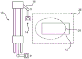
fig. 2 schematically shows a medical X-ray imaging system with a patient access zone according to another example in a top view;
fig. 3 schematically shows another example of a medical imaging system with a laminar flow zone in a side view;
fig. 4 schematically shows an example of a medical imaging system with a standby position and a parking position in a top view;
fig. 5 schematically shows an example of a medical imaging system with two pivotable support arms in a side view;
FIG. 6 schematically illustrates a rail arrangement, a rail connector and two support arms as part of another example medical imaging system; and is
Fig. 7 schematically shows an example of an image acquisition arrangement and a support arrangement mounted on top of a C-arm of a medical imaging system.
Detailed Description
Fig. 1 depicts an X-ray based medical imaging system 10 for generating imaging information of a subject 20. The medical imaging system 10 includes a patient support 12 having a longitudinal horizontal extension or direction 22. The rail arrangement 18 has a longitudinal rail direction 24 and is mounted to the support arrangement 16. The support device 16 is movably connected to the image acquisition device 14. The rail arrangement 18 is arranged transversely or orthogonally as shown in fig. 1 with respect to a longitudinal extension 22 of the patient support 12.
The rail arrangement 18 may comprise one or several separate rails, which may be arranged such that the support arrangement 16 is movable along the rails. Instead of a precise orthogonal arrangement of the rail arrangement 18, all other angles (besides a parallel arrangement) with respect to the longitudinal extension 22 of the patient support 12 are also possible. The rail arrangement 18 may also extend vertically above the patient support 12. The image acquisition arrangement 14 is movably connected (e.g., by a hinge) to the support arrangement 16. The image acquisition arrangement 14 may acquire image information of an object of interest 20, which is placed on the patient support 12. Due to the mobility with respect to the support means 16, the image acquisition arrangement 14 may be moved in longitudinal and transverse directions with respect to the object 20. Preferably, the rail arrangement 18, the support arrangement 16 and the image acquisition arrangement 14 comprise dimensions and sizes that allow positioning of the image acquisition system (in particular the X-ray source and the X-ray detector) in all relevant areas of the patient support and/or the object of interest. Support device 16 may include one or more sections or components to allow movement of image capture device 14 in multiple directions. The support means 16 is movable at least along the rail means 18. Also, for example, pivoting in several directions may be possible.
Fig. 2 depicts a rail arrangement 18 comprising two parallel rails having a longitudinal direction 24. The support device 16 is connected to two rails 18 and is movably connected to the image acquisition device 14. Around the patient support 12, a patient access zone 26 is shown. The patient access zone 26 may be considered an area around at least a portion of the patient support 12 for access of equipment and medical personnel to the patient for treatment/intervention. The purpose of the patient access zone 26 may be seen as being important for effective intervention in the sense that sufficient activity space is required for personnel, as well as the necessary space for medical equipment. The patient access zone may cover the entire patient support 12 or only portions of the patient support 12. Although fig. 2 shows a rectangular shape, other shapes are possible. One aspect of fig. 2 is to position the rail arrangement 18 outside of the patient access zone 16. In this way, the rail arrangement 18 and at least a portion of the support arrangement 16 may be maintained outside of an operating or active zone in the vicinity of the object of interest. Furthermore, in another example, the rail arrangement 18 may be arranged above the level of the patient support 12 if seen from a side view. This allows freedom of movement of the personnel and equipment in the patient access zone, since the rail arrangement and part of the support arrangement 16 only require space in the region of the space above the head of the medical personnel.
Fig. 3 shows a medical imaging system 10 comprising another example of a rail arrangement 18, a support arrangement 16 and an image acquisition arrangement 14 connected to each other. The image capture device 14 is shown as a C-arc structure, but may be provided in any other support structure and shape. Furthermore, a laminar flow zone 28 is shown, which covers a portion of the patient support 12. The laminar flow zone 28 is defined by a laminar flow of supply air 52 provided by an external system (not shown). The supply air 52 is typically pre-treated and filtered and fed into an air supply device 50 that includes a supply air outlet 54 that generates an air flow (e.g., in a laminar flow). The shown air supply device comprising the supply air outlet 54 can be seen as one option or possibility for generating a laminar air flow or a down flow. Therefore, the laminar flow zone 28 should be considered independent of the air supply device 50. The image acquisition arrangement may be partially positioned within the laminar flow region 28 for acquisition of medical images. This may lead to interference between the image acquisition device and the laminar air flow and to turbulence, which is generally undesirable. Therefore, the standby position of the image acquisition arrangement should be outside the laminar flow zone, or at least have minimal interference with the laminar air flow. In the parking position of the image acquisition arrangement 14, any equipment of the imaging system should be removed from the laminar flow zone 28.
In an example (not shown in detail), the image acquisition arrangement 14 may be moved to a position in which the image acquisition arrangement 14 does not obstruct or interfere with the work on and around the patient support, but wherein the image acquisition arrangement 14 is still arranged in the gas flow, such that parts and areas of the image acquisition arrangement 14 which are to be arranged near or above the patient are kept clean due to the provided clean gas. Thus, the rail arrangement is arranged outside the air flow zone, while a part of the device is at least partly inside the air flow zone.
The "keep clean" position may be a standby position, or may be set to another position.
Fig. 4 shows an example of a medical imaging system 10 with a rail arrangement 18, a support arrangement 16 and an image acquisition arrangement 14. Fig. 4 also shows two separate possible positions of the support means 16 and the image acquisition means 14. The S position describes an alternative position which is advantageous when the device is temporarily not needed and needs to be kept in close proximity to the object of interest to reduce the time needed to reposition the image acquisition arrangement to acquire a new image. In the P position, the image acquisition device 14 and the support device 16 are arranged to make or provide maximum space around the active or operational area and to remove the imaging system (if it is not needed). The patient support 12 is partially covered or surrounded by the laminar flow region 28 and the patient access region 26. With regard to the S position (standby position), the image acquisition arrangement 14 is positioned outside the patient access zone 26, however, the image acquisition arrangement 14 may also be partially positioned within the laminar flow zone 28. The illustrated shape and size of the laminar flow region 28 may vary, and the size of the patient access region 26 may also extend, or partially overlap one another. The shape of the laminar flow region 28 and the patient access region 26 may also vary depending on the room space, laminar flow generation methods and apparatus, the shape and size of the patient support 12, and other factors.
Fig. 5 shows an example of the medical imaging system 10, including the rail arrangement 18, the first horizontal support arm 16a, the second vertical support arm 16b, and the image acquisition connector 32. The support arm 16a is pivotally connected to a rail coupler 30 that provides a mechanical connection between the support arm 16a and the rail assembly 18. The support arm 16a is pivotally movable about a vertical axis 34. The term "vertical" relates to a downwardly oriented direction which may deviate from an exact vertical arrangement. The support arm 16a extends horizontally; however, it may also extend in both the vertical and horizontal directions. It should be noted that the function of the support arm 16a is to bridge a horizontal distance, so that at least a certain horizontal extension is necessary to provide the necessary offset or distance of the two pivot axes 34 and 36. The rail coupler 30 is slidable along a longitudinal rail extension of the rail assembly 18. The second support arm 16b is pivotally mounted about a vertical axis 36. Here, deviations of plus 30 degrees to minus 30 degrees from the exact vertical position are also possible, for example up to 60 degrees. In addition to rotational movement, the support arm 16b may also move in all other directions relative to the horizontal support arm 16 a. The image acquisition connection 32 provides for movement of the image acquisition device about the horizontal axis 31, also referred to as "propeller movement". In another example, further pivotal movement of the image acquisition arrangement relative to the second support arm 16b is also possible in three dimensions. Horizontal axis refers to a generally horizontal arrangement that may allow for a negative 30 degrees to a positive 30 degrees deviation from a perfectly horizontal position.
Fig. 6 schematically illustrates the rail arrangement 18, the rail connection 30, the mounting point 38 of the rail connection at the first horizontal support arm 16a, and the mounting point 40 of the second support arm 16b at the first support arm 16 a. The first support arm 16a is pivotally mounted to the rail connector 30 about axis 34. The second support arm 16b is pivotally mounted to the first support arm 16a about axis 36. The horizontal distance 42 between the two axes 34 and 36 is adjustable. This may be accomplished by moving the first mounting point 38 of the rail connector 30 along the extension of the first support arm 16a, and/or by changing or moving or offsetting the mounting point 40 of the second support arm 16b along the length of the horizontal support arm 16 a. By varying or adjusting this distance 42, a horizontal displacement or movement of the image acquisition arrangement can be achieved. Due to the lateral arrangement of the rail arrangement 18, it is provided to change the horizontal position of the image acquisition device 14 to reach the area of the patient support 12 for image acquisition purposes. For example, the adjustment or change of distance 42 in combination with the rotation or pivoting about axes 34 and 36 may provide the necessary degree of flexibility to position the imaging system accordingly.
In fig. 7, an alternative option for mounting the support arm 16b to the top side of the C-shaped arc 41 by means of the image acquisition connection 32 is shown. The C-arm 41 further comprises an X-ray source 44 and a detector 46 arranged opposite the X-ray source 44. The image acquisition linkage 32 allows for pivotal movement of the C-shaped arc about the vertical axis 50. In addition, the image acquisition connector 32 allows for sliding or gliding of the C-arc in a radial direction, performing a substantially circular movement of the X-ray source 44/detector 46 arrangement.
It should be noted that embodiments of the invention have been described with reference to different embodiments. However, the person skilled in the art will conclude from the above and the following description: any combination between features associated with different embodiments should be considered to have been disclosed in the present application, unless otherwise indicated. However, all features may be combined, providing synergistic effects beyond a simple superposition of the features.
While the invention has been illustrated and described in detail in the drawings and foregoing description, such illustration and description are to be considered illustrative or exemplary and not restrictive. The invention is not limited to the disclosed embodiments. Other variations to the disclosed embodiments can be understood and effected by those skilled in the art in practicing the claimed invention, from a study of the drawings, the disclosure, and the appended claims.
In the claims, the word "comprising" does not exclude other elements or steps, and the indefinite article "a" or "an" does not exclude a plurality. A single processor or other unit may fulfill the functions of several items recited in the claims. The mere fact that certain measures are recited in mutually different dependent claims does not indicate that a combination of these measures cannot be used to advantage. Any reference signs in the claims shall not be construed as limiting the scope.
Claims (9)
1. A medical X-ray imaging system (10), comprising:
a patient support (12);
an X-ray image acquisition device (14), the image acquisition device (14) comprising a C-arm (41) having an X-ray source (44) and an X-ray detector (46) disposed at opposite ends;
a support device (16), the support device (16) having a rail connection (30), an image acquisition connection (32) and at least two support arms (16a, 16 b);
a rail arrangement (18);
the image acquisition arrangement (14) acquires image information of an object of interest (20) arranged on the patient support (12);
the rail arrangement (18) is arranged overhead;
-the support means (16) is movably mounted to the rail means (18), wherein the support means (16) is at least movable along the rail means (18);
the rail connector (30) couples the support device (16) to the rail device (18);
the image acquisition connection (32) couples the image acquisition device (14) to the support device (16); and is
The support arms (16a, 16b) being movably connected to each other, connecting the image acquisition connection (32) to the rail connection (30);
a first horizontal support arm (16a) is pivotally mounted to the rail connector (30) at a first mounting point about a first downwardly oriented axis (34);
a second vertical support arm (16b) is pivotally mounted at a first end to the first horizontal support arm (16a) at a second mounting point about a second downwardly oriented axis (36);
at least one of the first mounting point and the second mounting point is movable along the first horizontal support arm to adjust a horizontal distance between the first mounting point and the second mounting point;
the image acquisition connection (32) being mounted at a second end to the second vertical support arm (16b), wherein the image acquisition device (14) is movable relative to the second vertical support arm (16 b);
the image acquisition arrangement (14) is movably mounted to the support arrangement (16) to allow image acquisition of the object of interest (20) from different directions;
the patient support (12) has a longitudinal direction (22); and is
The rail arrangement (18) extends in a longitudinal rail direction (24) transverse to the longitudinal direction (22) of the patient support.
2. The imaging system (10) according to claim 1, wherein the rail arrangement (18) is disposed above the patient support (12) and to the side of the patient support (12).
3. The imaging system (10) of claim 1 or 2, wherein the patient support (12) is at least partially surrounded by a predetermined patient access zone (26); and is
The rail arrangement (18) is disposed above the patient access zone (26) and outside of the patient access zone (26).
4. The imaging system (10) according to claim 1 or 2, characterized in that the patient support (12) is at least partially arranged in a predetermined laminar flow zone (28); and is
The rail arrangement (18) is arranged outside the laminar flow zone (28).
5. The imaging system (10) according to claim 4, characterized in that the support device (16) is adapted to position the image acquisition device (14) at least:
an operating position in which the image acquisition device (14) acquires image information of the object of interest (20); and
a parking position in which the image acquisition device (14) is arranged outside the patient access zone (26) and/or outside the laminar flow zone (28).
6. The imaging system (10) according to claim 1 or 2, characterized in that the support device (16) allows positioning the image acquisition device (14) in a standby position in which the image acquisition device (14) is outside the patient access zone (26).
7. The imaging system (10) of claim 1 or 2,
the C-arm (41) is movably mounted to the image acquisition connection (32); and is
The mounting of the C-arm (41) is arranged to:
I) a middle portion side midway between the opposite ends of the C-arm (41); wherein the image acquisition connection (32) provides a pivoting movement of the C-arm (41) about a horizontal axis (31); or
II) atop the upper ends of the two said opposite ends; wherein the image acquisition connection (32) provides a pivoting movement of the C-arm (41) about a vertical axis (50).
8. The imaging system (10) of claim 1 or 2, further comprising:
an air supply device (50) providing treated supply air (52);
wherein a supply air outlet (54) is provided overhead, supplying the supply air (52) towards the patient support (12) in a laminar air flow, thereby defining a laminar flow zone (28).
9. The imaging system (10) of claim 8, further comprising at least one of the group consisting of:
a movable lighting device;
a movable display device; and
a media shelf;
wherein the lighting device and/or display device and/or media shelf is mounted over the head outside the laminar flow zone.
Applications Claiming Priority (3)
| Application Number | Priority Date | Filing Date | Title |
|---|---|---|---|
| EP13151572.8 | 2013-01-17 | ||
| EP13151572 | 2013-01-17 | ||
| PCT/EP2014/050744 WO2014111437A1 (en) | 2013-01-17 | 2014-01-16 | Ceiling suspension system |
Publications (2)
| Publication Number | Publication Date |
|---|---|
| CN104936522A CN104936522A (en) | 2015-09-23 |
| CN104936522B true CN104936522B (en) | 2020-06-16 |
Family
ID=47631286
Family Applications (1)
| Application Number | Title | Priority Date | Filing Date |
|---|---|---|---|
| CN201480005005.1A Expired - Fee Related CN104936522B (en) | 2013-01-17 | 2014-01-16 | Ceiling suspension system |
Country Status (5)
| Country | Link |
|---|---|
| US (1) | US9980688B2 (en) |
| EP (1) | EP2945541A1 (en) |
| JP (1) | JP2016502926A (en) |
| CN (1) | CN104936522B (en) |
| WO (1) | WO2014111437A1 (en) |
Families Citing this family (5)
| Publication number | Priority date | Publication date | Assignee | Title |
|---|---|---|---|---|
| US9980688B2 (en) | 2013-01-17 | 2018-05-29 | Koninklijke Philips N.V. | Ceiling suspension system |
| JP6736562B2 (en) * | 2015-01-20 | 2020-08-05 | コーニンクレッカ フィリップス エヌ ヴェKoninklijke Philips N.V. | Medical imaging with integrated air guide |
| JP6608414B2 (en) * | 2017-11-13 | 2019-11-20 | キヤノンメディカルシステムズ株式会社 | X-ray diagnostic apparatus and angio CT apparatus |
| JP6968855B2 (en) * | 2017-11-13 | 2021-11-17 | キヤノンメディカルシステムズ株式会社 | X-ray diagnostic device |
| EP3501472A1 (en) * | 2017-12-20 | 2019-06-26 | Koninklijke Philips N.V. | Aerodynamic rail covers |
Citations (6)
| Publication number | Priority date | Publication date | Assignee | Title |
|---|---|---|---|---|
| CN1161190A (en) * | 1995-11-24 | 1997-10-08 | 株式会社日立医药 | X rays photoing system and method for controlling same |
| JP2001029337A (en) * | 1999-07-23 | 2001-02-06 | Shimadzu Corp | X-ray radiographing stand |
| CN1433738A (en) * | 2002-01-22 | 2003-08-06 | 株式会社东芝 | Medical image diagnosis apparatus with multi-monitor |
| CN1663529A (en) * | 2004-03-05 | 2005-09-07 | 株式会社东芝 | X-ray diagnostic apparatus |
| CN101351074A (en) * | 2007-07-19 | 2009-01-21 | 西门子公司 | Biplane x-ray system |
| CN102271586A (en) * | 2009-01-13 | 2011-12-07 | 皇家飞利浦电子股份有限公司 | Stand for an X-ray examination apparatus |
Family Cites Families (20)
| Publication number | Priority date | Publication date | Assignee | Title |
|---|---|---|---|---|
| US5050204A (en) | 1989-05-04 | 1991-09-17 | Siczek Bernard W | C-arm diagnostic equipment |
| DE4214087C1 (en) * | 1992-04-29 | 1993-05-27 | Siemens Ag, 8000 Muenchen, De | System for holding X=ray transmitter and receiver - has two C=shaped curved arms, one for carrying the transmitter and receiver and the other for carrying the first arm |
| DE19623115A1 (en) | 1996-06-10 | 1997-12-11 | Siemens Ag | X-ray device with ceiling mounting |
| DE19839620B4 (en) | 1998-08-31 | 2005-03-24 | Siemens Ag | Medical x-ray system, in particular angiography system |
| JP4481392B2 (en) * | 1999-07-27 | 2010-06-16 | 株式会社東芝 | X-ray diagnostic equipment |
| JP2001137221A (en) * | 1999-11-12 | 2001-05-22 | Ge Medical Systems Global Technology Co Llc | Biplane angiography and ct apparatus |
| DE19958864A1 (en) * | 1999-12-07 | 2001-06-13 | Philips Corp Intellectual Pty | X-ray device |
| DE10109754B4 (en) * | 2001-02-28 | 2004-12-09 | Siemens Ag | Universal x-ray machine |
| DE10161322B4 (en) | 2001-12-13 | 2009-04-02 | Siemens Ag | X-ray equipment |
| JP2003289475A (en) * | 2002-01-22 | 2003-10-10 | Toshiba Corp | X-ray diagnosing apparatus, and display apparatus |
| DE10215982A1 (en) * | 2002-04-11 | 2003-11-06 | Siemens Ag | Medical X-ray stem is mounted from a ceiling using a gantry arrangement with a system of two cantilever arms to which an X-ray C-frame is attached enabling very flexible positioning relative to the patient bed |
| JP4268791B2 (en) * | 2002-10-16 | 2009-05-27 | 株式会社東芝 | X-ray diagnostic equipment |
| US8047715B2 (en) | 2006-11-03 | 2011-11-01 | Koninklijke Philips Electronics N.V. | Multiple rotation C-arm |
| US8352059B2 (en) | 2007-04-19 | 2013-01-08 | Damvig Develop Future Aps | Method for the manufacturing of a reproduction of an encapsulated head of a foetus and objects obtained by the method |
| WO2009036174A2 (en) | 2007-09-13 | 2009-03-19 | Henderson Toby D | Imaging positioning system having robotically positioned d-arm |
| WO2009110906A1 (en) | 2008-03-07 | 2009-09-11 | General Electric Company | A method and arrangement for a mobile imaging system |
| WO2010137116A1 (en) | 2009-05-26 | 2010-12-02 | 三菱電機株式会社 | Apparatus for packing power semiconductor device |
| EP2695027B1 (en) | 2011-04-06 | 2015-08-12 | Koninklijke Philips N.V. | Safety in dynamic 3d healthcare environment |
| JP6017118B2 (en) * | 2011-05-19 | 2016-10-26 | 鹿島建設株式会社 | Air conditioning system |
| US9980688B2 (en) | 2013-01-17 | 2018-05-29 | Koninklijke Philips N.V. | Ceiling suspension system |
-
2014
- 2014-01-16 US US14/655,956 patent/US9980688B2/en not_active Expired - Fee Related
- 2014-01-16 EP EP14700667.0A patent/EP2945541A1/en not_active Withdrawn
- 2014-01-16 WO PCT/EP2014/050744 patent/WO2014111437A1/en active Application Filing
- 2014-01-16 JP JP2015553066A patent/JP2016502926A/en active Pending
- 2014-01-16 CN CN201480005005.1A patent/CN104936522B/en not_active Expired - Fee Related
Patent Citations (6)
| Publication number | Priority date | Publication date | Assignee | Title |
|---|---|---|---|---|
| CN1161190A (en) * | 1995-11-24 | 1997-10-08 | 株式会社日立医药 | X rays photoing system and method for controlling same |
| JP2001029337A (en) * | 1999-07-23 | 2001-02-06 | Shimadzu Corp | X-ray radiographing stand |
| CN1433738A (en) * | 2002-01-22 | 2003-08-06 | 株式会社东芝 | Medical image diagnosis apparatus with multi-monitor |
| CN1663529A (en) * | 2004-03-05 | 2005-09-07 | 株式会社东芝 | X-ray diagnostic apparatus |
| CN101351074A (en) * | 2007-07-19 | 2009-01-21 | 西门子公司 | Biplane x-ray system |
| CN102271586A (en) * | 2009-01-13 | 2011-12-07 | 皇家飞利浦电子股份有限公司 | Stand for an X-ray examination apparatus |
Also Published As
| Publication number | Publication date |
|---|---|
| CN104936522A (en) | 2015-09-23 |
| WO2014111437A1 (en) | 2014-07-24 |
| US9980688B2 (en) | 2018-05-29 |
| EP2945541A1 (en) | 2015-11-25 |
| US20150342547A1 (en) | 2015-12-03 |
| JP2016502926A (en) | 2016-02-01 |
Similar Documents
| Publication | Publication Date | Title |
|---|---|---|
| EP1727466B1 (en) | Arrangement comprising an X-ray tube secured to a ceiling mount | |
| CN104936522B (en) | Ceiling suspension system | |
| US11103990B2 (en) | System and method for mounting a robotic arm in a surgical robotic system | |
| US7597473B2 (en) | X-ray recording device with an X-ray detector and an X-ray emitter | |
| US6416219B1 (en) | Treatment-diagnostic apparatus having a positioning device for a patient | |
| US8424133B1 (en) | Iso-roll table | |
| US20130111666A1 (en) | Patient positioning support structure | |
| US8591107B2 (en) | Stand for an X-ray examination apparatus | |
| EP3322343B1 (en) | Device for remote fluoroscopy, nearby fluoroscopy and radiology | |
| US20160183898A1 (en) | A mammographic device | |
| EP2946759A1 (en) | Medical equipment support system fitted between floor and ceiling | |
| US10080536B2 (en) | Supply device and method for a mobile imaging device | |
| US6935780B2 (en) | Medical apparatus having a support table for treatment and/or examination of a subject thereon | |
| US5086447A (en) | Overhead X-ray apparatus for imaging in bi-plane configuration | |
| WO2014198869A1 (en) | Ceiling suspension system | |
| US20070280425A1 (en) | Ceiling-Mounted X-Ray Examination Device | |
| US7938578B2 (en) | Positioning of an x-ray apparatus | |
| CN108903960B (en) | Bearing device | |
| US20240032883A1 (en) | Cable routing for a computed tomography system |
Legal Events
| Date | Code | Title | Description |
|---|---|---|---|
| PB01 | Publication | ||
| C10 | Entry into substantive examination | ||
| SE01 | Entry into force of request for substantive examination | ||
| GR01 | Patent grant | ||
| GR01 | Patent grant | ||
| CF01 | Termination of patent right due to non-payment of annual fee |
Granted publication date: 20200616 Termination date: 20210116 |
|
| CF01 | Termination of patent right due to non-payment of annual fee |