CN1049232A - The film loader of band film-exposure status indicator - Google Patents
The film loader of band film-exposure status indicator Download PDFInfo
- Publication number
- CN1049232A CN1049232A CN90104893A CN90104893A CN1049232A CN 1049232 A CN1049232 A CN 1049232A CN 90104893 A CN90104893 A CN 90104893A CN 90104893 A CN90104893 A CN 90104893A CN 1049232 A CN1049232 A CN 1049232A
- Authority
- CN
- China
- Prior art keywords
- film
- shell
- indicator
- loader
- magazine shell
- Prior art date
- Legal status (The legal status is an assumption and is not a legal conclusion. Google has not performed a legal analysis and makes no representation as to the accuracy of the status listed.)
- Granted
Links
Images


Classifications
-
- G—PHYSICS
- G03—PHOTOGRAPHY; CINEMATOGRAPHY; ANALOGOUS TECHNIQUES USING WAVES OTHER THAN OPTICAL WAVES; ELECTROGRAPHY; HOLOGRAPHY
- G03C—PHOTOSENSITIVE MATERIALS FOR PHOTOGRAPHIC PURPOSES; PHOTOGRAPHIC PROCESSES, e.g. CINE, X-RAY, COLOUR, STEREO-PHOTOGRAPHIC PROCESSES; AUXILIARY PROCESSES IN PHOTOGRAPHY
- G03C3/00—Packages of films for inserting into cameras, e.g. roll-films, film-packs; Wrapping materials for light-sensitive plates, films or papers, e.g. materials characterised by the use of special dyes, printing inks, adhesives
-
- G—PHYSICS
- G03—PHOTOGRAPHY; CINEMATOGRAPHY; ANALOGOUS TECHNIQUES USING WAVES OTHER THAN OPTICAL WAVES; ELECTROGRAPHY; HOLOGRAPHY
- G03B—APPARATUS OR ARRANGEMENTS FOR TAKING PHOTOGRAPHS OR FOR PROJECTING OR VIEWING THEM; APPARATUS OR ARRANGEMENTS EMPLOYING ANALOGOUS TECHNIQUES USING WAVES OTHER THAN OPTICAL WAVES; ACCESSORIES THEREFOR
- G03B17/00—Details of cameras or camera bodies; Accessories therefor
- G03B17/28—Locating light-sensitive material within camera
- G03B17/30—Locating spools or other rotatable holders of coiled film
-
- G—PHYSICS
- G03—PHOTOGRAPHY; CINEMATOGRAPHY; ANALOGOUS TECHNIQUES USING WAVES OTHER THAN OPTICAL WAVES; ELECTROGRAPHY; HOLOGRAPHY
- G03B—APPARATUS OR ARRANGEMENTS FOR TAKING PHOTOGRAPHS OR FOR PROJECTING OR VIEWING THEM; APPARATUS OR ARRANGEMENTS EMPLOYING ANALOGOUS TECHNIQUES USING WAVES OTHER THAN OPTICAL WAVES; ACCESSORIES THEREFOR
- G03B2217/00—Details of cameras or camera bodies; Accessories therefor
- G03B2217/26—Holders for containing light-sensitive material and adapted to be inserted within the camera
- G03B2217/263—Details of exposure status indicators; Double exposure prevention
-
- G—PHYSICS
- G03—PHOTOGRAPHY; CINEMATOGRAPHY; ANALOGOUS TECHNIQUES USING WAVES OTHER THAN OPTICAL WAVES; ELECTROGRAPHY; HOLOGRAPHY
- G03B—APPARATUS OR ARRANGEMENTS FOR TAKING PHOTOGRAPHS OR FOR PROJECTING OR VIEWING THEM; APPARATUS OR ARRANGEMENTS EMPLOYING ANALOGOUS TECHNIQUES USING WAVES OTHER THAN OPTICAL WAVES; ACCESSORIES THEREFOR
- G03B2217/00—Details of cameras or camera bodies; Accessories therefor
- G03B2217/26—Holders for containing light-sensitive material and adapted to be inserted within the camera
- G03B2217/266—Thrust-type cartridges
Abstract
A kind of film loader (1), wherein film (F) is pushed the exposure of outside the film magazine shell (3) that passes out to airtight lucifuge so that the continuous image district on the film, and film can return in the film magazine shell after the exposure before all image domain burn-outs or in fact fully.According to the present invention, a film-exposure status indicator (77) is supported on the film magazine shell (3), can move in succession the second and the 3rd position from normal primary importance with respect to shell, thereby three kinds of visible indications are provided respectively, promptly film (F) is: generally unexposed; Before all exposed in the image domain, turned back in the shell; Exposure in fact fully.
Description
Present invention relates in general to the field of camera work, a kind of film loader of film particularly is housed.More particularly, the present invention relates to a kind ofly have the film of informing in cameraman's film loader and be in part exposure, exposure or generally speaking without the film loader of the indicating device of exposure status fully haply.
In the film loader (for example film loader of Eastman Kodak Co and photographic film company limited of Fuji manufacturing) that each manufacturing firm of common 35 mm film produces, film system is wound on the flanged pin spool that is rotatably supported in the cylindrical outer casing.Film is at the general always outstanding film magazine shell of about 2 and 1/3 inches long leaders or foremost part (being called " head " usually) gently outside the slit used of intermediate plate or the folder mouthful.One end of spool has the axial extension of the weak point of an outstanding shell, and spool can be rotated with hand.If with hand rotating scroll on the reviewing direction, then, still keep motionless, thereby the film in the shell certainly will be to radially expansion and give prominence to outer head (fogged leader) part of slit through ashing because the medial extremity of film is fixed on the spool.Film always radial expansion till non-slip between the interior curved wall of its outmost turns and shell.This non-slip relation is in case existence just has one to prevent that spool from continuing the effect of contraction that rotates in the reviewing direction between film and the shell.Therefore film can not be released outside the shell at reviewing direction rotating scroll, thereby in 35 millimeters general cameras, be caught for film being extracted out the leader that needs outside the shell outstanding.
Someone proposed a kind of 35 mm film boxes, and this film loader and common film loader are different, rotates film spool on the reviewing direction head are run out of outside the film magazine shell automatically.Head then were to be placed in fully in the film magazine shell originally.Specifically, the United States Patent (USP) 4 that on January 3rd, 1984 got permission, 423, a kind of film loader is disclosed in 943, its outmost turns of film that wherein is wound on the film spool is tightly clamped diametrically by two flange corresponding annular projections that are spaced a distance in the axial direction of spool, in case the outmost turns of film contacts with the inwall of film magazine shell.The end of smearing of film is fixed on the film spool, and the front end or the leading end of film then narrow down gradually slightly, so that can freely extend between annular protrusion divides, the inside position of the passage outside film leads to the film magazine shell rests on the shell wall then.Film spool begins in the reviewing rotating process, and the leading end of film needs the inlet of " finding out " film channel.Film enters and by film channel, runs out of the film magazine shell then.If the cameraman rolls up the film of position (promptly film all before in addition expose fully in the position of map) in will being in and rewinds in the film magazine shell because of wanting to change dissimilar films, then head can turn back to the inside position of film channel.At this moment in order to reuse film, exposed in map position that it is remaining, needs the leading end of head to find out inlet towards film channel once more so that run out of the film shell.Film channel is narrower a little than film, thereby film makes it be in the transverse curvature state during reviewing from spool, thereby film edge can be moved freely under each flange annular projection.If but film is to make its longitudinal edge transverse curvature power that motion is subjected under annular protrusion divides too big, then can increase the friction force between film and the film magazine shell, thereby hinder film, film is damaged from the advancing of shell.The leading end of film roughly is that this point has but produced another problem 1 about 1/8 inch to 1 but also 1/4 inch not only (depend on the sheet hole count on the leading end and decide).Under high temperature and/or high humidity environment, the ability that film roll outwards ejects during around spool weakens, and the tendency that film inwardly curls increases.As a result, leading end is owing to may be bent away from shell wall in the longitudinal direction, thereby its is understood and can not enter in the film channel when film spool rotates on the reviewing direction.
In 35 mm film boxes of general manufacturing firm outlet, after the film burn-out, film spool always rotates on advance A, and head are involved in the film magazine shell.Thereafter, owing to head can not be drawn out of outside the film magazine shell because of the effect of contraction between film and the shell, thereby this can be used as the film indication of burn-out usually.On the contrary, at United States Patent (USP) 4,423, in the 943 disclosed film loaders, rotate film spool in the reviewing direction head are run out of outside the film magazine shell automatically.As long as the film leading end can enter in the film channel of shell, then no matter film is without exposing, all exposed to the sun the light or the light that partly exposed to the sun, can both accomplishing this point.Therefore film loader does not provide the indication of film-exposure status.
The present invention disclosed herein is the most desirable to be implemented in 35 mm film boxes.Because all characteristics of this class film loader are normally well-known, therefore only highlight a part that constitutes disclosure embodiment or the element that directly matches below with embodiment of the present disclosure.But it should be understood that other element that does not specifically illustrate or illustrate may get the known various forms of present technique field those of ordinary skill.
The present invention is to provide a kind of like this film loader, film can be before having exposed in all map positions or film in fact in film loader, deliver to forward outside the close lighttight film magazine shell after the burn-out, so that exposed in turn in each map position of film, and it can be sent back in the film magazine shell.According to the present invention, at film magazine shell upper support a film-exposure status indicator is arranged, so that move on in turn the second and the 3rd position from the primary importance of regulation with respect to shell, thus provide film generally speaking without exposure, film had turned back in the shell before its map position burn-out and the in fact corresponding visible indication of burn-out of film.Film magazine shell and indicator comprise the engagement device that cooperatively interacts, for preventing that indicator from moving on to the usefulness of its first and second position when moving on to its primary importance and external its 3rd position when being in its second place.The best uniaxially resulting indicator of the engagement device that cooperatively interacts is from its primary importance to its second place with the motion from its second place to its 3rd position, and prevents that indicator from shifting out outside the 3rd position.
Fig. 1 is the film loader exploded perspective illustration of the band film-exposure status indicator of a most preferred embodiment of the present invention.
Fig. 2 is the elevation drawing of film loader of the present invention, illustration the film magazine shell of opening, to demonstrate the film that is wound on the spool for film.
Fig. 3 and 4 is section end views of film magazine shell, film and film spool.
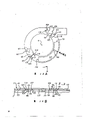
Fig. 5 and 6 is elevation drawing of film and film spool, illustration film leave mode on the film spool in.
Fig. 7 and 8 is and Fig. 5 and 6 similar elevation drawing, illustration the film mode of rewinding from film spool.
Fig. 9 and 10 is exploded perspective illustration of film magazine shell and film-exposure status indicator.
Figure 11 A and 11B are that indicator is in primary importance and shows the actual complete unexposed principle schematic of film.
Figure 12 A and 12B are that indicator is in the principle schematic that the second place shows that film only partly exposes.
Figure 13 A and 13B are that indicator is in the 3rd location tables gelatin volume principle schematic of burn-out in fact.
Each numbering among the figure, 1 is film loader, and 3 is close lighttight film magazine shell, and 77 is the exposure status indicator, and 103,115 is engagement device, but 103,115,119 is the composition surface, but 103,115,121 is the composition surface, 5 is film spool.
Referring to accompanying drawing.Fig. 1 and 2 35 mm film boxes 1 that drawn, it comprises close lighttight film magazine shell 3 and the film spool 5 that can rotate on film reviewing direction U and advance A W in the film magazine shell.Film magazine shell 3 is made up of two and half shells 7 and 9, and both are along separately troughs of belt and be step-like marginal portion 11 and 13 engagements.Half shell 7 and 9 that is meshing has formed the last circular hole 15 and the following circular hole 17 of centering thereon, supplies scroll core or hub 23 two ends than short and long extension 19 and 21 usefulness, and the while, they also formed the film channel 25 that leads to outside the film magazine shell 3.The extension 19 and 21 at scroll core 23 two ends respectively comprises a ring groove 27, ring groove 27 and each circular hole 15 and 29 engagements of 17 respective edges, rotatably support film spool 5, make its film loose winding and on rotate around axis X on volume direction U and the W.Be lined with known black velvet or velvet material in the film channel 25, enter in the film channel with the light around preventing.
The film 33 of 35 mm film F forms a continuous circle circle film on scroll core 23.As shown in Figure 3, film 33 comprises outmost turns 35, and this is the head with leading end or front end 37, also comprises time circle 39 inwardly, is wound on after the outmost turns 35.The inner ring of film 33 inner or drag the end (not shown) and be fixed on the scroll core 23.
Along scroll core 23 be separated by that a segment distance coaxial line disposes that a pair of identical clamping film uses as thin as a wafer and pliable and tough flange 41 and 43, as shown in Fig. 1,2 and 5.Two flanges 41 and 43 comprise integral disc 45 and 47 separately, also comprise separately integral ring-shaped projection or skirt section 49 and 51, form round and stretch out outside each dish.Two dishes 45 and 47 cover film 33 two ends by corresponding longitudinal edge 53 in each successive turn two ends of film and the 55 flat limit (not shown)s that defined, and respectively there is a hole (not shown) at their center, scroll core 23 promptly extends axially by this center pit, and scroll core 23 can be rotated with respect to flange 41 and 43.Referring to Fig. 5.Annular protrusion divides 49 and 51 radially overlapping with this outmost turns 35 outside each longitudinal edge 53 and 55 of film 33 outmost turns (head) 35, so that limit this circle diametrically, thereby thereby prevent its radial expansion or resemble that ejecting the clock spring in fact faces the wall and meditates with the introversion of film magazine shell 3 57 contacts.Along the longitudinal edge 55 of outmost turns (head) 35 near having an otch 59 that holds projection its leading end 37 outside, confession hold the peripheral part 51 of annular projection 51 ' usefulness.Can make like this outmost turns (head) 35 with leading end 37 and otch 59 link up radially outward overlapping than minor face edge part 61 and annular section 51, thereby keep the next 39 one section radial distance D of being separated by that enclose in the leading end and the inside of film 33.Referring to Fig. 3 and 6.Leading end 37 has a leading edge 63, tilts from the longitudinal edge 53 of outmost turns 35 another longitudinal edge 55 to this circle, forms the most preceding tip of this circle or termination 65, and it is the same with edge section 61, and radial outward overlaps onto annular protrusion and divides on 51.See Fig. 5.
The inspection sheet guide 67 that forms with half box 7 is positioned at a porch, inside that enters film channel 25, be seated between the next circle 39 of leading end 37 and the inside of outmost turns (head) 35, in order to have examined leading end and to be introduced in the film channel according to the rotational action of film spool 5 at reviewing direction U.Leading end 37 enters in the film channel 25 advancing above the inspection sheet guide 67 rather than between next circle 39 of inspection sheet guide and the inside because it diametrically with back one circle distance D apart.Therefore as shown in Figure 3, leading end 37 is owing to being positioned at the scope of examining sheet guide 67 with next such segment distance in circle 39 intervals of the inside.
When the leading end 37 of outmost turns (head) 35 is advanced above sheet guide 67 is being examined in the rotation of reviewing direction U according to film spool 5, the longitudinal edge 53 and 55 of this circle begins to make each arch section of two flanges 41 and 43 gently crooked apart from each other in the axial direction, as shown in Figure 8, at first make notch 59 depart from projection 51 ', film 33 each continuous vertical section (from leading end) are come out between each flange, enter outside the film magazine shell 3.Because film is a bit larger tham annular protrusion at the width W F between longitudinal edge 53 and 55 and divides the AS of the axial spacing between 49 and 51, so flange 41 and 43 produces local bending.Film 33 each successive turn have a resistance that will make the resistance that its local bending produces greater than flange 41 and 43 to transverse curvature in addition.The curved support member 69 that a pair of exhibition is stretched from the inwall 57 of film magazine shell 3 extend and since flange 41 and 43 localized axial is crooked and directly be pressed on the continuous arch section of two dishes 45 and 47 apart from each other, thereby make the sweep of each flange return to unbending state under their original normal conditions.
Roughly have an aperture 71 in the outmost turns (head) 35 near its leading end 37 places.The tusk 73 that is fixed on film magazine shell 3 inwalls 57 has one free most advanced and sophisticated 75, it is to prepare to be seated in the aperture 71 that this tip is placed in the there, thereby when advance A W rotates, embed in the outmost turns (head 2) 35 as shown in Figure 4 at film spool 5, when reviewing direction U rotates, run out of outside the aperture as shown in Figure 3 at film spool, thereby do not engage with this circle.Outmost turns 35 rests between the next inner ring 39 of inspection sheet guide 67 and the inside according to the leading end 37 of having avoided this circle that engages that film spool carries out in the rotation of advance A W with tusk 73.
Originally (in camera) is when reviewing direction U rotating scroll core 23, two flanges 41 and 43 are may of short duration maintenances static, and film 33 must radial expansion because its inner is fixed on the scroll core or is resembled loose winding the clock spring, and the annular protrusion of guaranteeing film outmost turns (head) 35 and each flange is non-slip fully between dividing 49 and 51.Flange 41 and 43 is rotated.So the leading end 37 of outmost turns (head) 35 can be advanced above inspection sheet guide 67, impels flange 41 and 43 each continuous curved portions axial bending apart from each other, as shown in Figure 8.This at first make notch 59 can leave projection 51 ', next make film 33 each continuously vertically section (from leading end 37) between each flange, come out to enter outside the film magazine shell 3.
If (in camera) rotates film spool 5 on advance A W before the whole length of film F is exposed fully, and think to use afterwards film to have remaining part now, then to turn to the free end 75 that aperture 71 receives tusks 73 to film spool basically always, thereby make outmost turns 35(head) with till tusk engages.In the time of will using (in the camera) film F to have remaining part now later on, can on reviewing direction U, rotate film spool 5, make outmost turns (head) 35 break away from tusks 73, then film be delivered to forward outside the film magazine shell 3 again.
Fig. 9 and 10 a kind of film-exposure status indicator 77 of annular that drawn, this indicator has a center pit 79, and the neck shape extension 81 of an end is promptly stretched in the center pit 79 in 3 liang of outer ends 83 of film magazine shell and 85.Indicator 77 have three equidistantly radially inwardly the fin 87,89 and 91 of configuration be fixed in the circumferential annular groove 93 of neck shape extension 81, rotate with respect to film magazine shell 3 and film spool 5 around the X-axis line to support indicator.
The design idea of indicator 77 is that it is turned to from original or normal primary importance (seeing Figure 11 A) on advance A W for example in turn the second and the 3rd position (seeing Figure 12 A and 13A), so that visual corresponding indication to be provided: exist film F in the film magazine shell 3 generally speaking without exposure, film had turned back in the shell before exposing fully in its map position already and film has virtually completely exposed to the sun light.For realizing these visual indications, on indicator 77, established a pointer 94, for aliging with three marking " without exposure ", " part exposures " and " exposing " that are printed in order on the film shell 3 respectively.See Fig. 9.(see Figure 11 A) when indicator 77 is in its first position, pointer 94 points to the marking " without exposure ".(see Figure 12 A) when indicator 77 is in its second place, pointer 94 points to the marking " part exposure ".(see Figure 13 A) when indicator 77 is in its 3rd position, pointer 94 points to the marking and " exposes ".
Be provided with the engagement device that cooperatively interacts below the outer end 83 of film magazine shell 3 and the indicator 77, so that uniaxially resulting indicator, make it forward its second place to from its primary importance, forward its 3rd position to, and prevent that indicator from producing outside its 3rd position from the second place at advance A W.Specifically, the engagement device that is located at the outer end 83 of film magazine shell 3 comprises a pair of identical inclined- plane projection 95 and 99, they each have inclined-plane 101 and a steep face 103, and through upwards in line and equidistant with the X-axis line.See Fig. 9,11A and 11B.Be located at indicator 77 following engagement devices and comprise four same inclined-plane projections 105,107,109 and 111, each has inclined-plane 113 and steep face 115, and each and X-axis line are equidistant, in addition, also has a flat pieces 117 that has with same equally spaced two the identical steep faces 121 of X-axis line and 119.See Figure 10,11A and 11B.When being in its first position, indicator (sees Figure 11 A and 11B), the steep face 103 of inclined-plane projection 95 is positioned near the steep face 119 of flat pieces 117, thereby prevent that fully indicator from rotating at reviewing direction U, 103 in the steep face of inclined-plane projection 99 is positioned at 113 opposites, inclined-plane of inclined-plane projection 109, has prevented that leggiero indicator from rotating on advance A W.Therefore indicator 77 is fixed on the primary importance, but can make it move to the second place.If rotation indicator 77 on advance A W at this moment, then the inclined-plane 113 of inclined-plane projection 109 can move above the steep face 103 of inclined-plane projection 99.When indicator 77 is in its second place, as shown in Figure 12 A and 12B, the steep face 103 of inclined-plane projection 95 is located near the steep face 115 of inclined-plane projection 105, prevented that fully indicator from rotating on reviewing direction U, the steep face 103 of inclined-plane projection 99 is positioned at 113 opposites, inclined-plane of inclined-plane projection 111 simultaneously, has prevented that leggiero indicator from rotating on advance A W.Therefore indicator is fixed on the second place, but it is moved on on the 3rd position.If rotation indicator 77 on advance A W at this moment, then the inclined-plane 113 of inclined-plane projection 111 can be mobile on the steep face 103 of inclined-plane projection 99.When indicator 77 is in its 3rd position, shown in Figure 13 A and 13B, the steep face 103 of inclined-plane projection 95 is located near the steep face 115 of inclined-plane projection 107, prevented that fully indicator from rotating on reviewing direction U, the steep face 103 of inclined-plane projection 99 is positioned near the steep face 121 of flat pieces 117 simultaneously, has prevented that fully indicator from rotating on advance A W.So just indicator 77 can not be moved on to outside the 3rd position.
Above the present invention describes with regard to a most preferred embodiment.But it should be understood that on the basis that does not depart from the scope of the present invention, be familiar with those skilled in the art and can carry out various modifications and change with regard to the present invention.For example, except that the first and second and the 3rd position, indicator can also have other position for providing and exposing relevant or he plants information.
We think that the present invention can solve the problem of the film loader of above-mentioned relevant band film-exposure status indicator.
Claims (7)
1, a kind of film loader, wherein film with pushed outside close lighttight film magazine shell, so that make map position exposure one by one on the film, but also can be before the position burn-out of described map, or film sends back to film in the described film magazine shell after the burn-out in fact, it is characterized in that:
Described film magazine shell upper support has a film-exposure status indicator, can move on to another position that the visual indication that described film exposed is provided from the position that the unexposed visual indication still of described film is provided with respect to shell; And
Described film magazine shell and described indicator comprise the engagement device of the work of being fitted to each other, for preventing that indicator from turning back to another position when being in a position.
2, film loader as claimed in claim 1, it is characterized in that, but the engagement device of the described work that is fitted to each other comprises and is positioned on described film magazine shell and the described indicator corresponding composition surface, for the motion of uniaxially resulting indicator from position to another position.
3, film loader as claimed in claim 1 or 2 is characterized in that, but the engagement device of the described work that is fitted to each other comprises the composition surface that is positioned on described film magazine shell and the described indicator, for preventing to shift out outside this position when indicator is in a position.
4, film loader as claimed in claim 1, it is characterized in that, described film leaves on the film spool with the form of film, film spool then is bearing between interior shell two outer ends of film magazine shell, thereby so that film is delivered to outside the shell in the rotation of reviewing direction, thereby and rotate in advance A film sent back in the shell, and described indicator is bearing on one of them described outer end of shell, so that coaxially turn on another position from a position with respect to described film spool.
5, film loader as claimed in claim 4 is characterized in that, the engagement device uniaxially of the described work that cooperatively interacts limits described indicator and turn to another position from a position on the reviewing direction or on advance A.
6, film loader as claimed in claim 5 is characterized in that, the engagement device of the described work that cooperatively interacts prevents to rotate on reviewing and advance A when described indicator is in the another location.
7, a kind of film loader, wherein film with pushed outside close lighttight film magazine shell, so that make map position exposure one by one on the film, but also can be before the position burn-out of described map or film after the burn-out film is sent back in the described film magazine shell in fact, it is characterized in that:
Described film magazine shell upper support has a film-exposure status indicator, can with respect to shell from provide described film generally speaking unique primary importance of unexposed visual indication still move on to and provide film before its all map position burn-outs, to get back on unique second place of the visual indication in the shell, and move on to and provide film in fact on the 3rd unique position of the visual indication of burn-out.
Applications Claiming Priority (2)
| Application Number | Priority Date | Filing Date | Title |
|---|---|---|---|
| US07/384,332 US4978985A (en) | 1989-07-24 | 1989-07-24 | Film cassette having film-exposure status indicator |
| US384,332 | 1989-07-24 |
Publications (2)
| Publication Number | Publication Date |
|---|---|
| CN1049232A true CN1049232A (en) | 1991-02-13 |
| CN1025374C CN1025374C (en) | 1994-07-06 |
Family
ID=23516917
Family Applications (1)
| Application Number | Title | Priority Date | Filing Date |
|---|---|---|---|
| CN90104893A Expired - Fee Related CN1025374C (en) | 1989-07-24 | 1990-07-24 | Film cassette having film-exposure status indicator |
Country Status (14)
| Country | Link |
|---|---|
| US (1) | US4978985A (en) |
| EP (1) | EP0413968B1 (en) |
| JP (1) | JPH0375741A (en) |
| KR (1) | KR910003434A (en) |
| CN (1) | CN1025374C (en) |
| AU (1) | AU634256B2 (en) |
| BR (1) | BR9003563A (en) |
| CA (1) | CA2020637A1 (en) |
| DE (1) | DE69015505T2 (en) |
| ES (1) | ES2065443T3 (en) |
| HK (1) | HK82596A (en) |
| MX (1) | MX164182B (en) |
| MY (1) | MY105937A (en) |
| SG (1) | SG59876G (en) |
Cited By (2)
| Publication number | Priority date | Publication date | Assignee | Title |
|---|---|---|---|---|
| US8409820B2 (en) | 2009-08-31 | 2013-04-02 | Massachusetts Institute Of Technology | Kinase sensors |
| US8586570B2 (en) | 2006-08-28 | 2013-11-19 | Massachusetts Institute Of Technology | Sox-based kinase sensor |
Families Citing this family (20)
| Publication number | Priority date | Publication date | Assignee | Title |
|---|---|---|---|---|
| DE69017558T2 (en) * | 1989-08-25 | 1995-07-06 | Fuji Photo Film Co Ltd | Cassette for a photographic film. |
| US5219418A (en) * | 1990-03-21 | 1993-06-15 | Agfa-Gevaert N. V. | Light-tight cassette |
| US5064134A (en) * | 1990-05-07 | 1991-11-12 | Eastman Kodak Company | Film cassette with film exposure status indicator |
| US5065952A (en) * | 1990-05-29 | 1991-11-19 | Eastman Kodak Company | Film cassette with film exposure status indicator |
| US5048770A (en) * | 1990-05-29 | 1991-09-17 | Eastman Kodak Company | Film cassette with exposure status indicator |
| US5106030A (en) * | 1990-07-31 | 1992-04-21 | Eastman Kodak Company | Film cassette with exposure status indicator |
| US5032854A (en) * | 1990-07-31 | 1991-07-16 | Eastman Kodak Company | Photographic film cassette and camera apparatus and method |
| US5030978A (en) * | 1990-09-12 | 1991-07-09 | Eastman Kodak Company | Photographic film cassette |
| US5234174A (en) * | 1991-04-03 | 1993-08-10 | Eastman Kodak Company | Film cassette with film speed related indicator |
| JPH04365033A (en) * | 1991-06-11 | 1992-12-17 | Fuji Photo Film Co Ltd | Photographic film cartridge |
| EP0644457B1 (en) * | 1993-09-17 | 1997-05-21 | Agfa-Gevaert N.V. | A lighttight film package |
| CA2135324A1 (en) * | 1994-11-08 | 1996-05-09 | Bernard W. N. Lee | Film cassette spool with exposure indicator |
| US5552849A (en) * | 1995-01-23 | 1996-09-03 | Eastman Kodak Company | Visual exposure indicating system |
| US5829853A (en) * | 1995-12-04 | 1998-11-03 | Nikon Corporation | Film image signal outputting apparatus |
| US5893000A (en) * | 1996-01-31 | 1999-04-06 | Fuji Photo Film Co., Ltd. | Camera capable of reading/writing information of photo film cassette |
| JPH09219818A (en) * | 1996-02-09 | 1997-08-19 | Nikon Corp | Film image display |
| JP3586028B2 (en) * | 1996-03-01 | 2004-11-10 | 富士写真フイルム株式会社 | Film unit with lens |
| US5715494A (en) * | 1996-04-03 | 1998-02-03 | Eastman Kodak Company | Film cartridge with film-exposed visual indicator |
| US6007260A (en) * | 1996-11-07 | 1999-12-28 | Eastman Kodak Company | Film exposure status indicator for a film cartridge |
| US6019302A (en) * | 1998-10-08 | 2000-02-01 | International Business Machines Corp. | Method and apparatus for indicating end of useful life for tape cartridges |
Family Cites Families (25)
| Publication number | Priority date | Publication date | Assignee | Title |
|---|---|---|---|---|
| US1685010A (en) * | 1925-12-11 | 1928-09-18 | Thornton John Edward | Spool case for cameras and for cinematograph and similar projection apparatus |
| US2367514A (en) * | 1942-06-30 | 1945-01-16 | Eastman Kodak Co | Exposure indicating spool and camera support therefor |
| US2511383A (en) * | 1945-08-06 | 1950-06-13 | W W Boes Company | Cassette |
| US2591417A (en) * | 1950-03-08 | 1952-04-01 | Frye Jack | Roll film camera |
| BE625911A (en) * | 1959-08-19 | |||
| US3467341A (en) * | 1966-11-01 | 1969-09-16 | Eastman Kodak Co | Rim trap for photographic film projection cartridge |
| DE6753703U (en) * | 1968-08-30 | 1969-06-19 | Agfa Gevaert Ag | FRAME COUNTER FOR ROLLED FILM CASSETTE OR CAMERA |
| US3645385A (en) * | 1969-06-20 | 1972-02-29 | Eastman Kodak Co | Openable cartridge for facilitating egress and ingress of strip material |
| US3747865A (en) * | 1971-03-10 | 1973-07-24 | Brady Co W H | Web processing cartridges |
| DE2159858C3 (en) * | 1971-12-02 | 1981-09-17 | Hans 1000 Berlin Domnick | Film cassette |
| US3784001A (en) * | 1972-02-14 | 1974-01-08 | Eastman Kodak Co | Anticlockspring connector |
| US3768894A (en) * | 1972-06-12 | 1973-10-30 | Polaroid Corp | Photographic cassette containing film strip programmed for manual and automatic operation and film processor therefor |
| US3836984A (en) * | 1973-04-09 | 1974-09-17 | Bell & Howell Co | Light sealed film cartridge |
| JPS5531541A (en) * | 1978-08-23 | 1980-03-05 | Toshiba Mach Co Ltd | Abnormality detecting system for cutting tool |
| JPS56154720A (en) * | 1980-05-02 | 1981-11-30 | Olympus Optical Co Ltd | Film cassette |
| DE3019664A1 (en) * | 1980-05-22 | 1981-11-26 | Agfa-Gevaert Ag, 5090 Leverkusen | FILM TAPE FOR A FILM STRIP SUITABLE FOR TAKING SEVERAL IMAGES |
| US4311377A (en) * | 1980-07-08 | 1982-01-19 | Eastman Kodak Company | Identifying cassettes loaded in cameras |
| US4338015A (en) * | 1981-03-03 | 1982-07-06 | Polaroid Corporation | 35 mm Cassette with film rewind limit, exposure indicator, and film release |
| US4423943A (en) * | 1982-04-02 | 1984-01-03 | Polaroid Corporation | Photographic film assemblage having a non-lighttight film withdrawal opening |
| US4653888A (en) * | 1985-03-29 | 1987-03-31 | Komamura Photographic Co., Ltd. | Indicator for indicating the presence or absence of a photo sensitive material in a film holder |
| US4678300A (en) * | 1985-09-12 | 1987-07-07 | Eastman Kodak Company | Apparatus and method for identifying a film cartridge used in a particular type camera |
| US4647170A (en) * | 1985-09-30 | 1987-03-03 | Eastman Kodak Company | Apparatus and method for identifying a film cartridge |
| US4682870A (en) * | 1986-01-13 | 1987-07-28 | Eastman Kodak Company | Apparatus for encoding a film cartridge used in a particular type camera |
| US4806960A (en) * | 1988-01-11 | 1989-02-21 | Eastman Kodak Company | Cassette information controller and memory |
| JPH01233431A (en) * | 1988-03-15 | 1989-09-19 | Nikon Corp | Camera with used cartridge discriminating device |
-
1989
- 1989-07-24 US US07/384,332 patent/US4978985A/en not_active Expired - Fee Related
-
1990
- 1990-07-06 CA CA002020637A patent/CA2020637A1/en not_active Abandoned
- 1990-07-18 AU AU59107/90A patent/AU634256B2/en not_active Ceased
- 1990-07-20 ES ES90113941T patent/ES2065443T3/en not_active Expired - Lifetime
- 1990-07-20 EP EP90113941A patent/EP0413968B1/en not_active Expired - Lifetime
- 1990-07-20 DE DE69015505T patent/DE69015505T2/en not_active Expired - Fee Related
- 1990-07-20 SG SG1995905485A patent/SG59876G/en unknown
- 1990-07-23 KR KR1019900011196A patent/KR910003434A/en active IP Right Grant
- 1990-07-23 MX MX21685A patent/MX164182B/en unknown
- 1990-07-23 BR BR909003563A patent/BR9003563A/en unknown
- 1990-07-24 MY MYPI90001230A patent/MY105937A/en unknown
- 1990-07-24 CN CN90104893A patent/CN1025374C/en not_active Expired - Fee Related
- 1990-07-24 JP JP2196043A patent/JPH0375741A/en active Pending
-
1996
- 1996-05-09 HK HK82596A patent/HK82596A/en not_active IP Right Cessation
Cited By (2)
| Publication number | Priority date | Publication date | Assignee | Title |
|---|---|---|---|---|
| US8586570B2 (en) | 2006-08-28 | 2013-11-19 | Massachusetts Institute Of Technology | Sox-based kinase sensor |
| US8409820B2 (en) | 2009-08-31 | 2013-04-02 | Massachusetts Institute Of Technology | Kinase sensors |
Also Published As
| Publication number | Publication date |
|---|---|
| JPH0375741A (en) | 1991-03-29 |
| MX164182B (en) | 1992-07-22 |
| AU634256B2 (en) | 1993-02-18 |
| DE69015505T2 (en) | 1995-07-13 |
| CA2020637A1 (en) | 1991-01-25 |
| ES2065443T3 (en) | 1995-02-16 |
| EP0413968A1 (en) | 1991-02-27 |
| CN1025374C (en) | 1994-07-06 |
| KR910003434A (en) | 1991-02-27 |
| DE69015505D1 (en) | 1995-02-09 |
| SG59876G (en) | 1995-09-01 |
| MY105937A (en) | 1995-02-28 |
| BR9003563A (en) | 1991-08-27 |
| AU5910790A (en) | 1991-01-24 |
| EP0413968B1 (en) | 1994-12-28 |
| US4978985A (en) | 1990-12-18 |
| HK82596A (en) | 1996-05-17 |
Similar Documents
| Publication | Publication Date | Title |
|---|---|---|
| CN1025374C (en) | Film cassette having film-exposure status indicator | |
| AU616842B2 (en) | Film cassette | |
| EP0386625B1 (en) | Film cassette | |
| US4832275A (en) | Film cassette | |
| KR0142226B1 (en) | Camera apparatus for preventing load of exposed film | |
| US4948063A (en) | Film cassette | |
| JPH02234155A (en) | Film cassette | |
| US5040739A (en) | Film-thrusting cassette | |
| US5004176A (en) | Film cassette | |
| US4899948A (en) | Film cassette | |
| EP0499203B1 (en) | Film cassette | |
| US5046681A (en) | Film cassette | |
| US5112003A (en) | Film cassette with shutter light-lock | |
| US5046682A (en) | Film cassette | |
| US5046679A (en) | Film thrusting cassette | |
| EP0445668B1 (en) | Film cassette | |
| US5102062A (en) | Film cassette with stripper | |
| US5089837A (en) | Film cassette with protruberance on film leader to position leader relative to stripper | |
| US5178340A (en) | Film cassette with cooperating stripper and light-lock |
Legal Events
| Date | Code | Title | Description |
|---|---|---|---|
| C06 | Publication | ||
| PB01 | Publication | ||
| C10 | Entry into substantive examination | ||
| SE01 | Entry into force of request for substantive examination | ||
| C14 | Grant of patent or utility model | ||
| GR01 | Patent grant | ||
| C19 | Lapse of patent right due to non-payment of the annual fee | ||
| CF01 | Termination of patent right due to non-payment of annual fee |