CN104750566B - Serial link fault detection system and method - Google Patents
Serial link fault detection system and method Download PDFInfo
- Publication number
- CN104750566B CN104750566B CN201410845706.8A CN201410845706A CN104750566B CN 104750566 B CN104750566 B CN 104750566B CN 201410845706 A CN201410845706 A CN 201410845706A CN 104750566 B CN104750566 B CN 104750566B
- Authority
- CN
- China
- Prior art keywords
- communication signal
- serial link
- serial
- transmission system
- comparing
- Prior art date
- Legal status (The legal status is an assumption and is not a legal conclusion. Google has not performed a legal analysis and makes no representation as to the accuracy of the status listed.)
- Active
Links
- 238000000034 method Methods 0.000 title claims description 132
- 238000001514 detection method Methods 0.000 title claims description 22
- 238000004891 communication Methods 0.000 claims abstract description 395
- 230000005540 biological transmission Effects 0.000 claims abstract description 133
- 125000004122 cyclic group Chemical group 0.000 claims description 7
- 238000003780 insertion Methods 0.000 claims description 7
- 230000037431 insertion Effects 0.000 claims description 7
- 238000012217 deletion Methods 0.000 claims description 6
- 230000037430 deletion Effects 0.000 claims description 6
- 230000008707 rearrangement Effects 0.000 claims description 5
- 230000001934 delay Effects 0.000 claims description 2
- 230000008569 process Effects 0.000 description 73
- 230000006870 function Effects 0.000 description 14
- 238000010586 diagram Methods 0.000 description 9
- 238000012937 correction Methods 0.000 description 7
- 238000012545 processing Methods 0.000 description 7
- 230000010076 replication Effects 0.000 description 6
- 238000005259 measurement Methods 0.000 description 5
- 230000003111 delayed effect Effects 0.000 description 3
- 238000004519 manufacturing process Methods 0.000 description 3
- 238000012546 transfer Methods 0.000 description 3
- 238000003491 array Methods 0.000 description 2
- 230000009286 beneficial effect Effects 0.000 description 2
- 230000008901 benefit Effects 0.000 description 2
- 230000008859 change Effects 0.000 description 2
- 230000008878 coupling Effects 0.000 description 2
- 238000010168 coupling process Methods 0.000 description 2
- 238000005859 coupling reaction Methods 0.000 description 2
- 238000013461 design Methods 0.000 description 2
- 238000011161 development Methods 0.000 description 2
- 230000000694 effects Effects 0.000 description 2
- 238000009529 body temperature measurement Methods 0.000 description 1
- 235000009508 confectionery Nutrition 0.000 description 1
- 238000009413 insulation Methods 0.000 description 1
- 238000012544 monitoring process Methods 0.000 description 1
- 238000004886 process control Methods 0.000 description 1
- 230000004044 response Effects 0.000 description 1
- 230000001360 synchronised effect Effects 0.000 description 1
- XLYOFNOQVPJJNP-UHFFFAOYSA-N water Substances O XLYOFNOQVPJJNP-UHFFFAOYSA-N 0.000 description 1
Images
Classifications
-
- G—PHYSICS
- G06—COMPUTING; CALCULATING OR COUNTING
- G06F—ELECTRIC DIGITAL DATA PROCESSING
- G06F11/00—Error detection; Error correction; Monitoring
- G06F11/07—Responding to the occurrence of a fault, e.g. fault tolerance
- G06F11/16—Error detection or correction of the data by redundancy in hardware
- G06F11/1608—Error detection by comparing the output signals of redundant hardware
- G06F11/1625—Error detection by comparing the output signals of redundant hardware in communications, e.g. transmission, interfaces
-
- H—ELECTRICITY
- H04—ELECTRIC COMMUNICATION TECHNIQUE
- H04L—TRANSMISSION OF DIGITAL INFORMATION, e.g. TELEGRAPHIC COMMUNICATION
- H04L41/00—Arrangements for maintenance, administration or management of data switching networks, e.g. of packet switching networks
- H04L41/06—Management of faults, events, alarms or notifications
- H04L41/0677—Localisation of faults
-
- H—ELECTRICITY
- H04—ELECTRIC COMMUNICATION TECHNIQUE
- H04L—TRANSMISSION OF DIGITAL INFORMATION, e.g. TELEGRAPHIC COMMUNICATION
- H04L1/00—Arrangements for detecting or preventing errors in the information received
- H04L1/08—Arrangements for detecting or preventing errors in the information received by repeating transmission, e.g. Verdan system
-
- H—ELECTRICITY
- H04—ELECTRIC COMMUNICATION TECHNIQUE
- H04L—TRANSMISSION OF DIGITAL INFORMATION, e.g. TELEGRAPHIC COMMUNICATION
- H04L1/00—Arrangements for detecting or preventing errors in the information received
- H04L1/22—Arrangements for detecting or preventing errors in the information received using redundant apparatus to increase reliability
-
- H—ELECTRICITY
- H04—ELECTRIC COMMUNICATION TECHNIQUE
- H04L—TRANSMISSION OF DIGITAL INFORMATION, e.g. TELEGRAPHIC COMMUNICATION
- H04L41/00—Arrangements for maintenance, administration or management of data switching networks, e.g. of packet switching networks
- H04L41/06—Management of faults, events, alarms or notifications
- H04L41/0654—Management of faults, events, alarms or notifications using network fault recovery
- H04L41/0668—Management of faults, events, alarms or notifications using network fault recovery by dynamic selection of recovery network elements, e.g. replacement by the most appropriate element after failure
-
- H—ELECTRICITY
- H04—ELECTRIC COMMUNICATION TECHNIQUE
- H04L—TRANSMISSION OF DIGITAL INFORMATION, e.g. TELEGRAPHIC COMMUNICATION
- H04L7/00—Arrangements for synchronising receiver with transmitter
- H04L7/04—Speed or phase control by synchronisation signals
- H04L7/048—Speed or phase control by synchronisation signals using the properties of error detecting or error correcting codes, e.g. parity as synchronisation signal
-
- H—ELECTRICITY
- H04—ELECTRIC COMMUNICATION TECHNIQUE
- H04L—TRANSMISSION OF DIGITAL INFORMATION, e.g. TELEGRAPHIC COMMUNICATION
- H04L1/00—Arrangements for detecting or preventing errors in the information received
- H04L1/20—Arrangements for detecting or preventing errors in the information received using signal quality detector
- H04L1/203—Details of error rate determination, e.g. BER, FER or WER
Abstract
One embodiment describes a fault tolerant transmission system including a programmable logic device. The programmable logic device includes a first serial port communicatively coupled to a first serial link, wherein the first serial port receives a first serial signal from the first serial link, and a second serial port communicatively coupled to a second serial link, wherein the second serial port receives a second transmission signal from the second serial link. The first and second serial links are arranged in parallel with each other and communicate on a first single conduit, and the first and second communication signals represent the same information. The programmable logic device also includes circuitry that detects a fault in the first serial link, the second serial link, or both by comparing the first communication signal and the second communication signal, and if a fault is detected, determines whether the transmission system can continue to operate despite the fault.
Description
Technical Field
The subject matter disclosed herein relates to transmission systems, and more particularly to hardware serial link failure detection systems for data transmission systems.
Background
In general, data transfer systems may be used to transfer data from one input/output (I/O) device to another. For example, the transmission system may be used in an industrial control system to facilitate communication between various industrial controllers that interface with and control various devices, such as turbines, generators, compressors, combustors, and the like. More specifically, the transmission system may enable the controllers to communicate data, such as control commands, with each other. For example, the first controller may transmit a control command to the second controller via the transmission system to begin operation of the turbine. Therefore, it would be beneficial to improve the reliability of the transmission system.
Disclosure of Invention
Certain embodiments commensurate in scope with the originally claimed invention are summarized below. These embodiments are not intended to limit the scope of the claimed invention, but rather, they are intended only to provide a brief summary of possible forms of the invention. Indeed, the invention may encompass a variety of forms that may be similar to or different from the embodiments set forth below.
A first embodiment describes a fault tolerant transmission system comprising a programmable logic device. The programmable logic device includes a first serial port communicatively coupled to a first serial link, wherein the first serial port receives a first serial signal from the first serial link, and a second serial port communicatively coupled to a second serial link, wherein the second serial port receives a second transmission signal from the second serial link. The first and second serial links are arranged in parallel with each other and communicate on a first single conduit, and the first and second communication signals represent the same information. The programmable logic device also includes circuitry that detects a fault in the first serial link, the second serial link, or both by comparing the first communication signal and the second communication signal, and if a fault is detected, determines whether the transmission system can continue to operate despite the fault.
A second embodiment describes a method for using a hardware failure detection system in a transmission system that includes receiving a first communication signal on a first programmable logic device from a second programmable logic device via a first serial link, receiving a second communication signal on the first programmable logic device from the second programmable logic device via a second serial link, wherein the first serial link and the second serial link are parallel-serial links disposed on a single conduit, and the first communication signal and the second communication signal represent the same information. The method also includes comparing the first communication signal and the second communication signal in the first programmable logic device to detect a fault in the first serial link, the second serial link, or both, and upon detecting the fault, determining whether the transmission system can continue to operate despite the fault.
A third embodiment describes a method for operating a fault tolerant transmission system comprising detecting a fault in a first serial link, a second serial link, or both by detecting an error in a first communication signal transmitted over the first serial link or a second communication signal transmitted over the second serial link using only hardware detection in the first programmable logic device, wherein the first communication signal and the second communication signal are transmitted from the second programmable logic device to the first programmable logic device in parallel and represent the same information. The method also includes determining a status of the first serial link, the second serial link, or both based at least in part on the detection error when the fault is detected, and determining whether to continue operating the transmission system based at least in part on the status of the first serial link, the second serial link, or both.
Technical solution 1. a fault tolerant transmission system, comprising:
a programmable logic device, comprising:
a first serial port configured to communicatively couple to a first serial link, wherein the first serial port is configured to receive a first transmission signal from the first serial link;
a second serial port configured to communicatively couple to a second serial link, wherein the second serial port is configured to receive a second transmission signal from the second serial link, wherein the first serial link and the second serial link are disposed in parallel with each other and are configured to communicate on a first single conduit, and the first communication signal and the second communication signal represent the same information; and
a circuit configured to:
detecting a fault in the first serial link, the second serial link, or both by comparing the first communication signal and the second communication signal; and
if a failure is detected, it is determined whether the transmission system can continue to operate despite the failure.
a third serial port configured to communicatively couple to a third serial link, wherein the third serial port is configured to receive a third transmit signal from the third serial link;
a fourth serial port configured to communicatively couple to a fourth serial link, wherein the fourth serial port is configured to receive a fourth transmission signal from the fourth serial link, wherein the third serial link and the fourth serial link are disposed in parallel with each other and are configured to communicate on a second single conduit, and the third communication signal and the fourth communication signal represent the same information;
a fifth serial port configured to communicatively couple to a fifth serial link, wherein the fifth serial port is configured to receive a fifth transmit signal from the fifth serial link;
a sixth serial port configured to communicatively couple to a sixth serial link, wherein the sixth serial port is configured to receive a sixth transmission signal from the sixth serial link, wherein the fifth serial link and the sixth serial link are disposed in parallel with each other and are configured to communicate on a third single conduit, and the fifth communication signal and the sixth communication signal represent the same information;
wherein the circuitry is configured to detect a failure in the third serial link, the fourth serial link, the fifth serial link, the sixth serial link, or any combination thereof.
Solution 3. the fault tolerant transmission system of solution 1, wherein the circuitry is configured to detect errors in the first communication signal, the second communication signal, or both, and determine whether the transmission system is continuable based at least in part on the nature of the system in which the transmission system is used, the state of the serial link, whether the errors are correctable in real time, the nature of the information transmitted in the communication signals, a history of previous errors, or any combination thereof.
Solution 4. the fault tolerant transmission system of solution 1 wherein the circuitry is configured to detect duplicates, deletions, insertions, rearrangements, misuse, delays, spoofing, or any combination thereof, in the first communication signal, the second communication signal, or both.
Solution 5. the fault tolerant transmission system of solution 1 wherein said circuitry comprises field programmable gate arrays, programmable array logic, programmable logic arrays, general purpose array logic, application specific integrated circuits, or any combination thereof.
The fault tolerant transmission system of claim 1, wherein the circuit is configured to:
providing a suspend signal if the first communication signal or the second communication signal is not received within a predetermined amount of time;
checking a bitwise protocol between the first communication signal and the second communication signal;
comparing a serial number encoded on the first communication signal or the second communication signal to an expected serial number stored in the programmable logic device;
comparing timing data encoded on the first communication signal or the second communication signal to stored timing data in the programmable logic device;
comparing the transmitter identification encoded on the first communication signal or the second communication signal with an expected transmitter identification stored in the programmable logic device;
performing an error checking technique on the first communication signal or the second communication signal and comparing a result of the error checking technique with error checking data encoded on the first communication signal or the second communication signal; or
Any combination thereof.
Technical solution 7. a method for using a hardware failure detection system in a transmission system, comprising:
receiving a first communication signal on a first programmable logic device from a second programmable logic device via a first serial link;
receiving a second communication signal on the first programmable logic device from the second programmable logic device via a second serial link, wherein the first serial link and the second serial link are parallel-serial links disposed on a single conduit, and the first communication signal and the second communication signal represent the same information;
comparing the first communication signal and the second communication signal in the first programmable logic device to detect a fault in the first communication link, the second communication link, or both; and
when a failure is detected, it is determined whether the transmission system can continue to operate despite the failure.
Claim 9 the method of claim 7, wherein comparing the first communication signal and the second communication signal comprises detecting duplication, deletion, insertion, rearrangement, misuse, delay, spoofing, or any combination thereof in the first communication signal, the second communication signal, or both.
Solution 11. the method according to solution 10, wherein checking the bitwise protocol between the first communication signal and the second communication signal comprises translating or inverting the second communication signal.
The method of claim 13, the method of claim 7, wherein comparing the first communication signal and the second communication signal includes comparing first timing data encoded on the first communication signal or the second communication signal with second timing data stored in the first programmable logic device.
The method of claim 14, the method of claim 7, wherein comparing the first communication signal to the second communication signal comprises comparing a serial number encoded on the first communication signal or the second communication signal to an expected serial number stored in the first programmable logic device.
The method of claim 16, according to claim 7, wherein comparing the first communication signal and the second communication signal comprises:
performing an error checking technique on the first communication signal or the second communication signal; and
comparing results of the error checking technique to error checking data encoded on the first communication signal or the second communication signal.
The method of claim 11, wherein the error checking technique comprises cyclic redundancy checking.
Claim 19 the method of claim 7, wherein the single conduit comprises a cable having a first line and a second line, wherein the first line comprises the first serial link and the second line comprises the second serial link.
Technical solution 20 a method for operating a fault tolerant transmission system, comprising:
detecting a fault in a first serial link, a second serial link, or both by detecting an error in a first communication signal transmitted over the first serial link or a second communication signal transmitted over the second serial link using only hardware detection in the first programmable logic device, wherein the first communication signal and the second communication signal are transmitted from the second programmable logic device to the first programmable logic device in parallel and represent the same information;
when a fault is detected, determining a status of the first serial link, the second serial link, or both based at least in part on the detected error; and
determining whether to continue operating the transmission system based at least in part on a status of the first serial link, the second serial link, or both.
Drawings
These and other features, aspects, and advantages of the present invention will become better understood when the following detailed description is read with reference to the accompanying drawings in which like characters represent like parts throughout the drawings, wherein:
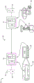
FIG. 1 is a schematic diagram of a data transmission system according to an embodiment;
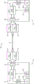
FIG. 2 is a block diagram of a controller in the data transmission system depicted in FIG. 1, according to an embodiment;
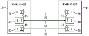
FIG. 3 is a block diagram of a ternary modular redundancy controller according to an embodiment;
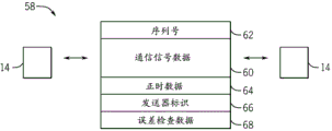
FIG. 4 is a block diagram of a communication signal according to an embodiment;
FIG. 5 is a flow diagram depicting a process to transmit a communication signal to a data transmission system, according to an embodiment;
FIG. 6 is a flow diagram depicting a process to receive a communication signal from a data transmission system, in accordance with an embodiment;
FIG. 7 is a flow diagram depicting a process to detect a fault in a serial link according to an embodiment; and
fig. 8 is a flow diagram depicting a process to detect and correct errors in a received communication signal, in accordance with an embodiment.
Detailed Description
One or more specific embodiments of the present application will be described below. In an effort to provide a concise description of these embodiments, all features of an actual implementation may not be described in the specification. It should be appreciated that in the development of any such actual implementation, as in any engineering or design project, numerous implementation-specific decisions must be made to achieve the developers' specific goals, such as compliance with system-related and business-related constraints, which may vary from one implementation to another. Moreover, it should be appreciated that such a development effort might be complex and time consuming, but would nevertheless be a routine undertaking of design, fabrication, and manufacture for those of ordinary skill having the benefit of this disclosure.
When introducing elements of various embodiments of the present application, the articles "a," "an," "the," and "said" are intended to mean that there are one or more of the elements. The terms "comprising," "including," and "having" are intended to be inclusive and mean that there may be additional elements other than the listed elements.
Data transmission systems are commonly used in systems, such as industrial control systems and automation systems, to facilitate communication between various input/output (I/O) devices within the system. For example, a data transmission system may enable various controllers to communicate data with one another. Generally, the controller interfaces with and controls various devices, such as turbines, generators, compressors, combustors, sensors, pumps, valves, other field devices, and the like. Thus, the data transmitted by the controller may include data collected by the controlled device, control commands, device status, and the like. Due to the nature of the system in which the data transmission system may be used, it would be beneficial to improve the reliability of such data transmission systems.
One technique to improve the reliability of data transmission systems may include the use of various communication protocols, such as object linking and embedding for process control (OPC), Modbus, foundation fieldbus, process fieldbus, and/or BACnet. In general, these communication protocols may use some software supervision and processing. For example, when using an underlying fieldbus, some level of processing may be used to implement the function blocks that transmit and receive data. However, since some I/O devices may not include the desired processing capabilities for such protocols, the present disclosure includes embodiments that improve the reliability of the transmission system of the I/O device regardless of the processing capabilities. Thus, the techniques described herein provide a low-level serial link for communication in various applications, including security system applications. The low-level serial link may use less processing and resources (e.g., software and hardware resources), but provide suitable operation to meet a desired Safety Integrity Level (SIL) certification, including SIL1,2,3, and/or 4. In some embodiments, the low-level serial link may apply a hardware failure detection scheme to provide the desired security authentication, which is adapted to reduce the use of processing and other resources.
Thus, the first embodiment describes a fault tolerant transmission system comprising programmable logic devices. The programmable logic device includes a first serial port communicatively coupled to a first serial link, wherein the first serial port receives a first transmission signal from the first serial link, and a second serial port communicatively coupled to a second serial link, wherein the second serial port receives a second transmission signal from the second serial link. The first and second serial links are arranged in parallel with each other and communicate on a first single conduit, and the first and second communication signals represent the same information. The programmable logic device also includes circuitry that detects a fault in the first serial link, the second serial link, or both by comparing the first communication signal and the second communication signal, and if a fault is detected, determines whether the transmission system can continue to operate despite the fault. In other words, receiving parallel communication signals representing the same information enables detection of a fault in a communication link (e.g., a serial link) between various devices. Furthermore, the transmission system may be more fault tolerant by intelligently reacting to detected faults.
Further, the second embodiment describes a data transmission system including a programmable logic device. The programmable logic device includes a first serial port communicatively coupled to a first serial link, wherein the first serial port receives a first transmission signal from the first serial link, and a second serial port communicatively coupled to a second serial link, wherein the second serial port receives a second transmission signal from the second serial link. The first and second serial links are arranged in parallel with each other and communicate on a single conduit, and the first and second communication signals represent the same information. The programmable logic device also includes circuitry to compare the first communication signal and the second communication signal to detect an error in data included in the first communication signal, the second communication signal, or both, and when the error is detected, correct the error in real-time based at least in part on the comparison of the first communication signal and the second communication signal. In other words, receiving parallel communication signals representing the same information enables detection and real-time correction of errors in the communication signals. As used herein, "real-time" is intended to mean immediately after the previous step. For example, error correction may begin as soon as an error is detected.
As will be described in more detail below, in some embodiments, the data transmission system may use hardware with little or no software supervision to improve the reliability of the transmission system. Thus, improved reliability of the data transfer system may be provided to I/O devices with processors and those without processors. Further, the techniques described herein enable I/O devices to comply with International Electrotechnical Commission (IEC)61508, and in some embodiments, meet SIL1,2,3, and/or 4 certification.
By way of introduction, FIG. 1 depicts an embodiment of a data transmission system 10 disposed in an industrial control system 12. The industrial control system 12 includes a plurality of controllers 14 that can each interface with and control various devices in the industrial control system 12. As depicted, a first controller is coupled to and controls the turbine 16 (e.g., gas turbine, steam turbine, water turbine) and is communicatively coupled to the sensor 18, and a second controller is coupled to and controls the valve 20 and the pump 22. In other embodiments, the controller 14 may be coupled to and control other devices in the industrial control system 12, such as combustors, generators, and other turbines.
Further, as depicted, the controllers 14 may communicate with each other via the data transmission system 10. In some embodiments of the industrial control system 12, the data transmission system 10 may include a High Speed Ethernet (HSE) network or an H1 network. However, as will be described in more detail below, the techniques described herein may use any serial point-to-point architecture. By using the data transmission system 10, the controller 14 can transmit various types of data, such as the state of the connected devices, collected measurement results, and control commands. For example, a first controller may transmit measurements collected by the sensor 18 to a second controller via the data transmission system 10. In response, the second controller may transmit a control command instructing the first controller to modify the operation of the turbine 16. Thus, to facilitate communication, control of connected devices, and other various functions of the controller, the controller 14 includes one or more processors 24 and a memory 26, the memory 26 storing non-transitory machine-readable instructions executable by the one or more processors 24.
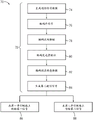
A detailed diagram of an embodiment of the data transmission system 10 is depicted in fig. 2. As depicted, each controller 14 includes a data transmission subsystem 15. In some embodiments, the data transmission subsystem 15 may be a programmable logic device, such as a field programmable gate array, programmable array logic, programmable logic array, general array logic, or any combination thereof. In other embodiments, subsystem 15 may be an application specific integrated circuit. Further, the data transport subsystem 15 may include hardware subsystems (e.g., such as hot-pluggable cards) for each controller 14. One example of a controller 14 that may include a subsystem 15 is the Mark VIe control system available from general electric Company (Schenectady, New York).
In the depicted embodiment, the functions performed by the data transmission subsystem 15 are represented as functional blocks that may be performed by the controller processor 24 and/or the memory 26. As depicted, subsystem 15 includes a clock system (function block 27), a Free Running Counter (FRC) (function block 28), data I/O (function block 30), data compare/copy (function block 32), and parallel I/O ports (function blocks 34 and 36) that couple controller 14 to data transmission system 10. As will be described in more detail below, FRC28 may generate timing data to achieve time synchronization of communication signals; the data I/O30 may generate communication signals; and the data comparison/replication 32 may replicate the communication signal, detect a fault in the communication link (e.g., serial link), and detect/correct errors in the received communication signal.
Further, as depicted, the transmission system 10 includes a single conduit (e.g., cable) 38, and serializer transceivers 40 and 42 coupled to either end of the conduit 38. More specifically, the serial transceivers 40 and 42 interface with the I/ O ports 34 and 36 to enable the controller 14 to communicate with other controllers 14 via the subsystem 15. The serial transceivers 40 and 42 may be RS-232 transceivers, RS-485 transceivers, differential bus transceivers, single-ended transceivers, or other low-level serial transceivers. In some embodiments, only one cable (e.g., Cat 5e, or Cat 6) is used to connect the two subsystems 15, thus minimizing the catheter and associated equipment. In other embodiments, multiple cables may be used. In some embodiments, the serial transceivers 40 and 42 may transmit communication signals at frequencies below the radio frequency to minimize the amount of noise in the signals caused by the radio frequency. For example, the serial transceivers 40 and 42 may be communicated between 1 to 20MHz, 20 to 30MHz, 30 to 40MHz, 40 to 50MHz, 50 to 60MHz, 60 to 100MHz, or any combination thereof, to enable data transmission between 1 to 20 megabits/second, 20 to 30 megabits/second, 30 to 40 megabits/second, 40 to 50 megabits/second, 50 to 60 megabits/second, 60 to 100 megabits/second, or any combination thereof.
Although not explicitly depicted, the single conduit 38 includes a first serial link coupling the serial transceivers 40, and a second serial link coupling the parallel serial transceivers 42. More specifically, the first and second serial links may enable parallel transmission of communication signals between the controllers 14. For example, a first communication signal may be transmitted via a first serial link and a second communication signal may be transmitted in parallel and substantially simultaneously via a second serial link. As will be described in more detail below, the first communication signal and the second communication may represent the same information, which facilitates detection of faults in the serial link and detection/correction of errors in the communication signals. In some embodiments, a suitable conduit 38 may be a category 5 (Cat5) cable because it includes eight serial lines, which enables four lines for the first serial link and four lines for the second serial link. In other embodiments, the first serial link and the second serial link may be included on separate conduits. Furthermore, as depicted, a single conduit 38 couples one controller to another, thus setting up a serial point-to-point architecture. As used herein, a "point-to-point architecture" is intended to describe when one device is directly coupled to another device. In other words, in some embodiments, the controllers 14 may be exclusively transmitted via the conduit 38, which enables both controllers 14 to predetermine (e.g., expect or predict) the identity of the other controller 14, the time of transmission of the communication signals, the order of the communication signals, or any combination thereof. Such architectures may be suitable for communication between devices positioned 1 to 10 meters apart, 10 to 20 meters apart, 20 to 30 meters apart, 30 to 40 meters apart, 40 to 100 meters apart, or any combination thereof.
In some embodiments, the controller 14 may be a Triple Modular Redundant (TMR) controller 14 as depicted in fig. 3. In general, the TMR controller 14 can improve reliability by using three cores. More specifically, as depicted, the TMR controller 14 includes an R core 46, an S core 48, and a T core 50 that all function substantially the same. Thus, the TMR controller 14 operates through a voting scheme to reduce the effect of a failed core (e.g., 46, 48, or 50).
As depicted, the R-core 46 in the TMR controller 14 is coupled by a first transmission system 52, the S-core 48 is coupled by a second transmission system 54, and the T-core is coupled by a third transmission system 56. More specifically, in some embodiments, each of the transmission systems (e.g., 52, 54, and 56) may function similar to the data transmission system 10 described above, e.g., by including the data transmission subsystem 15 and operating substantially independently of one another. More specifically, each transmission system (e.g., 52, 54, and 56) may include a first serial link and a second serial link (or any other component of subsystem 15) to enable parallel transmission of communication signals between pairs of cores. In other words, the first transmission system 52 may transmit parallel communication signals (e.g., two or more identical data transmissions) between the R-cores 46, the second transmission system 54 may transmit parallel communication signals between the S-cores 48, and the third transmission system 56 may transmit parallel communication signals between the T-cores 50. Further, as described above, the first and second serial links may be included in a single or two separate conduits. Thus, in the embodiment depicted in FIG. 3, three separate conduits or six separate conduits may be used. Alternatively, all six serial links may be included in a single conduit.
An embodiment of a communication signal 58 that may be transmitted between controllers 14 via data transmission system 10 is depicted in fig. 4. As depicted, communication signal 58 includes communication signal data 60, serial number 62, timing data 63, transmitter identification 66, and error checking data 68. The communication signal data 60 may include data intended for transmission between the controllers 14. For example, the communication signal data 60 may include control commands, registration data, authentication data, voting data, measurement data, device status, and the like.
The sequence number 62 may represent the order in which the communication signal 58 is transmitted. In some embodiments, the sequence number 62 may be included in a header of the communication signal 58. Thus, the sequence number 58 may enable the receiving controller 14 to determine the order in which the communication signals 58 are transmitted.
As described above, timing data 64 may be generated by FRC28 to achieve time synchronization of communication signal 58. For example, in some embodiments, timing data 64 may be a unique character representing a count in FRC 28. Thus, if FRC28 in transmit and receive controllers 14 is synchronized, timing data 64 enables receive controllers 14 to determine when to transmit communication signal 58.
The transmitter identification 66 may identify the transmission controller 14. For example, in some embodiments, the sender identification may be a Media Access Control (MAC) address, a proprietary unique module identification code, or other similar unique identifier. In some embodiments, the proprietary unique module identification code may include a unique serial number that includes a date code. Thus, the sender identification 66 may enable the receiving controller 14 to determine the identity of the transmitting controller 14.
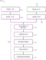
As described above, the transmission system 10 enables communication signals 58 to be transmitted between the controllers 14. Fig. 5 depicts an embodiment of a process 70 that may be used by the transmit controller 14, and more particularly the data transmission subsystem 15 (e.g., a programmable logic device), to transmit parallel communication signals. Process 70 may be implemented by non-transitory computer readable instructions or code stored in memory 26 and executed by processor 24. In the depicted embodiment, the process 70 begins by generating a first communication signal (bracket 72) that includes generating communication signal data (process block 74), an encoded serial number (process block 76), encoded timing data (process block 78), an encoded transmitter identification (process block 80), and encoded error data (process block 82). The process 70 continues by generating a second communication signal (process block 84), and transmitting the first communication signal over the first serial link (process block 86), and transmitting the second communication signal over the parallel second serial link (process block 88).
More specifically, the first communication signal may be generated by the data I/O30. To generate communication signal data 60 (process block 74), data I/O30 may focus data transmitted on the first communication signal. For example, when the device status is to be transmitted, the data I/O30 may query the connected device (e.g., 16, 20, or 22) for its status or retrieve measurements from sensors (e.g., 18) monitoring the device. To encode the sequence number 62 (process block 76), the data I/O30 may include a sequence counter that is incremented with each communication signal transmitted. Thus, the count from the counter may include a sequence number 62 that is representative of the order of the transmitted communication signals 58. To encode the sender identification 66 (process block 80), the data I/O30 may retrieve from the memory 26 of the transferring controller a stored unique identifier identifying the transferring controller.
To encode the timing data 64 (process block 78), the data I/O30 may receive the timing data 64 from the FRC 28. More specifically, FRC28 may generate timing data 64 based on a timing signal received from system clock 27. For example, FRC28 may count based on a timing signal and reset the count once it reaches a certain number. Based on the count at which the communication signal 58 is to be transmitted, FRC28 may output a unique character representing the count. Thus, when communication signal 58 is received, the receiving controller may compare the unique character to the count in its own FRC28 to determine when communication signal 58 is transmitted.
To encode the error-checking data 68 (process block 82), the data I/O30 may perform data checking methods, such as a cyclic redundancy check, a checksum, a cryptographic hash function, and so forth. For example, when using cyclic redundancy checking, the data I/O30 may perform a polynomial division on the communication signal 58, or more specifically the communication signal data 60, and encode the remainder of the division as error check data 68. Thus, the receiving controller 14 may detect errors by repeating the error checking technique and matching the results to the error check data 68. In other embodiments, the encoded serial number 62 (process block 76), the encoded timing data 64 (process block 76), the encoded transmitter identification 66 (process block 76), and the encoded error check data 68 (process block 76) may be performed in any order.
The first communication signal may then be passed from the data I/O30 to the data compare/copy 32 to generate a second communication signal (process block 84). More specifically, the data comparison/duplication 32 may generate a second communication signal to represent the same information as the first communication signal, for example, by duplicating the first communication signal. Additionally or alternatively, to generate the second communication signal, the data compare/copy 32 may convert the first communication signal (e.g., change a "1" to a "0" and vice versa) or reverse the first communication signal (e.g., change the most significant bits of the first communication signal to the least significant bits of the second communication signal, etc.). For example, if the first communication signal is "10011100," the opposite second communication signal may be "00111001," and the converted second signal may be "01100011.
Reversing and/or inverting the first communication signal may facilitate detecting a fault in the serial link and/or detecting/correcting errors in the transmitted data. For example, when inverting communication signals, if bits in the first communication signal and the second communication signal are both "high" or both "low", an error in one of the communication signals may be detected. Further, when the second communication signal is inverted, an error may be detected if the most significant bits of the first communication signal do not match the least significant bits of the second communication signal. Further, errors may be corrected by replacing erroneous bits on the first communication signal with non-erroneous bits from the second communication signal.
The first communication signal may be transmitted from the data compare/copy 32 to the first I/O port 34 to be transmitted via the first serial link (process block 86), and the second communication signal may be transmitted from the data compare/copy 32 to the second I/O port 36 via the second serial link (process block 88). As will be described in greater detail below, to facilitate serial link failure detection and data error detection/correction, the first communication signal and the second communication signal may be transmitted in parallel and substantially simultaneously.
On the receive side of the transmission system 10, the transmitted communication signal 58 is received by the receive controller 14. Fig. 6 depicts an embodiment of a process 90 that may be used by the receiving controller 14, and more particularly the data transmission subsystem 15 (e.g., a programmable logic device), to receive the parallel communication signals 58 on, for example, a single conduit (e.g., a Cat5 cable). Process 90 may be implemented by non-transitory computer readable instructions or code stored in memory 26 and executed by processor 24. As depicted, the process 90 begins by waiting for a first communication signal (process block 92) and waiting for a second communication signal (process block 94). If a first communication signal is received (process block 96) and a second communication signal is received (process block 98), comparing the first communication signal to the second communication signal (bracket 100), which may include comparing the first communication signal to the second communication signal for a bitwise protocol (process block 102), comparing the encoded sequence number (process block 104), comparing the encoded timing data (process block 106), comparing the transmitter identification (process block 108), and comparing the encoded error checking data (process block 110).
More specifically, the data comparison/duplication 32 may wait to receive a first communication signal via the first I/O port 34 (process block 92) and a second communication signal via the second I/O port 36 (process block 94). In some embodiments, this may include a break in surveillance using communication signals 58 for a rule plan. In other words, the data comparison/duplication 32 may wait a predetermined amount of time, such an expected arrival time for the planned communication signal 58, and the data comparison/duplication signal 58 may output a pause signal if the communication signal 58 is not received within a certain amount of time. In some embodiments, the expected arrival time may be predetermined by the receiving controller 14 because, as described above, using a point-to-point architecture may enable the controller 14 to view the actual arrival time of the previous communication signal 58. Thus, as depicted in FIG. 2, data compare/copy 32 is coupled to clock system 27 to receive a timing signal. In some embodiments, the communication signal 58 is expected every 1 to 5 milliseconds, 5 to 8 milliseconds, 8 to 10 milliseconds, 10 to 12 milliseconds, 12 to 15 milliseconds, 15 to 30 milliseconds, or any combination thereof. Thus, the output of the pause signal may indicate that the communication signal 58 is deleted or delayed.
Upon receiving both the first communication signal and the second communication signal, the data comparison/duplication 32 may begin comparing the first communication signal and the second communication signal (bracket 100), which may facilitate detection of faults in the serial link and detection/correction of errors in the transmitted data. More specifically, to compare the first communication signal and the second communication signal for the bitwise protocol (process block 102), the data comparison/duplication 32 may invert or invert the second communication signal prior to comparing the second communication signal to the first communication signal, as the second communication signal may be an inverted or inverted version of the first communication signal, as described above. Thus, the bit-by-bit comparison may indicate that a bit in the communication signal 58 has been deleted, inserted, or misused. Furthermore, as will be described in greater detail below, the bit-by-bit comparison may facilitate real-time correction of bits in the communication signal 58.
To compare the encoded serial numbers 62 (process block 104), the data comparison/duplication 32 may retrieve the serial numbers 62 from the header of the communication signals 58, which enables the controller 14 to determine the order in which the communication signals 58 are transmitted. More specifically, the data comparison/duplication 32 may compare the serial number 62 encoded on one or both of the first communication signal and the second communication signal with the expected serial number 62. For example, if the serial number 62 encoded on the communication signal 58 is the same as the previous pair of communication signals, a repetition error may be detected. In addition, if the sequence number 62 encoded on the communication signal 58 differs from the expected sequence number, an erasure, insertion, or reordering error may be detected. In some embodiments, as described above, using a point-to-point serial architecture may enable the receiving controller 14 to maintain an expected sequence number because if there is no error, the sequence number 62 encoded on each received communication signal 58 will have a predetermined relationship with the sequence number 62 encoded on the previously received communication signal 58. Thus, comparing the sequence numbers 62 may indicate that one or both of the communication signals 58 are repeated, deleted, inserted, or reordered.
To compare the encoded timing data 64 (process block 106), the data comparison/duplication 32 may time synchronize one or both of the first communication signal and the second communication signal. In some embodiments, this may include determining the time at which communication signal 58 was transmitted by matching timing data 64 encoded on communication signal 58 with stored timing data 64 in memory 26 generated by FRC28 on receiving controller 14. For example, the FRC28 on both the transmit and receive controllers may generate a unique character "X" to indicate 3:00 pm. Further, if the timing data 64 encoded on the communication signal 58 is the same as the timing data 64 encoded on the previously received communication signal 58, a repetition error may be detected. Further, a rearrangement or delay error may be detected if the timing data encoded on the communication signal 58 is earlier than the timing data 64 encoded on the previously received communication signal 58. Thus, comparing the encoded timing data 64 may indicate that one or both of the communication signals 58 are repeated, reordered, or delayed.
To compare the transmitter identifications 66 (process block 108), the data compare/reset 32 may determine the identity of the transmit controller 14. More specifically, this may include matching the transmitter identification 66 encoded on one or both of the first communication signal and the second communication signal with the transmitter identification 66 stored in the memory 26. For example, the controller memory 26 may store a series of transmitter identifications 66 that correspond to the devices from which the controller expects to receive the communication signals 58. In some embodiments, as described above, using a point-to-point serial architecture may enable receiving controller 14 to predetermine which devices controller 14 is coupled to, and store transmitter identifications associated with those devices. Thus, if the encoded transmitter identification 66 corresponds to a device from which the controller 14 did not expect to receive the communication signal 58, comparing the encoded transmitter identification 66 may indicate one or both of the inserted communication signals 58.
To compare the encoded error check data 68 (process block 110), the data comparison/duplication 32 may perform an error check technique, such as a Cyclic Redundancy Check (CRC), on one or both of the first communication signal and the second communication signal to determine whether the received communication signal 58 is being misused. More specifically, the data comparison/replication 32 may replicate the error checking technique performed in the transmit controller 14 and compare the results thereof to the encoded error checking data 68. Thus, comparing the encoded error check data 68 may indicate that one or both of the communication signals 58 are misused or otherwise not matched with each other.
In other embodiments, comparing the communication signals bit by bit (process block 102), comparing the encoded serial number 62 (process block 104), comparing the encoded timing data 64 (process block 106), comparing the transmitter identification 66 (process block 108), and comparing the error check data 68 (process block 110) may be performed in any order. Further, in some embodiments, detection of an insertion, deletion, delay, or any combination thereof may indicate spoofing. As used herein, masquerading is intended to describe unauthenticated intrusions into the transmission system 10. For example, when a communication signal 58 is inserted, deleted, or delayed, this may indicate that an unauthenticated device (e.g., controller 14) is accessing transmission system 10 and altering communication signal 58.
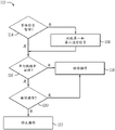
As described above, transmitting first and second communication signals representing substantially identical information in parallel via first and second serial links, respectively, enables detecting faults and/or spoofing in the first serial link, the second serial link, or both. One embodiment of a process 112 that may be used to detect a fault in a serial link is depicted in FIG. 7. The process 112 may be implemented by non-transitory computer readable instructions or code stored in the memory 26 and executed by the processor 24. As depicted, the process 112 may begin by waiting for a first communication signal and a second communication signal (decision block 114). If two communication signals are received, the first communication signal and the second communication signal may be compared (process block 100). Based on the comparison of whether the suspend signal and/or the communication signal are output, a fault in the serial link may be detected (decision block 116). If a failure in the serial link is not detected, the transmission system 10 continues operation (process block 118). On the other hand, if a failure is detected, it may be determined (decision block 120) whether the transmission system 10 should continue to operate regardless of the detected failure (process block 118) or to cease operation (process block 122).
More specifically, as described above, the data comparison/duplication 32 may wait a specified amount of time for the communication signal 58 (process block 114), such as a communication signal frame. If one or both of the communication signals 58 are not received, the data comparison/duplication 32 may output a pause signal indicating that one or both of the communication signals 58 are paused. On the other hand, if two signals 58 are received within a specified amount of time, the data comparison/duplication 32 may compare the communication signals 58 (process block 100), which may include comparing the first and second communication signals 58 for the bitwise protocol (process block 102), comparing the encoded sequence numbers (process block 104), comparing the encoded timing data (process block 106), comparing the transmitter identifications (process block 108), and comparing the encoded error checking data (process block 110). As described above, comparing the communication signals may facilitate detection of errors in data transmitted in the communication signals.
Based on the comparison of the communication signals 58 and/or whether a pause signal is output, the data compare/copy 32 may determine whether a fault exists in the first serial link, the second serial link, or both (decision block 116). For example, if the first communication signal is paused, but the second communication signal is not paused, the data compare/copy 32 may determine that the first serial link has a failure. Further, any error (e.g., duplicate, delete, insert, reorder, misuse, delay, or spoof) may indicate a failure in one or more of the serial links. For example, misuse of the first communication signal 58 but not the second communication signal 58 may indicate that the insulation on the first serial link is weakened and susceptible to external interference, such as stray electromagnetic waves.
Further, in some embodiments, when a failure in the serial link is detected, the state of the serial link may be updated based on the failure. For example, the states of the first and second serial links are set to "good" before a failure is detected, but when a failure in the first serial link is detected, the state of the first serial link may be updated to "failed". As will be described further below, in other embodiments, the states may include intermediate states to enable the transmission system 10 to more intelligently manage operations. For example, a serial link may have a "partial failure" or "potential failure" status if only a single error is detected or if only errors are detected periodically (e.g., not in each transmitted communication signal). For example, the state may be updated from "active" to "latent fault" when a first error is detected, and the state may be updated again to "fault" when a second error, followed by three communication signals, is detected.
If a failure is detected, the data comparison/replication 32 may more intelligently determine whether to stop or continue operation of the transmission system based on the situation associated with the failure (decision block 120). In other words, the transmission system 10 may become more fault tolerant and not shut down immediately whenever a fault in the serial link is detected. In some embodiments, the decision whether to continue operation may depend on the status of the serial link and the information included in the communication signal 58. For example, if the first serial link is "active" but the second serial link is "failed," and the communication signal 58 transmits only temperature measurements, the transmission system 10 may continue to operate based only on the communication signal 58 received via the first serial link. In such embodiments, the controller 14 may decide to continue transmitting and receiving sensor 18 measurements, but may decide to stop the transmission/reception of control commands.
In addition, other factors that affect the decision whether to continue operation of the transmission system 10 may include the nature of the system in which the transmission system 10 is used, as well as the history of errors in the communication signal. For example, the transmission system 10 in a candy manufacturing plant may be more fault tolerant than a nuclear power plant and selected to operate with one "live" serial link and one "latent fault" link, whereas a nuclear power plant may operate with only two "live" serial links. Further, if there is no history of errors, the transmission system 10 may attribute the error to an anomaly and continue operation until a subsequent error is detected. In such embodiments, the transmission system 10 may decide to continue operation for a set period of time to give the operator the opportunity to correct the failed serial link, but to stop operation if the failure is not corrected after the set period of time.
Further, the decision whether to continue operation may depend on whether the error can be corrected in real time. For example, if the error is a deletion or misuse of the most significant bits on both communication signals 58 and the communication signals are reversed, the transmission system 10 may choose to continue operation based on the corrected communication signals 58. The correctability of errors in communication signal 58 will be described in more detail below.
Based on the examples described above, it should be appreciated that the decision whether to continue or stop operation may be customized based on one or more of a variety of factors, such as the nature of the system using transmission system 10, the status of the serial link, whether errors in communication signal 58 can be corrected in real time, the nature of the information transmitted in communication signal 58, the history of errors, and so forth. The functions used for such determinations may be performed by data comparison/replication 32, or other systems of processor 24 and/or memory 26.
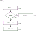
One embodiment of a process 124 for correcting errors in real-time is depicted in FIG. 8. Process 124 may be implemented by non-transitory machine readable instructions or code stored in memory 26 and executed by processor 24. As depicted, when an error is detected (process block 126), a determination is made as to whether the error is correctable (decision block 128). If the error is not correctable, the transmission system 10 may stop operation (process block 132). If it is correctable, the error is corrected in real time (process block 134) and the transmission system 10 continues to operate (process block 136).
More specifically, the data comparison/replication 32 may determine whether the error can be corrected based on various factors, such as the type of error and the size of the error. For example, in the example described above, if the error is simply the most significant bit of the respective communication signal 58 being misused and the communication signals 58 reversed, the data comparison/duplication 32 may correct the error by replacing the most significant bit on the first communication signal with the least significant bit on the second communication signal and vice versa. Furthermore, if the detected error is repeated, the transmission system 10 can simply correct the error by performing early reception of the communication signal and regardless of subsequent reception. Similarly, if the detected error is an insertion, the transmission system may simply correct the error regardless of the inserted communication signal 58. On the other hand, if the detected error is camouflaged, the error may not be correctable and the transmission system 10 may choose to cease operation because an intrusion into the transmission system 10 has been detected.
Based on the above example, the data comparison/duplication 32 may correct errors affecting one or more bits of the first communication signal in real-time by replacing erroneous bits in the first communication signal with non-erroneous bits from the second communication signal. Further, the data comparison/duplication 32 may correct errors that affect the first communication signal but do not affect the second communication signal by being in spite of the first communication signal. Further, the data comparison/duplication 32 may correct for errors affecting both the first communication signal and the second communication signal by either. It will be appreciated that the correctability of detected errors may be fact-specific. The functions for such determinations may be performed by the data comparison/replication 32 or other portions of the processor 24 and/or memory 26.
Further, the techniques described herein enable correcting errors in real time or once errors are detected. For example, in the example described above, the most significant bits of the first communication signal may be replaced by the least significant bits of the second communication signal (as they are compared bit-by-bit), the earlier received communication signal 58 may be performed upon receipt, and the subsequently received communication signal may be disregarded upon receipt, and the inserted communication signal 58 may be disregarded upon receipt.
Although the above description describes two serializer links, other embodiments may include more than two serializer links (e.g., three or four serializer links). As can be appreciated, the use of more than two parallel-serial links may generally improve the reliability of the data transmission system 10 using the techniques described above.
Technical effects of the described embodiments include improving the reliability of the data transmission system 10. More specifically, the reliability of the data transmission system 10 may be improved by using parallel-serial links that each transmit in parallel communication signals 58 representing the same information. Based on the receipt and comparison of the parallel communication signal 58, faults in the serial link and errors in the communication signal may be detected. Thus, the reliability of the transmission system 10 may be improved by making the transmission system 10 more fault tolerant and correcting errors in real time. Furthermore, in some embodiments, the detection and/or correction of faults and errors may be provided using hardware only, which enables improved reliability to be provided to all devices regardless of processing power.
This written description uses examples to disclose the invention, including the best mode, and also to enable any person skilled in the art to practice the invention, including making and using any devices or systems and performing any incorporated methods. The patentable scope of the invention is defined by the claims, and may include other examples that occur to those skilled in the art. Such other examples are intended to be within the scope of the claims if they have structural elements that do not differ from the literal language of the claims, or if they include equivalent structural elements with insubstantial differences from the literal languages of the claims.
Claims (18)
1. A fault tolerant transmission system comprising:
a programmable logic device, comprising:
a first serial port configured to communicatively couple to a first serial link, wherein the first serial port is configured to receive a first communication signal from the first serial link;
a second serial port configured to communicatively couple to a second serial link, wherein the second serial port is configured to receive a second communication signal from the second serial link, wherein the first serial link and the second serial link are disposed in parallel with each other and are configured to communicate on a first single conduit, and the first communication signal and the second communication signal represent the same information; and
a circuit configured to:
detecting a fault in the first serial link, the second serial link, or both by comparing the first communication signal and the second communication signal; and
if a failure is detected, determining whether the transmission system can continue to operate despite the failure;
wherein the circuitry is configured to detect an error in the first communication signal, the second communication signal, or both, and determine whether the transmission system is continuable based at least in part on a property of a system in which the transmission system is used, a state of the serial link, whether the error is correctable in real time, a property of information transmitted in the communication signals, or any combination thereof.
2. The fault tolerant transmission system of claim 1 wherein said programmable logic device is a Ternary Modular Redundant (TMR) controller comprising:
a third serial port configured to communicatively couple to a third serial link, wherein the third serial port is configured to receive a third communication signal from the third serial link;
a fourth serial port configured to communicatively couple to a fourth serial link, wherein the fourth serial port is configured to receive a fourth communication signal from the fourth serial link, wherein the third serial link and the fourth serial link are disposed in parallel with each other and are configured to communicate on a second single conduit, and the third communication signal and the fourth communication signal represent the same information;
a fifth serial port configured to communicatively couple to a fifth serial link, wherein the fifth serial port is configured to receive a fifth communication signal from the fifth serial link;
a sixth serial port configured to communicatively couple to a sixth serial link, wherein the sixth serial port is configured to receive a sixth communication signal from the sixth serial link, wherein the fifth serial link and the sixth serial link are disposed in parallel with each other and are configured to communicate on a third single conduit, and the fifth communication signal and the sixth communication signal represent the same information;
wherein the circuitry is configured to detect a failure in the third serial link, the fourth serial link, the fifth serial link, the sixth serial link, or any combination thereof.
3. The fault-tolerant transmission system of claim 1, wherein the circuitry is configured to detect duplicates, deletions, insertions, rearrangements, misuse, delays, spoofing, or any combination thereof in the first communication signal, the second communication signal, or both.
4. The fault-tolerant transmission system of claim 1, wherein the circuitry comprises a field programmable gate array, programmable array logic, programmable logic array, general purpose array logic, application specific integrated circuit, or any combination thereof.
5. The fault tolerant transmission system of claim 1 wherein the circuit is configured to:
providing a suspend signal if the first communication signal or the second communication signal is not received within a predetermined amount of time;
checking a bitwise protocol between the first communication signal and the second communication signal;
comparing a serial number encoded on the first communication signal or the second communication signal to an expected serial number stored in the programmable logic device;
comparing timing data encoded on the first communication signal or the second communication signal to stored timing data in the programmable logic device;
comparing the transmitter identification encoded on the first communication signal or the second communication signal with an expected transmitter identification stored in the programmable logic device;
performing an error checking technique on the first communication signal or the second communication signal and comparing a result of the error checking technique with error checking data encoded on the first communication signal or the second communication signal; or
Any combination thereof.
6. A method for using a hardware failure detection system in a transmission system, comprising:
receiving a first communication signal on a first programmable logic device from a second programmable logic device via a first serial link;
receiving a second communication signal on the first programmable logic device from the second programmable logic device via a second serial link, wherein the first serial link and the second serial link are parallel-serial links disposed on a single conduit, and the first communication signal and the second communication signal represent the same information;
comparing the first communication signal and the second communication signal in the first programmable logic device to detect a fault in the first serial link, the second serial link, or both; and
when a failure is detected, determining whether the transmission system can continue to operate despite the failure;
wherein comparing the first communication signal and the second communication signal comprises detecting an error in the first communication signal, the second communication signal, or both, and wherein determining whether the transmission system can continue to operate regardless of the fault is based at least in part on a property of a system using the transmission system, a state of the serial link, whether the error is correctable in real time, a property of information transmitted in the communication signals, or any combination thereof.
7. The method of claim 6, wherein comparing the first communication signal and the second communication signal comprises detecting duplication, deletion, insertion, rearrangement, misuse, delay, spoofing, or any combination thereof in the first communication signal, the second communication signal, or both.
8. The method of claim 6, wherein comparing the first communication signal and the second communication signal comprises checking a bitwise protocol between the first communication signal and the second communication signal.
9. The method of claim 8, wherein checking the bitwise protocol between the first communication signal and the second communication signal comprises translating or inverting the second communication signal.
10. The method of claim 6, comprising waiting a predefined amount of time for the first communication signal and the second communication signal, and outputting a pause signal if the first communication signal or the second communication signal is not received within the predefined amount of time.
11. The method of claim 6, wherein comparing the first communication signal and the second communication signal comprises comparing first timing data encoded on the first communication signal or the second communication signal with second timing data stored in the first programmable logic device.
12. The method of claim 6, wherein comparing the first communication signal and the second communication signal comprises comparing a serial number encoded on the first communication signal or the second communication signal to an expected serial number stored in the first programmable logic device.
13. The method of claim 6, wherein comparing the first communication signal and the second communication signal comprises comparing a transmitter identification encoded on the first communication signal or the second communication signal to an expected transmitter identification stored in the first programmable logic device.
14. The method of claim 6, wherein comparing the first communication signal and the second communication signal comprises:
performing an error checking technique on the first communication signal or the second communication signal; and
comparing results of the error checking technique to error checking data encoded on the first communication signal or the second communication signal.
15. The method of claim 14, wherein the error checking technique comprises a cyclic redundancy check.
16. The method of claim 6, wherein the comparing the first communication signal and the second communication signal is performed using only hardware without software supervision.
17. The method of claim 6, wherein the single conduit comprises a cable having a first line and a second line, wherein the first line comprises the first serial link and the second line comprises the second serial link.
18. A method for operating a fault tolerant transmission system, comprising:
detecting a fault in a first serial link, a second serial link, or both by detecting an error in a first communication signal transmitted over the first serial link or a second communication signal transmitted over the second serial link using only hardware detection in the first programmable logic device, wherein the first communication signal and the second communication signal are transmitted from the second programmable logic device to the first programmable logic device in parallel and represent the same information;
when a fault is detected, determining a status of the first serial link, the second serial link, or both based at least in part on the detected error; and
determining whether to continue operating the transmission system based at least in part on a status of the first serial link, the second serial link, or both;
wherein circuitry is configured to detect an error in the first communication signal, the second communication signal, or both, and determine whether the transmission system is continuable based at least in part on a property of a system in which the transmission system is used, a state of the serial link, whether the error is correctable in real time, a property of information transmitted in the communication signals, or any combination thereof.
Applications Claiming Priority (2)
| Application Number | Priority Date | Filing Date | Title |
|---|---|---|---|
| US14/145,459 US9178757B2 (en) | 2013-12-31 | 2013-12-31 | Serial link fault detection system and method |
| US14/145459 | 2013-12-31 |
Publications (2)
| Publication Number | Publication Date |
|---|---|
| CN104750566A CN104750566A (en) | 2015-07-01 |
| CN104750566B true CN104750566B (en) | 2020-01-10 |
Family
ID=52282441
Family Applications (1)
| Application Number | Title | Priority Date | Filing Date |
|---|---|---|---|
| CN201410845706.8A Active CN104750566B (en) | 2013-12-31 | 2014-12-31 | Serial link fault detection system and method |
Country Status (5)
| Country | Link |
|---|---|
| US (1) | US9178757B2 (en) |
| EP (1) | EP2889772B1 (en) |
| JP (1) | JP6648966B2 (en) |
| CN (1) | CN104750566B (en) |
| AU (1) | AU2014274576B2 (en) |
Families Citing this family (8)
| Publication number | Priority date | Publication date | Assignee | Title |
|---|---|---|---|---|
| FR3024932B1 (en) * | 2014-08-14 | 2017-12-01 | Sagem Defense Securite | METHOD FOR TRANSMITTING DATA WITH IMPROVED ROBUSTNESS AND SET OF DEVICES FOR IMPLEMENTING IT |
| US10012213B2 (en) * | 2016-02-04 | 2018-07-03 | General Electric Company | System and method for upgrading multivendor wind turbines |
| CN107220137B (en) * | 2017-05-24 | 2020-05-26 | 苏州浪潮智能科技有限公司 | CPLD-based serial port signal detection method, device and system |
| WO2019140005A1 (en) * | 2018-01-09 | 2019-07-18 | TuSimple | Real-time remote control of vehicles with high redundancy |
| JP7052386B2 (en) * | 2018-02-01 | 2022-04-12 | 富士通株式会社 | Transfer device and transfer method |
| US20190286537A1 (en) * | 2018-03-13 | 2019-09-19 | Carrier Corporation | Detection of wiring faults in serial bus connected components |
| CN109633370B (en) * | 2018-12-08 | 2021-04-23 | 国网山东省电力公司德州供电公司 | Power grid fault diagnosis method based on fault information coding and fusion method |
| EP4354772A1 (en) * | 2022-10-11 | 2024-04-17 | Nxp B.V. | Network device, communication system and method for the network device |
Citations (4)
| Publication number | Priority date | Publication date | Assignee | Title |
|---|---|---|---|---|
| US4750177A (en) * | 1981-10-01 | 1988-06-07 | Stratus Computer, Inc. | Digital data processor apparatus with pipelined fault tolerant bus protocol |
| US5784383A (en) * | 1997-10-02 | 1998-07-21 | International Business Machines Corporation | Apparatus for identifying SMP bus transfer errors |
| US5832279A (en) * | 1995-06-07 | 1998-11-03 | Lsi Logic Corporation | Advanced programmable interrupt controller (APIC) with high speed serial data bus |
| CN103404066A (en) * | 2011-04-22 | 2013-11-20 | 三菱电机株式会社 | Communication device using plurality of communication paths |
Family Cites Families (24)
| Publication number | Priority date | Publication date | Assignee | Title |
|---|---|---|---|---|
| DE2420166A1 (en) | 1974-04-25 | 1975-11-13 | Siemens Ag | Electrical machine angular displacement sensor - has two probes using Hall generators or inductive coils with differential amplifiers and pulse former |
| JPS5742244A (en) * | 1980-08-28 | 1982-03-09 | Fujitsu Ltd | Optical transmission system |
| US4633473A (en) * | 1984-08-02 | 1986-12-30 | United Technologies Corporation | Fault tolerant communications interface |
| US4689546A (en) | 1985-12-18 | 1987-08-25 | General Electric Company | Internal armature current monitoring in large three-phase generator |
| JPS6331241A (en) * | 1986-07-25 | 1988-02-09 | Nec Corp | Switch signal transfer system |
| US6397157B1 (en) | 1999-07-02 | 2002-05-28 | General Electric Company | Method and apparatus for real time measurement of three phase electrical parameters |
| FR2814089B1 (en) | 2000-09-21 | 2003-07-04 | Ethypharm Lab Prod Ethiques | PROCESS FOR ISOLATING AND DRYING MICROPARTICLES (MICROSPHERES OR MICROCAPSULES) INITIALLY DISPERSED OR SUSPENDED IN THE LIQUID PHASE |
| US6879922B2 (en) | 2001-09-19 | 2005-04-12 | General Electric Company | Systems and methods for suppressing pressure waves using corrective signal |
| US20050035768A1 (en) | 2002-10-02 | 2005-02-17 | Germano Rabach | Method and electromagnetic sensor for measuring partial discharges in windings of electrical devices |
| WO2004099800A2 (en) | 2003-05-09 | 2004-11-18 | Siemens Aktiengesellschaft | Measuring device, and method for locating a partial discharge |
| JP4468795B2 (en) * | 2004-12-02 | 2010-05-26 | 株式会社 エニイワイヤ | Control / monitor signal transmission system, electronic equipment |
| JP4498973B2 (en) * | 2005-05-11 | 2010-07-07 | 株式会社日立製作所 | Wireless communication apparatus, wireless communication apparatus control method, and program |
| US7343744B2 (en) | 2005-07-27 | 2008-03-18 | General Electric Company | Method and system for controlling a reheat turbine-generator |
| US7642748B2 (en) | 2005-10-19 | 2010-01-05 | General Electric Company | Battery charging system and method of operating same |
| US8363541B2 (en) * | 2006-12-22 | 2013-01-29 | Pratt & Whitney Canada Corp. | Serial digital communication protocol |
| US20090019396A1 (en) * | 2007-07-11 | 2009-01-15 | Agilent Technologies, Inc. | User Programmable Key in a User Interface System |
| US8117512B2 (en) * | 2008-02-06 | 2012-02-14 | Westinghouse Electric Company Llc | Failure detection and mitigation in logic circuits |
| US7870299B1 (en) * | 2008-02-06 | 2011-01-11 | Westinghouse Electric Co Llc | Advanced logic system |
| TWI416329B (en) * | 2009-01-06 | 2013-11-21 | Starchips Technology Inc | Serially connected transmission apparatus and the method thereof |
| DE102009033241B4 (en) * | 2009-07-14 | 2013-07-04 | Audi Ag | Prevention of masquerade through the use of identification sequences |
| JP5548461B2 (en) * | 2010-01-15 | 2014-07-16 | 株式会社リブ技術研究所 | Communication circuit, communication network, and connecting device |
| JP5394283B2 (en) * | 2010-02-25 | 2014-01-22 | 株式会社日立産機システム | Information processing apparatus and control network system |
| JP5167329B2 (en) * | 2010-11-29 | 2013-03-21 | 株式会社日立製作所 | Wireless communication system for vehicle control |
| JP5804365B2 (en) * | 2011-08-24 | 2015-11-04 | 国立大学法人 大分大学 | Diversity optical transmission apparatus and method |
-
2013
- 2013-12-31 US US14/145,459 patent/US9178757B2/en active Active
-
2014
- 2014-12-11 AU AU2014274576A patent/AU2014274576B2/en not_active Ceased
- 2014-12-18 EP EP14199029.1A patent/EP2889772B1/en active Active
- 2014-12-19 JP JP2014256770A patent/JP6648966B2/en active Active
- 2014-12-31 CN CN201410845706.8A patent/CN104750566B/en active Active
Patent Citations (4)
| Publication number | Priority date | Publication date | Assignee | Title |
|---|---|---|---|---|
| US4750177A (en) * | 1981-10-01 | 1988-06-07 | Stratus Computer, Inc. | Digital data processor apparatus with pipelined fault tolerant bus protocol |
| US5832279A (en) * | 1995-06-07 | 1998-11-03 | Lsi Logic Corporation | Advanced programmable interrupt controller (APIC) with high speed serial data bus |
| US5784383A (en) * | 1997-10-02 | 1998-07-21 | International Business Machines Corporation | Apparatus for identifying SMP bus transfer errors |
| CN103404066A (en) * | 2011-04-22 | 2013-11-20 | 三菱电机株式会社 | Communication device using plurality of communication paths |
Also Published As
| Publication number | Publication date |
|---|---|
| JP6648966B2 (en) | 2020-02-19 |
| EP2889772B1 (en) | 2019-04-24 |
| US9178757B2 (en) | 2015-11-03 |
| CN104750566A (en) | 2015-07-01 |
| US20150188755A1 (en) | 2015-07-02 |
| AU2014274576B2 (en) | 2019-08-01 |
| EP2889772A1 (en) | 2015-07-01 |
| JP2015136104A (en) | 2015-07-27 |
| AU2014274576A1 (en) | 2015-07-16 |
Similar Documents
| Publication | Publication Date | Title |
|---|---|---|
| CN104750566B (en) | Serial link fault detection system and method | |
| US9374194B2 (en) | Transmission system error detection and correction system and method | |
| CN110851392B (en) | Communication method and communication system based on Modbus RTU protocol | |
| US6909923B2 (en) | Safety communication on a single backplane | |
| US8209594B2 (en) | Sending device, receiving device, communication control device, communication system, and communication control method | |
| CN110532117A (en) | For the error checking for the main signal transmitted between the first and second clock domains | |
| EP3979527A1 (en) | System and method of network synchronized time in safety applications | |
| CN109074294A (en) | Communication device and communication system | |
| US7319406B2 (en) | System and method of channel serialization in a safety I/O product | |
| CN101432671B (en) | Safety control device, safety control system, and method for detecting communication error | |
| JP2012235335A (en) | Method and device for detecting incorrect connection between devices | |
| US9641287B2 (en) | Methods and apparatus for high-integrity data transfer with preemptive blocking | |
| JPWO2020090034A1 (en) | Processing equipment | |
| EP2824572B1 (en) | Fail safe device and method for operating the fail safe device | |
| US9230290B2 (en) | Power meter consumption system and method to verify data stored in a register by comparing an address of the register with request for data of the register | |
| EP3507944B1 (en) | Improved voting for profibus line redundancy | |
| JP2006033075A (en) | Serial communications apparatus | |
| JP2014164561A (en) | Control device, control system, and data generation method | |
| Borangiu et al. | ANALYSIS OF THE DATA TRANSMISSION IN THE INDUSTRIAL AUTOMATION SYSTEMS | |
| Ghareaghaji | FPGA Based Controller Area Network | |
| Saha et al. | Analysis of residual errors and their consequences in CANopen systems | |
| Cotton et al. | The Safety Layer: Communications protocol extension for safety related functions | |
| JPS63158931A (en) | Duplicated data receiver | |
| JP2008109324A (en) | Communication system |
Legal Events
| Date | Code | Title | Description |
|---|---|---|---|
| C06 | Publication | ||
| PB01 | Publication | ||
| C10 | Entry into substantive examination | ||
| SE01 | Entry into force of request for substantive examination | ||
| GR01 | Patent grant | ||
| GR01 | Patent grant | ||
| TR01 | Transfer of patent right |
Effective date of registration: 20240110 Address after: Swiss Baden Patentee after: GENERAL ELECTRIC CO. LTD. Address before: New York State, USA Patentee before: General Electric Co. |
|
| TR01 | Transfer of patent right |