CN1045273C - Screw cap and tamper-indicating band, package provided with such a cap, method for the manufacture of said cap and package - Google Patents
Screw cap and tamper-indicating band, package provided with such a cap, method for the manufacture of said cap and package Download PDFInfo
- Publication number
- CN1045273C CN1045273C CN94190833A CN94190833A CN1045273C CN 1045273 C CN1045273 C CN 1045273C CN 94190833 A CN94190833 A CN 94190833A CN 94190833 A CN94190833 A CN 94190833A CN 1045273 C CN1045273 C CN 1045273C
- Authority
- CN
- China
- Prior art keywords
- blind nut
- inner component
- exterior part
- vulnerable areas
- fragility
- Prior art date
- Legal status (The legal status is an assumption and is not a legal conclusion. Google has not performed a legal analysis and makes no representation as to the accuracy of the status listed.)
- Expired - Fee Related
Links
Images


Classifications
-
- B—PERFORMING OPERATIONS; TRANSPORTING
- B65—CONVEYING; PACKING; STORING; HANDLING THIN OR FILAMENTARY MATERIAL
- B65D—CONTAINERS FOR STORAGE OR TRANSPORT OF ARTICLES OR MATERIALS, e.g. BAGS, BARRELS, BOTTLES, BOXES, CANS, CARTONS, CRATES, DRUMS, JARS, TANKS, HOPPERS, FORWARDING CONTAINERS; ACCESSORIES, CLOSURES, OR FITTINGS THEREFOR; PACKAGING ELEMENTS; PACKAGES
- B65D41/00—Caps, e.g. crown caps or crown seals, i.e. members having parts arranged for engagement with the external periphery of a neck or wall defining a pouring opening or discharge aperture; Protective cap-like covers for closure members, e.g. decorative covers of metal foil or paper
- B65D41/32—Caps or cap-like covers with lines of weakness, tearing-strips, tags, or like opening or removal devices, e.g. to facilitate formation of pouring openings
- B65D41/34—Threaded or like caps or cap-like covers provided with tamper elements formed in, or attached to, the closure skirt
- B65D41/3423—Threaded or like caps or cap-like covers provided with tamper elements formed in, or attached to, the closure skirt with flexible tabs, or elements rotated from a non-engaging to an engaging position, formed on the tamper element or in the closure skirt
- B65D41/3428—Threaded or like caps or cap-like covers provided with tamper elements formed in, or attached to, the closure skirt with flexible tabs, or elements rotated from a non-engaging to an engaging position, formed on the tamper element or in the closure skirt the tamper element being integrally connected to the closure by means of bridges
-
- B—PERFORMING OPERATIONS; TRANSPORTING
- B65—CONVEYING; PACKING; STORING; HANDLING THIN OR FILAMENTARY MATERIAL
- B65D—CONTAINERS FOR STORAGE OR TRANSPORT OF ARTICLES OR MATERIALS, e.g. BAGS, BARRELS, BOTTLES, BOXES, CANS, CARTONS, CRATES, DRUMS, JARS, TANKS, HOPPERS, FORWARDING CONTAINERS; ACCESSORIES, CLOSURES, OR FITTINGS THEREFOR; PACKAGING ELEMENTS; PACKAGES
- B65D2401/00—Tamper-indicating means
- B65D2401/15—Tearable part of the closure
- B65D2401/30—Tamper-ring remaining connected to closure after initial removal
-
- B—PERFORMING OPERATIONS; TRANSPORTING
- B65—CONVEYING; PACKING; STORING; HANDLING THIN OR FILAMENTARY MATERIAL
- B65D—CONTAINERS FOR STORAGE OR TRANSPORT OF ARTICLES OR MATERIALS, e.g. BAGS, BARRELS, BOTTLES, BOXES, CANS, CARTONS, CRATES, DRUMS, JARS, TANKS, HOPPERS, FORWARDING CONTAINERS; ACCESSORIES, CLOSURES, OR FITTINGS THEREFOR; PACKAGING ELEMENTS; PACKAGES
- B65D2401/00—Tamper-indicating means
- B65D2401/15—Tearable part of the closure
- B65D2401/35—Vertical or axial lines of weakness
Landscapes
- Engineering & Computer Science (AREA)
- Mechanical Engineering (AREA)
- Closures For Containers (AREA)
- Bag Frames (AREA)
Abstract
Plastic screw cap comprising a closure portion (3), optional sealing means (7) added to or incorporated with the closure portion (3), and a tamper-indicating band (8), which forms a single unit with said closure portion (3). According to the invention, the cap comprises a frangible area (17) in the outer portion (9) which is opened during unscrewing of the cap (1). The frangible area opens into an empty space (18) between the outer part (9) and the skirt (5), the empty space (18) being delimited in the direction of unscrewing of the cap (1) by at least one non-frangible fastener (19), during unscrewing of the cap (1), belonging to the linking means (11). The frangible area (20a) of the outer portion also opens into a frangible area (20a), or into a cut (20b), or into a blend (20c) of the inner portion (10).
Description
What the present invention relates to is the blind nut made from plastic material, and this blind nut comprises the not broken sleeve that is contained on the inner component (or translate be turn-on flag sleeve without authorization), and inner component can be return sleeve inner; By this blind nut and container combination package together; The method of making the method for this blind nut and making this package.
The known blind nut of being made by plastic material comprises:
The cover piece that end is a transverse wall and one link to each other with this cover piece and process threaded skirt section in inside;
Be contained on this cover piece or with any type of containment member of this cover piece all-in-one-piece;
And independent member that matches with above-mentioned cover piece, i.e. not broken sleeve, sleeve itself constitutes exterior part, exterior part is on the extension in skirt section, it is by linking to each other with the skirt section along the separated coupling member of circumference, coupling member is between the hanging edge in exterior part and skirt section, near another edge of exterior part be can be around the attenuation edge of an inner component that himself rotates with respect to exterior part, this inner component is return sleeve inner being drawn towards when the protuberance of end cross wall with the container of this blind nut of use cooperates.
In US-A-4613052, US-A-4352436, the described prior art of US-A-4653657 document, the sleeve that exterior part is promptly not broken and the coupling member in skirt section are made of the fragility bridge, and these bridges just disconnect when covering when turning on.
When backing out blind nut, the fragility bridge fractures, and sleeve separates with cover piece, but this moment, sleeve still was inserted on the vessel port, because the inner component of sleeve tightly suppresses the protuberance of container, so be difficult to take out sleeve from vessel port.
Specifically, US Patent 4,458,821 disclose a kind of bottle cap, and the anti-inner component that tears part of this bottle cap is provided with by even interval and constitutes by flexible link belt bonded assembly thin slice, and this bottle cap must need very big power when opening beginning.
In US Patent 5,129, a kind of bottle cap is disclosed in 530, this bottle cap comprises lid and anti-ly tears circle that the sealing effectiveness of this bottle cap can not be satisfactory.
The object of the present invention is to provide a kind of blind nut of the above-mentioned type, the not broken sleeve of this blind nut can be thrown off vessel port.
The present invention proposes a kind of like this bottle cap, comprising: a cover piece, this cover piece has: end cross wall, one link to each other with this wall and have negative thread the skirt section, install on the described cover piece or with this cover piece all-in-one-piece containment member; With one be the not broken sleeve of independent member with respect to cover piece, this not broken sleeve comprises: an exterior part that is made of sleeve self, this exterior part is arranged on the extension in skirt section, it links to each other with the skirt section by coupling member, coupling member is provided with along the circle spacing between the hanging edge in parts and skirt section outside, near another edge of exterior part is can be around the attenuation edge of the inner component that himself rotates with respect to exterior part, when described blind nut was screwed on the described container, this inner component was positioned at the inside of sleeve, cooperate towards the end cross wall and with the projection of container;
Improvement of the present invention is, the exterior part of described not broken sleeve has a vulnerable areas, an opening of vulnerable areas leads to the space between exterior part and the skirt section, and in described gap, described opening be that the adjacent position of downstream direction is provided with at least one non-brittle joint as described coupling member with respect to the direction of turning on blind nut, vulnerable areas is extended vulnerable areas, otch or the fracture portion that arrives inner component at the opposite sense of above-mentioned opening always in addition, thereby after backing out blind nut, not broken sleeve still keeps linking to each other with cover piece.
The present invention also proposes a kind of blind nut and container combination package together, container material mouth has the outside thread that matches with the blind nut negative thread at the neck near opening part, an annular projection is arranged at the bottom near neck in addition, the inner component of blind nut annular protrusion be pressed against on this projection away from an externally threaded end on, and this inner component tilts with respect to exterior part, and inner component rotates around its thin edges along the direction of throwing off with exterior part in backing out the process of blind nut.
The present invention at first provides a kind of blind nut of the above-mentioned type of being made by plastic material, wherein, when turning on blind nut, the vulnerable areas of not broken sleeve exterior part can make its opening arrive in the space between exterior part and the skirt section on the one hand, and this space (with respect to the direction of turning on blind nut) mobile downstream is subjected to the restriction that at least one belongs to the non-brittle joint of described coupling member; Make vulnerable areas, the otch of opening arrival inner component on the other hand or block portion when turning on blind nut, when backing out blind nut, not broken sleeve keeps linking to each other with cover piece by non-brittle joint like this.
This blind nut can select other be characterised in that: vulnerable areas comprises an attenuation position on corresponding exterior part or inner component.This attenuation position is made of the impression on exterior part or the inner component, for example opens a groove on the outside face of these two parts and/or inside face.Vulnerable areas on the exterior part is along extending towards the general strike opposite with hand of spiral with the direction of blind nut axis tilt.Vulnerable areas on the inner component, otch or the portion of blocking are along extending towards the general strike identical or opposite with hand of spiral with the direction of blind nut axis tilt.The bevelled general strike of weak section or otch and the angle between the blind nut axis are 30 °-80 °, but preferably are at or about 45 °.The weak section otch of inner component or exterior part extends along rectilinear direction substantially.Vulnerable areas on the exterior part with and the substantially perpendicular direction of blind nut axis lead in the space between exterior part and the skirt section, thereby this space is obviously extended.Above-mentioned vulnerable areas has a section at least perpendicular to the blind nut axis, and this section is favouring between two sections of blind nut axis.Non-brittle joint is near the end of exterior part vulnerable areas, and the hanging edge place of exterior part is led in this end.The intensity of non-brittle joint is enough to be unlikely when turning on blind nut and is fractureed, but this intensity neither be very big, so that the user uses enough pulling force that it is fractureed after turning on blind nut.Constitute the portion of blocking of inner component by the space that circumferentially extends on described inner component.Extend along an opening arc in this space of blocking portion, and the radian of arc is 20 °-100 °, but be preferably 30 °-90 °, this space of blocking portion along one with the corresponding set corresponding opening arc of non-brittle joint opening on extend.In two edges that limit by the inner component portion of blocking or the several axial planes that are in blind nut substantially, perhaps internally the part thin edges towards the hanging edge fork of this inner component.Edge that is limited by the inner component portion of blocking and blind nut axis are at 45 or approximate 45 ° angle and tilt.Exterior part is except its vulnerable areas, and the thickness on its all peripheries and the axial height is constant substantially, and this thickness is equal to or less than the thickness in skirt section at the most.The axial height of inner component equals the exterior part axial height at the most, and exterior part covers inner component fully.Particularly inner component extends to half of exterior part axial height approximately.Perhaps opposite, inner component is along the axial height of axially extended height greater than exterior part, this moment exterior part just part cover inner component, this inner component some and skirt section meet at right angles.Inner component axially face substantially triangularity or trapezoidal of cross section.Coupling member only is made of some non-brittle joints, and is perhaps opposite, also can be made of along the fragility bridge that circumference separates some non-brittle joints and some, and when turning on blind nut, these bridges just disconnect.Under first kind of situation, exterior part and inner component have two vulnerable areas at least.The cross section of laterally facing of fragility bridge is generally triangle, near skirt section and exterior part inside face be the leg-of-mutton end, and should the end relative drift angle is towards the outside.Described drift angle falls into slightly inwards with respect to the outside face of skirt section and exterior part.The cross section of axially facing of fragility bridge is generally triangle or trapezoidal, against exterior part be long limit, against the skirt section then is drift angle or minor face.The fragility bridge extends along the general strike of axis.Perhaps, the general strike of fragility bridge extension is with respect to the blind nut axis tilt.This trend is exactly the direction that blind nut is turned on.Blind nut can comprise four, five or six fragility bridges.The non-brittle joint and the first fragility bridge away from, and this first fragility bridge is near being the position of upstream with respect to the direction that blind nut is backed out from arc, the radian of described arc is about 45 °-90 °.The effect of non-brittle bridge is to guarantee its reliable connection when lining rotates with respect to cover piece.Blind nut has an axial support at least, the formation of above-mentioned strut member be from hanging edge begin by on skirt section and/or the exterior part towards the extension projection in exterior part and/or skirt section.This projection is in the space between skirt section and the exterior part.Strut member circumferentially extends with the arc of radian less than 40 °.Two adjacent strut members are separated by a fragility bridge or a non-brittle joint to each other at least.By four fragility bridges at the most two adjacent strut members are separated from each other.Non-brittle joint is away from the first fragility bridge near the upstream.So-called upstream is for the direction of being turned on blind nut by strut member.The radial wall thickness of the strut member in close skirt section equals the thickness in skirt section substantially, and its edge is circular.Strut member occupies about 1/3rd circumference to half in space between skirt section and the outside.Corresponding both sides have a non-brittle joint and another non-brittle joint or a fragility bridge respectively on diameter.Inner component tilts with respect to exterior part, and leaning angle is about 10 °-60 °, is about 20 °-40 ° specifically, particularly is about 30 °, and the hanging edge of inner component is separated with exterior part or skirt section diametrically.
According to first embodiment, this blind nut inner component has only a non-brittle joint and vulnerable areas or an otch or a fracture portion.In this embodiment, four fragility bridges are arranged, they are evenly distributed on half circumference of blind nut, and this half circumference is corresponding with vulnerable areas, otch or the fracture portion of exterior part vulnerable areas and each member of inner component.Each member of inner component is separated by described vulnerable areas, otch or breaking portion.Also have three strut members, wherein two corresponding mutually along diametric(al), the 3rd is then corresponding with non-brittle joint along diametric(al).
According to second embodiment, the blind nut inner component has two non-brittle joints respect to one another on diameter, and also having two is vulnerable areas respect to one another, otch or fracture portion on diameter equally.This embodiment also has six fragility bridges that are in the inner component middle part on diameter relative to one another.And also have four in twos relatively, to each other by bridge or the separated strut member of fragility joint.
According to the 3rd embodiment, blind nut comprises that three is the non-brittle joint of inner component and three vulnerable areas that are similarly 120 ° inner component to each other, otch or fracture portions of 120 ° to each other.In this embodiment, have six to be in inner component middle part, and relative with non-brittle joint be 120 ° fragility bridge to each other.Six is 120 ° strut member to each other in addition.
According to the 4th embodiment, this blind nut comprises the non-brittle joint of four quadrntnts that separate each other.In this embodiment, inner component has the fragility bridge and same four vulnerable areas, otch or the fracture portion that arranges of four quadrntnts that separate each other, perhaps has only vulnerable areas, their quadrntnts that separates each other as non-brittle joint and four inner components of coupling member.
According to the 5th embodiment, the hanging edge of inner component is in the same clinoplane (with respect to reference plane perpendicular to the blind nut axis), and this plane inclination direction is identical with the direction of blind nut screw thread.
According to the 6th embodiment, the hanging edge of inner component is in the mono-clinoplane (with respect to reference plane perpendicular to the blind nut axis), and the direction of tilt on this plane is opposite with the blind nut hand of spiral.
According to the 7th embodiment, the hanging edge of inner component is in and severally is in the plane inclined with respect to a plane with the blind nut axis normal.In this case, inner component can be made the impression of several more or less some projection, and quantity is the amount doesn't matter.
According to the second aspect content, what the present invention relates to is by this blind nut and container combination package together, the material mouth of this package is at the outside thread that has near opening part with the blind nut screw-internal thread fit, near the bottom annular projection is arranged in addition, the inner component of returning from blind nut is pressed against on this projection also locked at the externally threaded other end.
In such package, inner component is with respect to angle of exterior part inclination, so that inner component is rotated around the attenuation edge along the direction that it and exterior part are separated.
According to third aspect content, what the present invention relates to is the method for this blind nut of preparation, it is characterized in that spray inner component when exterior part is prolonged makes inner component rotate around its attenuation edge, so that make it get back to the inside of sleeve then.
According to last aspect content, what the present invention relates to is the method for the above-mentioned package of preparation, and this method is when inner component returns to sleeve inner blind nut to be screwed on the container.
Below in conjunction with accompanying drawing various embodiment is described,, will more be expressly understood the present invention by these descriptions, wherein:
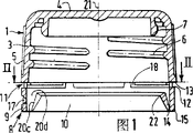
Fig. 1 is the scheme drawing that the blind nut of first embodiment is analysed and observe vertically;
The scheme drawing laterally analysed and observe of Fig. 2 for being done along the II-II line of Fig. 1;
Fig. 3 is the front elevational schematic of the blind nut of first embodiment;
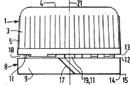
Fig. 4 analyses and observe the partial schematic diagram and partial elevational (right-hand part) scheme drawing of (left side) vertically for the blind nut of second embodiment of the invention;
The scheme drawing of Fig. 5 for laterally analysing and observe along the edge that the V-V line of Fig. 4 is done;
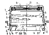
Fig. 6 is the scheme drawing that the blind nut of the 3rd embodiment is analysed and observe vertically;
The scheme drawing of Fig. 7 for laterally analysing and observe along the edge that the VII-VII line of Fig. 6 is done;
Fig. 8 is half front elevation of the blind nut of the 3rd embodiment;
Fig. 9 is the scheme drawing that laterally analyse and observe on the blind nut edge of the 4th embodiment;
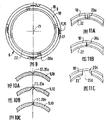
Figure 10 A, 10B, 10C are three width of cloth partial schematic diagrams of the embodiment of the vulnerable areas of expression exterior part or inner component;
Figure 11 A, 11B, 11C are the partial schematic diagram of sleeve inner part, and these charts show brittle zone, otch and block the embodiment of portion;
Figure 12 and 13 is the front elevational schematic that two width of cloth are represented two kinds of embodiments of exterior part vulnerable areas;
Figure 14 is the partial schematic diagram of analysing and observe vertically of an embodiment of expression blind nut, and wherein the axial height of sleeve inner part is than the axial height height of exterior part;
Figure 15 is the partial elevational scheme drawing of two fragility bridge embodiments of expression;
Figure 16 is the partial elevational scheme drawing of four kinds of embodiments of expression blind nut strut member of the present invention;
Figure 17 A and 17B are the partial elevational scheme drawing of not broken sleeve, have represented the brittle zone or the otch of the brittle zone of exterior part and inner component or have blocked mutual layout between the portion;
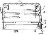
Figure 18 is contained in the scheme drawing that the blind nut of the present invention on the container is analysed and observe vertically;
Figure 19 is the scheme drawing that the blind nut of the 5th embodiment is analysed and observe vertically;
Figure 20 is the scheme drawing that the blind nut of the 6th embodiment is analysed and observe vertically;
Figure 21 is the scheme drawing that the blind nut of the 7th embodiment is analysed and observe vertically;
Figure 22 A, 22B, 22C, 22D have dotted out the front elevational schematic of each embodiment of inner component.
The processing threaded lid of lid 1 for making with plastic material.
At first, this blind nut comprises that one has end cross wall 4 and links to each other with this wall 4 and have the cover piece 3 in tapped skirt section 5.
Secondly this blind nut 1 comprises any type of containment member 7.These members can be integral (see figure 1) with cover piece 3, also can inlay (see figure 4) on this cover piece.
This blind nut 1 comprises that also one manufactures the not broken sleeve 8 of independent member with cover piece 3 at last.
With the coupling member 11 that separates each other along circumference exterior part 9 is linked to each other with the skirt section, these coupling members are between the hanging edge separately 12 and 13 in exterior part 9 and skirt section 5.
When inner component 10 was guided into transverse wall 4, then this inner component just returned in the sleeve 8.
When being screwed blind nut 1 on the container 2, the projection 16 of inner component 10 and container 2 cooperatively interact (seeing Figure 18).
At first vulnerable areas 17 passes to the space 18 between exterior part 9 and the skirt section 5.When turning on when covering, this space 18 is subjected to the restriction of at least one non-brittle joint 19 and can not moves downstream.Above-mentioned non-brittle joint 19 belongs to coupling member 11.The vulnerable areas 17 of exterior part 9 arrives at the vulnerable areas 20a of inner component 10 or otch 20b or its and blocks the 20c of portion then.
When turning on blind nut 1, not broken sleeve 8 still links to each other with cover piece 3.
Used upstream and downstream one speech is for the direction of turning on blind nut.
Used axial, a horizontal speech is for the axis 21 of blind nut.
Zone by " vulnerable areas " expression refers to apply on the plastic material zone that enough power can make later its fracture.This vulnerable areas can partly be made of the attenuation on the plastic material.And the attenuation part can be by the depressed part on the plastic material, and for example groove constitutes.Outside face of parts 9 or inner component 10 (Figure 10 A) or inside face (Figure 10 B) upward or on inside and outside two surfaces (Figure 10 C) are opened such groove outside.
The zone of " otch " expression refers to have on the plastic material zone of rupturing but not having actual space.The typical case of otch is material not to be cut the seam that just has.
The zone of " fracture portion " expression is meant that continuous otch is arranged on the plastic material, and the zone of space 20d is arranged.
Figure 11 A, 11B, 11C have illustrated three kinds of corresponding embodiments of inner component 10.Represent vulnerable areas with 20a on Figure 11 A.Represent otch with 20b on Figure 11 B.Represent to have the fracture portion of space 20d on Figure 11 C with 20C.In the embodiment that is discussed, the vulnerable areas 17 of exterior part 9 is along extending with respect to blind nut axis 21 bevelled general strikes, and its direction is opposite with the direction of screw thread 6, and this can be clear that in Fig. 1 to Fig. 3.The vulnerable areas 20a of inner component 10 or otch 20b extend along the axis 21 bevelled general strikes with respect to blind nut 1.
In first kind of embodiment, this direction is the direction (seeing Figure 17 A) of screw thread 6.The cooresponding situation of this embodiment is: when making blind nut, when inner component 10 arrived on the prolongation of exterior parts 9, vulnerable areas 20a or otch 20b also arrived on the prolongation of vulnerable areas 17 itself.
In second kind of embodiment, the direction of vulnerable areas 20a or otch 20b is identical with the direction of vulnerable areas 17, and is promptly opposite with screw thread 6 directions.This situation occurring is meant: when making blind nut, and vulnerable areas 20a or the otch 20b situation when the general strike of the direction that is symmetrical in vulnerable areas 17 is extended, so-called symmetry trend is with respect to for the Transverse plane at edge 14,15.
The angle of the bevelled general strike between vulnerable areas 17,20a or otch 20b and the axis 21 is 30 °-80 °, preferably is at or about 45 °.
The leaning angle of vulnerable areas 17 is preferably identical with the leaning angle of vulnerable areas 20a or otch 20b.
In the embodiment shown in fig. 12, vulnerable areas 17 is along leading to space 18 with the direction of axis 21 quadratures substantially.Vulnerable areas 17 makes space 18 obviously obtain extending like this, and these characteristics help making vulnerable areas 17 fractures.
In this embodiment, when vulnerable areas 17 with respect to axis 21 during obliquely along straight-line extension, a side at the edge 12 of vulnerable areas 17 ends at introversion section 23.
In the embodiment depicted in fig. 13, the vulnerable areas 17 of exterior part 9 has a section 24 vertical with blind nut axis 21.This section 24 is inserted between two section 24a and 24b that favour axis 21.This layout can be exerted all one's strength and be transmitted along axis 21 directions.
In another unshowned embodiment, vulnerable areas 17 has some sections 24.
Non-brittle joint 19 is close to the end of the vulnerable areas 17 of exterior part 9, and the hanging edge 12 of exterior part is arrived in this end.When turning on blind nut 1, space 18 just enlarges.Can not be when simply turning on non-brittle joint 19 places that blind nut 1 just can rupture when arriving, because vulnerable areas 17 close non-brittle joints 19, so axial force directly affacts vulnerable areas 17.Non-brittle joint 19 helps the breaking force that can make blind nut 1 fracture is sent to vulnerable areas 17.
If non-brittle joint 19 is not fracture when turning on blind nut 1, then for after backing out blind nut, the user just can make its fracture with enough pulling force, and the intensity that can make this non-brittle joint is not very big.
In this embodiment, on the blind nut that in the end takes off, cover piece 3 still links to each other with not broken sleeve.The user can separate not broken sleeve 8 and cover piece 3 like this.So not broken sleeve 8 can not continue to be enclosed within on the material mouth of container 2, and sleeve 8 also can be thrown off with cover piece 3.
The 20c of fracture portion of the inner component 10 that is made of space 20d circumferentially extends around axis 21.The radian of the arc in this space is 20 °-100 °, is preferably 30 °-90 °.The radian of this arc corresponds essentially to the radian of the non-brittle joint 19 of relative set.In the embodiment of Fig. 7, two edges that determined by the 20c of fracture portion of inner component 10 are in several axis plane of blind nut 1.In the embodiment of Fig. 2, these edges branch to hanging edge 22 from attenuation edge 14.
The edge of being determined by the 20c of fracture portion of inner component 10 is at or about 45 ° with respect to the leaning angle of the axis 21 of blind nut 1.
In Fig. 1,4 and 6 embodiment, the axial height of inner component 10 equals the axial height of exterior part 9 at the most.Exterior part 9 just can cover whole inner component 10 like this.Specifically, the axial height of inner component 10 extensions is about half (see figure 4) of the axial height of exterior part 9.
The height that (Figure 14) in another embodiment, inner component 10 extend vertically is greater than the axial height of exterior part 9.Exterior part 9 just partly covers inner component 10 like this, and the part of inner component 10 is vertical with near the skirt section 5 the hanging edge 13.
Shown in these embodiments in, the cross section of axially facing of inner component 10 is generally triangle or trapezoidal, its drift angle is limited by attenuation edge 14, the pairing end, this angle, limited by thick rim 22.Like this, the thickness of inner component 10 14 evenly increases to opposed edges 22 from the edge.
In first kind of embodiment of the present invention, 11 of coupling members are made of some non-brittle joints 19.In the case, exterior part 9 has two vulnerable areas 17 at least, and inner component 10 also has two vulnerable areas 20a at least.Like this, would rather make inner component 10 that vulnerable areas 20a is arranged and do not adopt otch 20b or the 20c of fracture portion, so that constitute a ring that helps fixed outer spare 9 on the inner component 10.
In another embodiment of the invention, coupling member 11 is made of along the fragility bridge 26 that circumference separates each other some non-brittle joints 19 and some, these bridge fractures when backing out blind nut.
The pairing situation of Fig. 1 to 8 embodiment is: coupling member 11 comprises some non-brittle joint 19 and some fragility bridges 26.The pairing situation of Fig. 9 embodiment is: 11 of coupling members are made of some non-brittle joints 19.So there is not fragility bridge 26.
Now particularly with reference to figure 5 and 15.
The cross section of laterally facing of fragility bridge 26 is generally triangular, and near the inside face of skirt section 5 and exterior part 9, cooresponding drift angle is towards the outside at this end at the bottom of the triangle.The configuration of this bridge should make the easy demoulding of blind nut.Make the drift angle of fragility bridge 26 be arranged to fall into more slightly inwards with respect to the outside face of skirt section 5 and exterior part 9.From axial view, fragility bridge 26 is roughly triangle or trapezoidal, and its long limit is against exterior part 9, and drift angle or minor face are near skirt section 5.
In possible embodiment, fragility bridge 26 extends (the fragility bridge of seeing Figure 15 the right) along cardinal principle with respect to the general strike of blind nut axis tilt.This general strike is to tilt along the direction identical with screw thread 6.
Minimum bridge number should be arranged when blind nut of the present invention enbrittles bridge 26, and this minimum bridge number is 4,5 or 6.
Non-brittle joint 19 is first fragility bridge 26 of 45 °-90 ° arc upstream away from radian.
Non-brittle joint 19 can be used for also guaranteeing that sleeve 8 has failure-free and connects when rotating with respect to cover piece 3.
According to another feature, blind nut has a strut member that occurs with the projection form of skirt section 5 and/or exterior part 9 at least, above-mentioned projection from 13,12 1 of hanging edges towards another extension and be arranged in space 18.Its effect is to avoid space 18 to be damaged by pressure when blind nut 1 installs on the container 2.Along circumferential extension, the radian of arc is approximately less than 40 ° on an arc for strut member 27, and two adjacent strut members are separated by at least one fragility bridge 26 or a non-brittle joint 19 each other.Two strut members 27 to each other by four fragility bridges 26 at the most separately.Non-brittle bridge 19 because of strut member 27 away from first fragility bridge 26.The radial wall thickness in the radial wall thickness fundamental sum skirt section 5 of the strut member 27 in close skirt section 5 is identical, and its axial edge rounded (seeing Fig. 5).Strut member 27 has occupied about 1/3rd circumference to half in space 18.Different strut members are shown in Figure 16.First strut member on the left side makes skirt section 5 elongations, and second strut member makes exterior part 9 elongations, and the 3rd strut member both made skirt section 5 elongations, also made exterior part 9 elongations.The 4th is identical with the fwd form with last strut member, and parts of these two parts protrude in another parts, so that can twist-lock.A non-brittle joint 19 is inverted with another non-brittle joint 19 or fragility bridge 26 diametrically.
With reference now to Fig. 1,4,6 and 18,, their expression inner components 10 are with respect to the inclined degree of exterior part 9, and leaning angle is about 10 °-60 °, is about 20 °-40 ° specifically, particularly is at or about 30 °.The application that is provided with of this angle is: can make inner component 10 along the direction of separating 14 rotations around the attenuation edge when turning on blind nut 1.The hanging edge 22 of inner component 10 separates with exterior part 9 or skirt section 5 diametrically.
When being contained in blind nut 1 on the container 2, in case when inner component 10 was return in the sleeve 8, inner component 10 was in before installation on the blind nut 1.Gapped between inner component 10 and the exterior part 9, this gap can make skirt section 5 dwindle with respect to the allowable dimension variation of container 2.Inner component 10 locks tightly more on teat 16 inwardly, and this gap just can be more little, and promptly inner component locks towards the direction of axis 21 rather than towards the outward direction of exterior part 9.
Particularly referring to figs. 1 through Fig. 3, these a few width of cloth accompanying drawings have been represented first kind of embodiment now.
In this embodiment, blind nut 1 has only the 20c of fracture portion of a non-brittle joint 19 and an inner component 10.In another identical embodiment, can replace the fracture 20c of portion with a vulnerable areas 20a or otch 20b.In these illustrated embodiments, there are four fragility bridges 26 to be evenly distributed in substantially on half circumference of blind nut 1, the vulnerable areas 17 of this half circumference and exterior part 9 is relative with the 20c of fracture portion of inner component 10.In addition, three strut members 27 are arranged, wherein two on diameter toward each other, the 3rd is then relative with non-brittle joint 19 on diameter.Like this, when going up, just run into first strut member 27 in succession from vulnerable areas 17 beginning following currents, the first fragility bridge and the second fragility bridge, 26, the second strut members 27, third axle 26, the 3rd 27, the four of (being last) strut member is last bridge 26, runs into non-brittle joint 19 at last.In this embodiment, inner component 10 is opening or closed annular, but should be all-in-one-piece.
Particularly with reference to figure 4, Fig. 5, they represent second embodiment now.
In second embodiment, two non-brittle joints 19 are arranged, they also have the 20c of fracture portion of two inner components 10 radially substantially toward each other, and they are radially also substantially toward each other.As previously mentioned, can replace the fracture 20c of portion with vulnerable areas 20a or otch 20b.
In this embodiment, have six along fragility bridge 26 opposite each other between the footpath, they are positioned at the middle part of exterior part 9.Also have four strut members 27 facing each other, they or separate by fragility bridge 26 or by non-brittle joint 19.Like this when rotating towards the upstream from vulnerable areas 17 beginnings around axis 21, run into first strut member 27 in succession, first, second is the 3rd fragility bridge 26 then, second strut member 27, non-brittle joint 19, vulnerable areas 17, the 3rd strut member 27, four, the 5th the 6th fragility bridge 26 again, the 4th last strut member 27 is second non-brittle joint 19 at last.
Particularly with reference to figure 6,7 and 8, they represent the 3rd embodiment now.
In this embodiment, there are three to be that 120 ° non-brittle joint 19 and three are to each other also with the 20c of fracture portion of the inner component 10 of 120 ° of distributions to each other substantially.In this embodiment, they are positioned at the middle part of inner component 10 each member to each other with the fragility bridge 26 of 120 ° of distributions six, and each member is opened by breaking portion, and relative with non-brittle joint 19 on diameter.Same also have six to each other with the strut member 27 of 120 ° of distributions.From 17 beginnings of first vulnerable areas around axis 21 when clockwise, will run into first strut member 27 in succession, the first and second fragility bridges 26, second strut member 27, non-brittle joint 19, second vulnerable areas 17, the 3rd strut member 27, the third and fourth fragility bridges 26, the four strut members 27, non-brittle joint 19,27, the five of 17, the five strut members of the 3rd (being last) vulnerable areas are the 6th (being last) fragility bridge 26 again, the 6th (being last) strut member 27 arrives at the 3rd non-brittle joint 19 at last.
Particularly with reference to figure 9, the figure shows the 4th embodiment now.The non-brittle joint 19 that four about quadrntnts of being separated by are to each other arranged in this embodiment.Under the situation in embodiment shown in this figure, be that non-brittle joint 19 itself has constituted coupling member 11, blind nut 1 does not have fragility bridge 26.Inner component 10 just has the vulnerable areas 20a of four about quadrntnts of being separated by to each other like this.
In a unshowned embodiment, vulnerable areas 20a or the otch 20b or the 20c of fracture portion of the inner component 10 of the fragility bridge 26 of four apart about quadrntnts and four apart quadrntnts arranged.
According to the present invention, inner component 10 is subjected to the qualification of hanging edge 22, and it is among the plane inclined P with respect to a reference plane R that this hanging edge is in one or several, and reference plane are vertical with blind nut axis 21.
For example plane R is a plane that is limited by the edge 15 of exterior part 9.
In the 5th and the 6th embodiment, hanging edge 22 all is in the identical plane substantially (sees Figure 19 and 20).In the 7th embodiment, hanging edge 22 is in some plane P (sees Figure 21).Under above-mentioned last a kind of situation, inner component 10 can have some some outstanding breach that how much have, and the number of breach is the amount doesn't matter.In the 5th embodiment shown in Figure 19, plane P tilts along the direction of blind nut screw thread 6, and in the 6th embodiment shown in Figure 20, plane P tilts along the opposite sense with blind nut screw thread 6.
Plane P is about 0-10 ° with respect to the leaning angle of plane R, is preferably 3 °-4
According to the present invention (Figure 20 and Figure 21), according to or substantially according to inner component 10 really allocation vulnerable areas 17 is set, at this axial length of determining position inner component 10 for the longest.Should determine that position be exactly " the high point " 30 of hanging edge 22, this height point isolated edge 14 and 15 farthest, and is and nearest from end cross wall 4.
Usually, hanging edge 22 also has " low spot " 31, and it from hanging edge 14 and 15 recently and from wall 4 farthest.
Otherwise, if the preferential height point 30 of selecting is near vulnerable areas 17, then according to inner component 10 allocation or determine that according to it position is provided with vulnerable areas 20a or the otch 20b or the 20c of fracture portion of inner component 10 substantially really, the shortest at this axial length of determining the position inner component, promptly be in maybe this vicinity of low spot 31.
With respect to the reference Transverse plane R1 that is determined by edge 15, plane P has three kinds of positions:
Plane P is along the straight cuts plane R1 (Figure 22 A) tangent with exterior part 9.In the case, then define a 20c of fracture portion by low spot 31 for inner component 10;
Plane P is promptly cut with exterior part 9 (Figure 22 B) at the inner cutting planes R1 of blind nut crossingly.So just can limit the 20c of fracture portion, otch 20b or vulnerable areas 20a by low spot 31;
Be exactly the plane P outside cutting planes R1 (Figure 22 C) of parts 9 outside at last.This has just limited the 20c of fracture portion that passes through " low spot " 31 for inner component 10.
In another embodiment, some has surpassed exterior part in the axial direction inner component 10, and some surpasses exterior part (Figure 22 D).
The method of this blind nut of manufacturing that will describe below is: spray inner component 10 when making exterior part 9 elongation at first.Inner component 10 is rotated, so that make it return to the inside of sleeve 8 around the attenuation edge 14 of self.
So when inner component 10 is return in the sleeve 8, just can be screwed to blind nut 1 on the container 2.
Only certain embodiments of the present invention are described above, obviously those of ordinary skills can make the various modifications that do not exceed the present invention's design according to identical thinking.For example above-mentioned each scheme is made up and all be no more than out design of the present invention.Particularly with the concrete setting of coupling member described in first to the 4th embodiment with relate in hanging edge bevelled the 5th to the 7th embodiment arbitrary scheme and also make up and drop within protection scope of the present invention.
Claims (70)
1, the blind nut of being made by plastic material comprises:
A cover piece (3), this cover piece has
An end cross wall (4) and
The skirt section (5) of negative thread (6) that link to each other with this wall (4) and have;
Install to that described cover piece (3) is gone up or with this cover piece all-in-one-piece containment member (7);
With one be the not broken sleeve (8) of independent member with respect to cover piece (3), this not broken sleeve comprises:
An exterior part (9) that constitutes by sleeve self, this exterior part is arranged on the extension of skirt section (5), it links to each other with the skirt section by coupling member (11), coupling member is the hanging edge (12 of parts (9) and skirt section (5) outside, 13) be provided with along the circle spacing between, be near another edge (15) of exterior part:
Can be around himself attenuation edge (14) with respect to the inner component (10) of exterior part (9) rotation, when described blind nut (1) is screwed on the described container, this inner component (10) be positioned at sleeve (8) inside, cooperate towards end cross wall (4) and with the projection (16) of container (2);
It is characterized in that: the exterior part (9) of described not broken sleeve (8) has a vulnerable areas (17), an opening of vulnerable areas (17) leads to the space (18) between exterior part (9) and skirt section (5), and in described gap (18), described opening the direction with respect to turning on blind nut (1) be that the adjacent position of downstream direction is provided with at least one non-brittle joint (19) as described coupling member (11), vulnerable areas (17) is extended the vulnerable areas (20a) that arrives inner component (10) at the opposite sense of above-mentioned opening always in addition, otch (20b) or fracture portion (20c), thereby after backing out blind nut (1), not broken sleeve (8) still keeps linking to each other with cover piece (3).
2, according to the blind nut of claim 1, it is characterized in that, and described vulnerable areas (17,20a) comprise an attenuation position on corresponding exterior part (9) or inner component (10).
According to the blind nut of claim 2, it is characterized in that 3, this attenuation position is made of the impression on exterior part (9) or the inner component (10), this impression is or/and the fluting on the inside face at the outside face of these two parts.
According to the blind nut of claim 1, it is characterized in that 4, the vulnerable areas (17) on the exterior part (9) is extended obliquely along the axis (21) of the relative blind nut of general strike (1) opposite with screw thread (6) direction.
According to the blind nut of claim 1, it is characterized in that 5, vulnerable areas (20a) on the inner component (10) or otch (20b) extend along axis (21) the bevelled direction with respect to blind nut (1).
According to the blind nut of claim 4, it is characterized in that 6, the angle between the direction of tilt of described vulnerable areas (17) and blind nut (1) axis is 30 °-80 °.
According to the blind nut of claim 5, it is characterized in that 7, the angle between the direction of tilt of described vulnerable areas (20a) or otch (20b) and blind nut (1) axis is 30 °-80 °.
According to the blind nut of claim 6, it is characterized in that 8, the angle between the axis of the direction of tilt of described vulnerable areas (17) and blind nut (1) is 45 °.
According to the blind nut of claim 7, it is characterized in that 9, the angle between the direction of tilt of described vulnerable areas (20a) or otch (20b) and the axis of blind nut (1) is 45 °.
10, according to the blind nut of claim 1, it is characterized in that, the vulnerable areas of exterior part (9) or inner component (10) (17,20a) or otch (20b) extend along rectilinear direction substantially.
11, according to the blind nut of claim 1, it is characterized in that, the vulnerable areas (17) of exterior part (9) with and the perpendicular substantially direction of the axis (21) of blind nut (1) lead in the space (18) between exterior part (9) and skirt section (5), thereby this space (18) is obviously extended.
According to the blind nut of claim 5, it is characterized in that 12, the vulnerable areas (17) of exterior part (9) has the axis (21) of a section (24) perpendicular to blind nut (1) at least, this section be in two sections that favour the blind nut axis (24a, 24b) between.
According to the blind nut of claim 1, it is characterized in that 13, a non-brittle joint (19) is near the end of the vulnerable areas (17) of exterior part (9), the hanging edge (12) that exterior part is led in this end is located.
14, according to the blind nut of claim 1, it is characterized in that, be connected blind nut (1) all the time at blind nut non-brittle joint (19) from the process that described container is backed out.
15, according to the blind nut of claim 1, it is characterized in that, constitute the portion of blocking (20c) of inner component (10) by the space that circumferentially extends (20d) on described vulnerable areas inner component (10).
According to the blind nut of claim 12, it is characterized in that 16, the space (20d) of the portion of blocking (20c) of inner component is 20 °-100 ° opening arc extension along a radian.
17, blind nut according to claim 16 is characterized in that, the radian of described opening arc is 30 °-90 °.
According to the blind nut of claim 15, it is characterized in that 18, the space (20d) of the portion of blocking (20c) of inner component (10) is extended along a corresponding opening arc of the opening with the non-brittle joint (19) of relative set.
19, according to the blind nut of claim 15, it is characterized in that, in two edges that limited by the portion of blocking (20c) of inner component (10) or the several axial planes that are in blind nut (1) substantially, perhaps the thin edges (14) of part (10) is separated towards the hanging edge (22) of this inner component internally.
According to the blind nut of claim 19, it is characterized in that 20, the edge that is limited by the portion of blocking (20c) of inner component (10) and the axis (21) of blind nut (1) are at 45 or approximate 45 ° angle and tilt.
According to the blind nut of claim 1, it is characterized in that 21, exterior part (9) is except its vulnerable areas (17), the thickness on its all peripheries and the axial height is constant, and this thickness is less than or equal to the thickness of skirt section (5).
According to the blind nut of claim 1, it is characterized in that 22, the axial height of inner component (1) equals the axial height of exterior part (9) at the most, exterior part covers inner component (10) fully.
According to the blind nut of claim 22, it is characterized in that 23, the height that inner component (10) extends vertically is about half of axial height of exterior part (9).
According to the blind nut of claim 1, it is characterized in that 24, the height that inner component (10) extends ground vertically surpasses the axial height of exterior part (9), this moment exterior part just part cover inner component (10), and inner component some is vertical with skirt section (5).
According to the blind nut of claim 1, it is characterized in that 25, the cross section of axially facing of inner component (10) is a triangle or trapezoidal.
According to the blind nut of claim 1, it is characterized in that 26, coupling member (11) is made of non-brittle joint (19).
27, according to the blind nut of claim 26, it is characterized in that, exterior part (9) and inner component (10) have at least two vulnerable areas (17,20a).
According to the blind nut of claim 1, it is characterized in that 28, coupling member (11) is made of along the fragility bridge (26) that circumference separates some non-brittle joints (19) and some, when turning on blind nut (1), these bridges are fracture just.
According to the blind nut of claim 28, it is characterized in that 29, the cross section of laterally facing of fragility bridge (26) is generally triangle, the inside face of (5) and exterior part (9) is the leg-of-mutton end against the skirt section, and the drift angle relative end of with is towards the outside.
According to the blind nut of claim 29, it is characterized in that 30, described drift angle slightly falls into inwards with respect to the outside face of skirt section (5) and exterior part (9).
According to the blind nut of claim 28, it is characterized in that 31, the cross section of axially facing of fragility bridge (26) is generally triangle or trapezoidal, against exterior part (9) be long limit, (5) then is drift angle or minor face against the skirt section.
According to the blind nut of claim 28, it is characterized in that 32, fragility bridge (26) extends along the general strike of axis.
According to the blind nut of claim 28, it is characterized in that 33, the general strike of the extension of fragility bridge (26) tilts with respect to the axis (21) of blind nut (11).
According to the blind nut of claim 28, it is characterized in that 34, it comprises 4-6 fragility bridge (26).
35, according to the blind nut of claim 28, it is characterized in that, non-brittle joint (19) is away from the first fragility bridge (26), and this first fragility bridge is near being the position of upstream with respect to the direction that blind nut (1) is backed out from nock, and the radian of described arc is about 45 °-90 °.
According to the blind nut of claim 15, it is characterized in that 36, non-brittle bridge (19) is connected when rotating between sleeve (8) and skirt section (5) with respect to cover piece (3) all the time at sleeve (8).
37, according to the blind nut of claim 15, it is characterized in that, also comprise axial support (27), this strut member is from hanging edge (12,13) beginning is gone up towards the projection of exterior part and/or skirt section extension by skirt section (5) and/or exterior part (9) and is constituted, in the space (18) of above-mentioned projection between skirt section and exterior part.
According to the blind nut of claim 37, it is characterized in that 38, strut member (27) extends on circumference along the arc of radian less than 40 °.
According to the blind nut of claim 37, it is characterized in that 39, two adjacent strut members (27) are separated by fragility bridge (26) or non-brittle joint (19) to each other.
According to the blind nut of claim 37, it is characterized in that 40, two adjacent strut members (27) are separated by four fragility bridges (26) to each other at the most.
According to the blind nut of claim 35, it is characterized in that 41, non-brittle joint (19) is away from the first fragility bridge (26) near the upstream, so-called upstream is for the direction that strut member (27) is turned on blind nut (1).
According to the blind nut of claim 36, it is characterized in that 42, non-brittle joint (19) is away from the first fragility bridge (26) near the upstream, so-called upstream is for the direction that strut member (27) is turned on blind nut (1).
According to the blind nut of claim 37, it is characterized in that 43, non-brittle joint (19) is away from the first fragility bridge (26) near the upstream, so-called upstream is for the direction that strut member (27) is turned on blind nut (1).
According to the blind nut of claim 37, it is characterized in that 44, the radial wall thickness of the strut member of (5) (27) equals the thickness of skirt section (5) substantially against the skirt section, and its edge is circular.
According to the blind nut of claim 37, it is characterized in that 45, strut member (27) occupies about 1/3rd circumference to half in space (18) between skirt section and the exterior part (9).
46, according to the blind nut of claim 28, it is characterized in that, a non-brittle joint (19) is arranged on an end of diameter, and another a non-brittle joint (19) or a fragility bridge (26) are at the other end of this diameter.
According to the blind nut of claim 1, it is characterized in that 47, inner component (10) tilts with respect to exterior part (9), leaning angle is about 10 °-60 °,
According to the blind nut of claim 1, it is characterized in that 48, described leaning angle is 20 °-40 °,
According to the blind nut of claim 1, it is characterized in that 49, described leaning angle is 30 °.
According to the blind nut of claim 1, it is characterized in that 50, the hanging edge (22) of inner component (10) is radially separated with exterior part (9) or skirt section (5).
According to the blind nut of claim 1, it is characterized in that 51, described blind nut comprises a vulnerable areas (20a), otch (20b) or the fracture portion (20c) of a non-brittle joint (19) and inner component (10).
52, according to the blind nut of claim 51, it is characterized in that, four fragility bridges (26) are evenly distributed on half circumference of blind nut (1), and the vulnerable areas (17) of this half circumference and exterior part (9) and vulnerable areas (20a), otch (20b) or the fracture portion (20c) of inner component (10) are corresponding.
According to the blind nut of claim 51, it is characterized in that 53, three strut members (27) are arranged, wherein two mutually corresponding on diameter, the 3rd is then corresponding with non-brittle joint (19) on diameter.
54, according to the blind nut of claim 1, it is characterized in that there are two non-brittle joint respect to one another (19) on the diametric(al) and two equally also vulnerable areas respect to one another (20a), otch (20b) or fracture portion (20c) on diametric(al).
55, according to the blind nut of claim 54, it is characterized in that, have six at the fragility bridge (26) that is in relative to one another on the diametric(al) between each member of inner component (10), these members are separated by two vulnerable areas (20a), otch (20b) or fracture portion (20c) respectively.
56, according to the blind nut of claim 54, it is characterized in that there are four in twos toward each other, the strut member (27) that is separated from each other by fragility bridge (26) or non-brittle joint (19).
57, according to the blind nut of claim 1, it is characterized in that having three to be vulnerable areas (20a), otch (20b) or the fracture portion (20c) of 120 ° non-brittle joint (19) and three inner components (10) that are similarly 120 ° to each other to each other.
According to the blind nut of claim 57, it is characterized in that 58, six middle parts that are in inner component (10) are arranged, and relative on diameter with non-brittle joint (9) be 120 ° fragility bridge (26) to each other.
59, according to the blind nut of claim 57, it is characterized in that having six to be 60 ° of strut members (27) to each other.
According to the blind nut of claim 1, it is characterized in that 60, the non-brittle joint (19) of four quadrntnts that separate each other is arranged.
According to the blind nut of claim 60, it is characterized in that 61, it also is vulnerable areas (20a), otch (20b) or the fracture portion (20c) of quadrntnt of separating each other that the fragility bridge (26) of four quadrntnts that separate each other and four are arranged.
62, according to the blind nut of claim 60, it is characterized in that having only non-brittle joint (19), and the vulnerable areas (20a) of the inner component (10) of four quadrntnts that are spaced apart from each other is arranged as connector (11).
According to the blind nut of one of claim 1 to 62, it is characterized in that 63, inner component (10) is subjected to the qualification of hanging edge (22), this hanging edge is in respect among the reference plane R plane inclined P, and reference plane R is perpendicular to blind nut axis (21).
According to the blind nut of claim 63, it is characterized in that 64, hanging edge (22) all is in unique same plane P.
According to the blind nut of claim 63, it is characterized in that 65, hanging edge (22) is in a plurality of plane P.
According to the blind nut of claim 63, it is characterized in that 66, plane P is about 0 °-10 ° with respect to reference plane R bevelled angle,
67, according to the blind nut of claim 66, it is characterized in that, the angle ranging from 3 °-4
According to the blind nut of claim 64, it is characterized in that 68, vulnerable areas (17) is in the strong point of axial length of inner component (10).
69, according to the blind nut of claim 63, it is characterized in that, vulnerable areas (20a), otch (20b) or the breaking component (20c) of inner component (10) is arranged on the weakness of axial length of inner component (10).
70, according to the blind nut of claim 69, it is characterized in that, the Transverse plane R1 that plane P is limited by edge (15) along the straight line cutting, P plane or tangent with exterior part (9), crossing, or be in outside the exterior part (9).
Applications Claiming Priority (4)
| Application Number | Priority Date | Filing Date | Title |
|---|---|---|---|
| FR9310542A FR2709473B1 (en) | 1993-09-03 | 1993-09-03 | Screw cap and tamper-evident ring, packaging provided with such a stopper, method of manufacturing such a stopper and such packaging. |
| FR93/10542 | 1993-09-03 | ||
| FR93/13180 | 1993-11-05 | ||
| FR9313180A FR2711969B1 (en) | 1993-11-05 | 1993-11-05 | Screw cap with tamper-evident ring. |
Publications (2)
| Publication Number | Publication Date |
|---|---|
| CN1115975A CN1115975A (en) | 1996-01-31 |
| CN1045273C true CN1045273C (en) | 1999-09-29 |
Family
ID=26230577
Family Applications (1)
| Application Number | Title | Priority Date | Filing Date |
|---|---|---|---|
| CN94190833A Expired - Fee Related CN1045273C (en) | 1993-09-03 | 1994-07-29 | Screw cap and tamper-indicating band, package provided with such a cap, method for the manufacture of said cap and package |
Country Status (12)
| Country | Link |
|---|---|
| US (1) | US5779075A (en) |
| EP (1) | EP0641721B1 (en) |
| JP (1) | JP2820798B2 (en) |
| KR (1) | KR960704769A (en) |
| CN (1) | CN1045273C (en) |
| AT (1) | ATE202529T1 (en) |
| BR (1) | BR9407399A (en) |
| CA (1) | CA2170881C (en) |
| DE (1) | DE69427561T2 (en) |
| ES (2) | ES1028707U (en) |
| SG (1) | SG52502A1 (en) |
| WO (1) | WO1995006598A1 (en) |
Families Citing this family (24)
| Publication number | Priority date | Publication date | Assignee | Title |
|---|---|---|---|---|
| JP3256344B2 (en) * | 1993-07-21 | 2002-02-12 | 日本山村硝子株式会社 | Pill fur proof cap |
| CZ215696A3 (en) * | 1995-07-21 | 1997-02-12 | Nord Est Dev | Bottle closure made of plastic material |
| FR2744988B1 (en) * | 1996-02-21 | 1998-04-10 | Nord Est Dev | PLASTIC PLUG HAVING A tamper-evident ring, cap / container assembly, method for making such a cap, and method for making such a cap / container assembly |
| DE19613364C1 (en) * | 1996-04-03 | 1997-11-20 | Weis Kg | Screw cap made of plastic and process for its manufacture |
| AUPO624797A0 (en) * | 1997-04-17 | 1997-05-15 | Amcor Limited | A tamper indicating closure |
| US6981602B2 (en) * | 1997-08-01 | 2006-01-03 | Portola Packaging, Inc. | Tamper evident bottle cap |
| US6059134A (en) * | 1997-10-30 | 2000-05-09 | International Plastics And Equipment Corporation | Snap-on screw-off closure for use in combination with a container |
| IT1300020B1 (en) * | 1998-05-08 | 2000-04-04 | Sacmi | SCREW CAP IN PLASTIC MATERIAL WITH GUARANTEE RING. |
| DE19827242A1 (en) * | 1998-06-18 | 1999-12-30 | Mouldtec Kunststoff Gmbh | Sealing cap, in particular screw cap made of plastic with a guarantee band |
| IT1304486B1 (en) * | 1998-09-09 | 2001-03-19 | Sacmi | SCREW CAP IN PLASTIC MATERIAL WITH GUARANTEE RING. |
| US6381928B1 (en) | 2000-05-26 | 2002-05-07 | Owens-Illinois Closure Inc. | Tamper-indicating closure and container package |
| US6877624B2 (en) * | 2002-01-02 | 2005-04-12 | Erie County Plastics | Method of injection molding closure with continuous internal rigid rib, closure made thereby having a lead-in structure and mold for forming same |
| AU2002951336A0 (en) * | 2002-09-11 | 2002-09-26 | Vere Athol Williamson | Improvements in tamper evident caps |
| ITMO20040203A1 (en) * | 2004-07-30 | 2004-10-30 | Sacmi | MEANS OF CHIUESRA |
| JP2010030639A (en) * | 2008-07-30 | 2010-02-12 | Kazuyuki Okamoto | Cap for container |
| DE102010007010B4 (en) * | 2010-02-05 | 2011-09-01 | Aktiebolaget Skf | Wear bushing |
| JP5007893B1 (en) * | 2011-06-08 | 2012-08-22 | 村山 哲夫 | Pilfer proof cap |
| JP6364234B2 (en) * | 2014-05-19 | 2018-07-25 | 日本クロージャー株式会社 | Screw cap |
| GB2560198B (en) * | 2017-03-03 | 2020-10-07 | Guala Closures Int B V | Tamper evident closure |
| ES2827400T3 (en) * | 2017-11-06 | 2021-05-21 | Aptar Freyung Gmbh | Dispensing closure for a fluid container |
| US11103654B2 (en) | 2018-02-08 | 2021-08-31 | Nordson Corporation | Tamper-evident closure |
| DE102019203855A1 (en) * | 2019-03-21 | 2020-09-24 | Henkel Ag & Co. Kgaa | Packaging system for multi-component product preparations |
| US20220041339A1 (en) | 2020-08-07 | 2022-02-10 | Niagara Bottling, Llc | Single anchor closure |
| US20220177199A1 (en) * | 2020-12-04 | 2022-06-09 | Niagara Bottling, Llc | Multiple asymmetric anchor container closure |
Citations (5)
| Publication number | Priority date | Publication date | Assignee | Title |
|---|---|---|---|---|
| US4352436A (en) * | 1980-11-28 | 1982-10-05 | Consumers Glass Company Limited | Pilferproof cap |
| US4458821A (en) * | 1982-12-09 | 1984-07-10 | Ethyl Molded Products Company | Tamper-indicating closure |
| GB2210031A (en) * | 1987-09-21 | 1989-06-01 | Johnsen Jorgensen Plastics Ltd | Tamper-evident closure |
| WO1991017090A1 (en) * | 1990-04-30 | 1991-11-14 | Anchor Hocking Packaging Corporation | Closure having a spring open tamper evidencing band |
| US5129530A (en) * | 1991-09-09 | 1992-07-14 | Owens-Illinois Closure Inc. | Tamper indicating closure |
Family Cites Families (8)
| Publication number | Priority date | Publication date | Assignee | Title |
|---|---|---|---|---|
| FR2439140A1 (en) * | 1978-10-17 | 1980-05-16 | Bouchons Plastiques | Screwed-on security cap for bottle - has locking ring moulded on and folded back inside cap rim |
| US4206851A (en) * | 1979-02-23 | 1980-06-10 | Ethyl Products Company | Tamperproof closure |
| CH653307A5 (en) * | 1981-12-11 | 1985-12-31 | Walter Wiedmer | SCREW CAP WITH GUARANTEE STRIP FOR CONTAINERS. |
| US4588100A (en) * | 1984-01-18 | 1986-05-13 | Japan Crown Cork Co., Ltd. | Pilfer-proof plastic closure for containers |
| ES2016114B3 (en) * | 1986-07-11 | 1990-10-16 | Interplastic Ag | SAFETY BAND IN A CLOSED TONEL |
| US5056675A (en) * | 1991-01-18 | 1991-10-15 | Sunbeam Plastics Corporation | Tether web ratchet drive tamper indicating band closure |
| US5176270A (en) * | 1991-05-22 | 1993-01-05 | Guala S.P.A. | Tamperproof closure for bottles and the like |
| ES1021753U (en) * | 1992-05-29 | 1993-01-16 | Novembal, S.A. | Break-away safety cap for containers |
-
1994
- 1994-04-14 ES ES09401001U patent/ES1028707U/en not_active Ceased
- 1994-07-29 CA CA002170881A patent/CA2170881C/en not_active Expired - Fee Related
- 1994-07-29 KR KR1019960701076A patent/KR960704769A/en not_active Application Discontinuation
- 1994-07-29 WO PCT/FR1994/000965 patent/WO1995006598A1/en active Application Filing
- 1994-07-29 CN CN94190833A patent/CN1045273C/en not_active Expired - Fee Related
- 1994-07-29 US US08/605,018 patent/US5779075A/en not_active Expired - Fee Related
- 1994-07-29 BR BR9407399A patent/BR9407399A/en not_active IP Right Cessation
- 1994-07-29 JP JP7507977A patent/JP2820798B2/en not_active Expired - Fee Related
- 1994-08-03 ES ES94401785T patent/ES2158882T3/en not_active Expired - Lifetime
- 1994-08-03 EP EP94401785A patent/EP0641721B1/en not_active Expired - Lifetime
- 1994-08-03 SG SG1996005254A patent/SG52502A1/en unknown
- 1994-08-03 AT AT94401785T patent/ATE202529T1/en not_active IP Right Cessation
- 1994-08-03 DE DE69427561T patent/DE69427561T2/en not_active Expired - Fee Related
Patent Citations (5)
| Publication number | Priority date | Publication date | Assignee | Title |
|---|---|---|---|---|
| US4352436A (en) * | 1980-11-28 | 1982-10-05 | Consumers Glass Company Limited | Pilferproof cap |
| US4458821A (en) * | 1982-12-09 | 1984-07-10 | Ethyl Molded Products Company | Tamper-indicating closure |
| GB2210031A (en) * | 1987-09-21 | 1989-06-01 | Johnsen Jorgensen Plastics Ltd | Tamper-evident closure |
| WO1991017090A1 (en) * | 1990-04-30 | 1991-11-14 | Anchor Hocking Packaging Corporation | Closure having a spring open tamper evidencing band |
| US5129530A (en) * | 1991-09-09 | 1992-07-14 | Owens-Illinois Closure Inc. | Tamper indicating closure |
Also Published As
| Publication number | Publication date |
|---|---|
| DE69427561D1 (en) | 2001-08-02 |
| JPH08512016A (en) | 1996-12-17 |
| JP2820798B2 (en) | 1998-11-05 |
| US5779075A (en) | 1998-07-14 |
| EP0641721A1 (en) | 1995-03-08 |
| DE69427561T2 (en) | 2001-10-18 |
| ES1028707U (en) | 1995-03-01 |
| EP0641721B1 (en) | 2001-06-27 |
| CN1115975A (en) | 1996-01-31 |
| KR960704769A (en) | 1996-10-09 |
| BR9407399A (en) | 1996-11-05 |
| ATE202529T1 (en) | 2001-07-15 |
| WO1995006598A1 (en) | 1995-03-09 |
| ES2158882T3 (en) | 2001-09-16 |
| CA2170881A1 (en) | 1995-03-09 |
| CA2170881C (en) | 2000-02-15 |
| SG52502A1 (en) | 1998-09-28 |
Similar Documents
| Publication | Publication Date | Title |
|---|---|---|
| CN1045273C (en) | Screw cap and tamper-indicating band, package provided with such a cap, method for the manufacture of said cap and package | |
| CN1400949A (en) | Synthetic resin filler cap | |
| CN1070446C (en) | Closure device and container thereof | |
| US10723518B2 (en) | Closure | |
| CN1446746A (en) | Holding clamp for bottle plug | |
| RU2578581C2 (en) | Tamper-evident closure and package | |
| CN1239356C (en) | Sealed cover for synthetic resin container | |
| EP1206396B1 (en) | Plastic closure with anti-backoff teeth on its threads | |
| CN1635972A (en) | Spout assembly | |
| CN101044065A (en) | Closure | |
| CN1124403C (en) | Intake port shape of internal combustion engine | |
| RU2004118497A (en) | WIDE NECK COOKING NODE | |
| RU95106777A (en) | COVER, DETECTING OPENING, FOR THREADED EXTERNAL THREAD CONTAINERS, CONTAINERS AND INJECTIVE PRODUCTS | |
| CN1839072A (en) | Cap | |
| CN1524053A (en) | Tamper-evident device | |
| CN1701028A (en) | Tamper evident bottle cap | |
| CN1112783A (en) | Cap | |
| CN101031478A (en) | Capped container | |
| CN1485250A (en) | Cap for container | |
| CN101045479A (en) | Bicycle pedal crank assembly and related elements | |
| CA2517016A1 (en) | Metallic pilfer-proof cap | |
| CN1106987C (en) | Synthetic resin container bearing lable | |
| JP3110194B2 (en) | Container lid | |
| JP2005320055A (en) | Container lid of synthetic resin | |
| CN101076478A (en) | Cap for containers |
Legal Events
| Date | Code | Title | Description |
|---|---|---|---|
| C06 | Publication | ||
| PB01 | Publication | ||
| C10 | Entry into substantive examination | ||
| SE01 | Entry into force of request for substantive examination | ||
| C14 | Grant of patent or utility model | ||
| GR01 | Patent grant | ||
| C19 | Lapse of patent right due to non-payment of the annual fee | ||
| CF01 | Termination of patent right due to non-payment of annual fee |