CN104272032B - Outdoor unit of air conditioner - Google Patents
Outdoor unit of air conditioner Download PDFInfo
- Publication number
- CN104272032B CN104272032B CN201380022388.9A CN201380022388A CN104272032B CN 104272032 B CN104272032 B CN 104272032B CN 201380022388 A CN201380022388 A CN 201380022388A CN 104272032 B CN104272032 B CN 104272032B
- Authority
- CN
- China
- Prior art keywords
- blower
- heat exchanger
- front panel
- outdoor unit
- stage
- Prior art date
- Legal status (The legal status is an assumption and is not a legal conclusion. Google has not performed a legal analysis and makes no representation as to the accuracy of the status listed.)
- Active
Links
Images


Classifications
-
- F—MECHANICAL ENGINEERING; LIGHTING; HEATING; WEAPONS; BLASTING
- F24—HEATING; RANGES; VENTILATING
- F24F—AIR-CONDITIONING; AIR-HUMIDIFICATION; VENTILATION; USE OF AIR CURRENTS FOR SCREENING
- F24F1/00—Room units for air-conditioning, e.g. separate or self-contained units or units receiving primary air from a central station
- F24F1/06—Separate outdoor units, e.g. outdoor unit to be linked to a separate room comprising a compressor and a heat exchanger
- F24F1/60—Arrangement or mounting of the outdoor unit
- F24F1/68—Arrangement of multiple separate outdoor units
-
- F—MECHANICAL ENGINEERING; LIGHTING; HEATING; WEAPONS; BLASTING
- F24—HEATING; RANGES; VENTILATING
- F24F—AIR-CONDITIONING; AIR-HUMIDIFICATION; VENTILATION; USE OF AIR CURRENTS FOR SCREENING
- F24F1/00—Room units for air-conditioning, e.g. separate or self-contained units or units receiving primary air from a central station
- F24F1/06—Separate outdoor units, e.g. outdoor unit to be linked to a separate room comprising a compressor and a heat exchanger
- F24F1/46—Component arrangements in separate outdoor units
- F24F1/48—Component arrangements in separate outdoor units characterised by air airflow, e.g. inlet or outlet airflow
-
- F—MECHANICAL ENGINEERING; LIGHTING; HEATING; WEAPONS; BLASTING
- F24—HEATING; RANGES; VENTILATING
- F24F—AIR-CONDITIONING; AIR-HUMIDIFICATION; VENTILATION; USE OF AIR CURRENTS FOR SCREENING
- F24F1/00—Room units for air-conditioning, e.g. separate or self-contained units or units receiving primary air from a central station
- F24F1/06—Separate outdoor units, e.g. outdoor unit to be linked to a separate room comprising a compressor and a heat exchanger
- F24F1/56—Casing or covers of separate outdoor units, e.g. fan guards
- F24F1/58—Separate protective covers for outdoor units, e.g. solar guards, snow shields or camouflage
-
- F—MECHANICAL ENGINEERING; LIGHTING; HEATING; WEAPONS; BLASTING
- F24—HEATING; RANGES; VENTILATING
- F24F—AIR-CONDITIONING; AIR-HUMIDIFICATION; VENTILATION; USE OF AIR CURRENTS FOR SCREENING
- F24F1/00—Room units for air-conditioning, e.g. separate or self-contained units or units receiving primary air from a central station
- F24F1/06—Separate outdoor units, e.g. outdoor unit to be linked to a separate room comprising a compressor and a heat exchanger
- F24F1/60—Arrangement or mounting of the outdoor unit
Abstract
The invention provides an outdoor unit of an air conditioner, which can be composed of basic small-sized components, and can form an outdoor unit of an air conditioner with large air conditioning capacity by vertically stacking a plurality of small-sized components according to the required air conditioning capacity. The outdoor unit of the air conditioner comprises: the outdoor heat exchanger, the blower assembly and the casing are configured to be capable of being mutually overlapped with other outdoor heat exchanger, blower assembly and casing in a vertical direction.
Description
Technical Field
Embodiments of the present invention relate to an outdoor unit of an air conditioner, which can be variously assembled according to a required air conditioning capacity.
Background
In an air conditioner including indoor units and outdoor units, the number of the indoor units differs depending on the range of a space to be air-conditioned, and accordingly, the outdoor units must be adaptable to different air-conditioning capacities. That is, the outdoor unit has different sizes of its constituent members depending on the required maximum air conditioning capacity (for example, japanese patent application laid-open No. 2008-133986).
The dimensions of the heat exchanger, the blower, and the casing, which are components of the outdoor unit, vary depending on the maximum air conditioning capacity required. Therefore, for each case, separate mold investments are required to form the required dimensions.
In particular, when developing a high-capacity outdoor unit, the size of the metal mold is increased, and a high mold investment is required. Such a large outdoor unit is required to be smaller than a small outdoor unit, and its price tends to increase to recover the investment money.
Disclosure of Invention
In view of the above, there is a demand for an outdoor unit of an air conditioner that can obtain a large air conditioning capacity with an investment in a small-sized metal mold.
An outdoor unit of an air conditioner according to an embodiment includes: the outdoor heat exchanger, the blower assembly and the casing are configured to be capable of being mutually overlapped with other outdoor heat exchanger, blower assembly and casing in a vertical direction.
Drawings
Fig. 1A is a perspective view showing main components of the single-stage outdoor unit according to the present embodiment after being disassembled.
Fig. 1B is a perspective view of the single-unit type outdoor unit in which main components of the single-unit type outdoor unit according to the present embodiment are assembled and then combined with a bottom plate and a top plate.
Fig. 2A is a perspective view showing an assembled single-unit type outdoor unit according to the same embodiment.
Fig. 2B is a rear view showing an assembled single unit type outdoor unit relating to the same embodiment.
Fig. 2C is a left side view showing an assembled single unit type outdoor unit relating to the same embodiment.
Fig. 3 is a perspective view showing a two-stage type outdoor unit assembled with a bottom plate and a top plate after main components according to the same embodiment are assembled.
Fig. 4 is a perspective view showing an assembled two-stage type outdoor unit according to the same embodiment.
Fig. 5 is a perspective view showing a three-stage type outdoor unit in which main components according to the same embodiment are assembled and combined with a bottom plate and a top plate.
Fig. 6 is a perspective view showing an assembled three-stage type outdoor unit according to the same embodiment.
Fig. 7A is a perspective view showing a blower bracket used in the three-stage outdoor unit according to the present embodiment.
Fig. 7B is a side view showing a blower bracket used in the three-stage outdoor unit according to the present embodiment.
Fig. 8A is a perspective view showing a process in a process of manufacturing a three-stage outdoor unit according to the same embodiment.
Fig. 8B is a longitudinal sectional view showing a process in manufacturing the three-stage type outdoor unit according to the same embodiment.
Fig. 9 is a perspective view further showing a process in the process of manufacturing the three-stage type outdoor unit according to the same embodiment.
Fig. 10 is a perspective view for further explaining a process in the manufacturing process of the three-stage type outdoor unit according to the same embodiment.
Fig. 11A is a perspective view showing a side rear plate used in a three-stage type outdoor unit according to the same embodiment.
Fig. 11B is a view showing a connection structure of upper and lower side back plates used in a three-stage outdoor unit according to the same embodiment.
Fig. 12 is a schematic diagram of various outdoor units according to the same embodiment.
Detailed Description
Hereinafter, the present embodiment will be described with reference to the drawings. The outdoor unit of the air conditioner described in detail below is selected from a "single-stage type outdoor unit", a "two-stage type outdoor unit", and a "three-stage type outdoor unit" according to a required maximum air conditioning capacity. In particular, the overall height dimension of the "three-stage type outdoor unit" is about 1800mm, which is basically the maximum upper limit of the size that can be accommodated by the freight elevator.
Although the "four-stage type outdoor unit" and the outdoor units larger than the "four-stage type outdoor unit" can be theoretically manufactured, there is a possibility that transportation and arrangement are hindered, and the outdoor unit is not realistic as an outdoor unit installed in each floor of an apartment house or the like, for example, and therefore, description thereof is omitted.
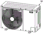
First, a description will be given of a single-stage outdoor unit 1M that is suitable for an air conditioner of small capacity requiring a maximum air conditioning capacity of about 2 horsepower (2 hp).
Fig. 1A is a perspective view showing a single-stage outdoor unit 1M with its main components exploded. Fig. 1B is a perspective view of the single-stage outdoor unit 1M in which the main component assembly S, the bottom plate 10, and the top plate 11 are disassembled. Fig. 2A is an external perspective view showing the assembled single-stage outdoor unit 1M. Fig. 2B is a rear view of the single-unit type outdoor unit 1M. Fig. 2C is a left side view of the single-unit type outdoor unit 1M.
The small-capacity single-stage outdoor unit 1M is constituted by a heat exchanger 2, a blower unit 3, and a casing 4.
As shown in fig. 1A, the heat exchanger 2 is a fin-tube type heat exchanger formed in a substantially L-shape in plan view. Along one of the side portions, the U-bend of the heat exchange tube is protruded, and along the other side portion, the U-bend, the distribution tube and the collecting tube 5 are provided. The manifold 5 is connected to a cooling cycle component such as a compressor or an expansion valve via a pipe not shown.
The blower unit 3 includes a blower 8 and a blower holder 9 for supporting the blower 8, and the blower 8 includes a fan motor 6 and a fan 7 attached to a rotary shaft of the fan motor 6. The blower support 9 is a vertically long frame body, and supports the fan motor 6 at a substantially central portion. A bottom plate mounting portion 9a bent into a substantially L shape is provided at the lower end of the blower bracket 9, and a front plate mounting portion 9b bent forward and a heat exchanger supporting portion 9c bent toward the back side are mounted at the upper end of the blower bracket 9.
The casing 4 is composed of a bottom plate 10 forming a bottom, a top plate 11 forming a ceiling, a side surface 12 located between the bottom plate 10 and the top plate 11, and a partition plate 13 partitioning the inside of the casing 4 into a heat exchange chamber 30 and a machine chamber 31. The outdoor heat exchanger 2 and the blower unit 3 are accommodated in the heat exchange chamber 30, and the compressor and the pipes are accommodated in the machine chamber 31.
The bottom plate 10 has a rectangular shape in plan view, and is provided with a folded-back portion 10a along its peripheral edge. Two support legs 10b are attached to the lower surface of the base plate 10 in parallel with the width direction of the housing 4, and attachment portions 10c protrude from four corners of the base plate 10. The mounting portion 10c is set in advance at a mounting position, and a fixing member such as an anchor is inserted, and the single-stage outdoor unit 1M can be fixed at the mounting position by a nut or the like.
Further, the bottom plate 10 is integrally provided with a projection Xc for positioning the outdoor heat exchanger 2, a projection Xc for positioning the blower holder 9, a projection Xc for positioning the partition plate 13, a projection Xc for positioning the compressor communicating with the outdoor heat exchanger 2 via a pipe, and the like. The protrusion heights of these protrusions Xc are all the same.
The top plate 11 is formed in a rectangular shape having the same plane as the bottom plate 10, and a protrusion portion for maintaining rigidity is provided on the plane portion. A folded part 11a is provided along the periphery of the protrusion part, and a hooking recess Xf for inserting and attaching a fixing tool is provided on the side surface part.
The front panel 15, the side front panel 16, and the side rear panel 17 are provided with connecting portions Xd for connecting to each other at their respective opposite side edge portions, and the connecting portions Xe for fitting the top panel 11 are provided at the upper end portions of the front panel 15, the side front panel 16, and the side rear panel 17. A hooking recess Xf for inserting and fixing the attachment in a state of being fitted into the bottom plate 10 is provided at the lower end of the side surface part 12.
The front panel 15 serves as the casing 4, and in an assembled state, one bell mouth 15a is integrally provided at a position facing the front surface of the blower fan 7. In order to cover the bell mouth 15a, a detachable fan cover 20 having a straight upper edge and right and left side edges and a circular lower edge is attached.
In practice, when fixing the single-stage outdoor unit 1M at the mounting position, a fixing member such as an anchor is inserted into the mounting portion 10c of the support leg 10b, and when fastening a nut or the like, the fan cover 20 is formed in a semicircular shape, so that the fan cover 20 does not become an obstacle during the mounting work.
The fin cover 18 is formed by combining a plurality of vertically and horizontally wire-shaped objects, and the fin cover 18 is located at a position facing the outdoor heat exchanger 2 in a state where the fin cover is assembled to the casing 4. The fin cover 18 is attached to the front panel 15 at one side portion thereof and to the side rear panel 17 at the other side portion thereof via a stay 19.
The partition plate 13 is provided with a front folded portion 13a along the front surface, a rear folded portion 13b along the rear surface, a lower end connecting portion 13c along the lower end portion, and an upper end connecting portion 13e along the upper end portion.
The outdoor heat exchanger 2, the portion from the bottom plate mounting portion 9a of the blower fan bracket 9 to the upper heat exchanger branch portion 9c, and the partition plate 13 configured as described above are set at the same height. Therefore, when the outdoor heat exchanger 2, the blower fan holder 9, and the partition plate 13 are placed on the protrusion Xc of the bottom plate 10 constituting the casing 4, the height positions of the upper ends of these components are the same.
In the assembled state in which side surface part 12 is fitted into folded part 10a of bottom plate 10, the bottom part of bottom plate 10 and the lower end edge of side surface part 12 above it are all aligned, and side surface part 12 is composed of front panel 15, side surface front panel 16, and side surface rear panel 17.
The front panel 15, the side front panel 16, and the side rear panel 17 have connection portions Xe at their upper ends, and the height of the connection portions Xe is equal to the height of the protrusions Xc provided on the base panel 10. The lower end of the connection part Xe, the outdoor heat exchanger 2 on the bottom plate 10, the heat exchanger support part 9c of the blower mount 9, and the upper end of the partition plate 13 are all at the same height.
Fig. 1B shows a state where the bottom plate 10 and the top plate 11 are assembled to the main component assembly S, and the assembly is actually performed as described below.
First, a compressor is disposed on the base plate 10, and is fixed by a fixing member such as a screw. The outdoor heat exchanger 2 and the blower support 9 of the blower unit 3 are sequentially attached to the protrusion Xc formed in the bottom plate 10 by the attachment. Here, the heat exchanger support portion 9c provided on the blower bracket 9 is hooked to the upper end portion of the outdoor heat exchanger 2.
Next, the distribution pipe and the collecting pipe 5 connected to the compressor and the outdoor heat exchanger 2, and the four-way valve not shown, and the like are connected by welding via refrigerant pipes. Then, the partition plate 13 is attached to the projection Xc of the bottom plate 10 by the attachment, and the rear folded portion 13b is attached to an end plate, not shown, of the outdoor heat exchanger 2 by the attachment.
Further, a fan motor 6 is mounted on the blower holder 9, and a fan 7 is mounted on a rotary shaft of the fan motor 6. Then, an electric component box (not shown) housing a control board for driving the compressor, the fan motor 6, the four-way valve, and the like is disposed above the machine room 31, and signal lines of various sensors and wiring such as power lines of the compressor and the fan motor 6 are connected to the electric component box.
Next, the lower end of front panel 15 constituting side surface part 12 is attached to folded part 10a of floor panel 10 by a mounting tool. The front panel mounting portion 9b of the blower support 9 is mounted and hooked on an upper end portion of the front panel 15 by a mounting member.
Since only the front mounting portion 9b is recessed with respect to the other portions, it does not become an obstacle to mounting the top plate 11 later. The front folded-back portion 13c of the partition plate 13 is attached to the front panel 15 by a mounting tool. A fan cover 20 is mounted on the front panel 15.
Next, the lower end of the side rear panel 17 is attached to the folded portion 10a of the bottom panel 10, and the top panel 11 is fitted to the connection portion Xe at the upper ends of the front panel 15 and the side rear panel 17. A support 19 is attached to a corner of the left and rear surfaces of the case 4 so as to pass through the bottom plate 10 and the top plate 11. The fin cover 18 is attached to the front panel 15 and the side rear panel 17 via the support posts 19.
Finally, a side front plate 16 is disposed between the front panel 15 and the side rear plate 17, and the opposing side portions are combined, and a connecting portion Xe at the upper end of the side front plate 16 is fitted into the top plate 11, and the lower end portion of the side front plate 16 is attached to the folded portion 10a of the bottom plate 10 by a fitting.
Thus, the single-stage outdoor unit 1M is completed.
In the previously described sizing, the positions of the lower end edges of the front panel 15, the side front panel 16, and the side rear panel 17 constituting the case side surface part 12 are all aligned, and the height positions of the lower end part of the upper end joining part e, the outdoor heat exchanger 2, the heat exchanger support part 9c of the blower fan holder 9, and the upper end edge of the partition plate 13 are all aligned, in the state of the main component assembly S.
The dimensions of the lower end of the outdoor heat exchanger 2, the bottom plate attachment portion 9a of the blower fan holder 9, and the projection Xc of the bottom plate 10 that supports the lower end of the partition plate 13 are set so as to match the height dimensions of the joint Xe of the front plate 15, the side front plate 16, and the side rear plate 17 that constitute the case side surface portion 12.
Therefore, as shown in fig. 2A, 2B, and 2C, the single-stage outdoor unit 1M is assembled. In a state where the top plate 11 is mounted to cover the components including the outdoor heat exchanger 2, the blower fan holder 9, the side surface portion 12, the partition plate 13, and the like, there is no room for a gap between each component and the top plate 11, and the assembly can be performed reliably.
In addition, the maximum air conditioning capacity required for the outdoor unit of the air conditioner may be, for example, 1.5 to 2 times that of the single-stage type outdoor unit 1M, and may be 3 horsepower (3 hp). In order to meet such a demand, a compressor having a larger capacity than that of the single-stage type outdoor unit 1M may be used, and a "deformed single-stage type outdoor unit" in which the sizes of the constituent members are changed (only the size in the vertical direction is enlarged) is employed.
In this modified single-stage outdoor unit, all the constituent elements of the outdoor heat exchanger 2, the blower holder 9, the side surface 12, the partition plate 13, and the like, which are the same as those of the single-stage outdoor unit 1M described above, are set at the same height, which is a condition that is completely unchanged.
Therefore, in the case of such a modified single-stage type outdoor unit, the size of the metal mold for manufacturing the constituent members can be obtained by increasing a certain size with respect to the metal mold of the single-stage type outdoor unit 1M, and the modified single-stage type outdoor unit can be developed with relatively little investment.
Next, an outdoor unit of an air conditioner in which the required maximum air conditioning capacity is 2.5 to 3 times that of the conventional single-stage outdoor unit 1M and 5 horsepower (5hp) to 6 horsepower (6hp), that is, a two-stage outdoor unit 2M will be described.
Fig. 3 is a perspective view showing the two-stage outdoor unit 2M. Fig. 4 is an external perspective view of the assembled two-stage outdoor unit 2M.
The two-stage outdoor unit 2M is configured to: the two heat exchangers 2, the two blower assemblies 3 including the blowers, and the two casings 4 are stacked on each other in the vertical direction. Although two side surface portions 12 of the housing 4 are necessary, one bottom plate 10 and one top plate 11 may be used.
That is, as shown in fig. 3, on the bottom plate 10, two main component assembly bodies S, which have been previously described in fig. 1B, are stacked in the vertical direction, and a top plate 11 is crowned at the upper end thereof.
In practice, a compressor is disposed on the base plate 10, and the outdoor heat exchanger 2 and the blower fan holder 9 are mounted in a single set. Then, another set of the outdoor heat exchanger 2 and the blower fan support 9 is stacked on the respective components.
Necessary piping is inserted between the compressor and the two sets of outdoor heat exchangers 2, and the pipes are welded to be connected. Then, the partition plate 13 is attached to the base plate 10, and one partition plate 13 is further attached to the partition plate 13. Fan motors 6 are mounted on the respective blower brackets 9, and fans 7 are mounted on the respective fan motors 6.
Then, an electrical component box is disposed in the machine room 31 on the upper stage side, and signal lines of various sensors and wiring such as a power supply line of the compressor and the fan motor 6 are connected to the electrical component box. A lower front panel 15 is attached, and an upper front panel 15 is attached to the lower front panel 15. Then, the fan covers 20 are attached to the upper and lower front panels 15, respectively.
Next, the side rear plate 17 of the lower stage is attached, and the side rear plate 17 of the upper stage is attached to the side rear plate 17. In this state, the top panel 11 is fitted into a connection Xe between the upper ends of the upper front panel 15 and the upper side rear panel 17.
A support 19 is attached to a corner of the left and rear surfaces of the case 4 so as to pass through the bottom plate 10 and the top plate 11. The support column 19 used herein has a length dimension 2 times as large as that of the previously described support column 19 used in the single unit type outdoor unit 1M. By this stay 19, two sets of fin covers 18 in the vertical direction (both not shown in the drawing) are mounted to the front panel 15 and the side rear panel 17.
Next, the upper side front panel 16 is disposed between the upper front panel 15 and the side rear panel 17, and the connection part Xe at the upper end of the upper side front panel 16 is fitted into the top panel 11 and attached by the attachment. Finally, the lower-stage side front panel 16 is disposed between the lower-stage front panel 15 and the lower-stage side rear panel 17, the connection portion Xe of the upper end of the lower-stage side front panel 16 is fitted to the lower end of the upper-stage side front panel 16, and the lower end of the lower-stage side front panel 16 is attached to the folded portion 10a of the floor panel 10 by the attachment.
Thus, the secondary type outdoor unit 2M is completed.
In the case where the required maximum air conditioning capacity is, for example, 4 to 5 times that of the single-stage outdoor unit 1M and 8 to 10 horsepower (8hp) to 10hp, the present invention may be applied to a "hybrid two-stage outdoor unit" in which the above-described modified outdoor unit and the single-stage outdoor unit 1M are combined, or may be applied to a "modified two-stage outdoor unit" in which two modified single-stage outdoor units are combined.
In any of the above cases, since the outdoor heat exchanger 2, the blower unit 3, and the casing 4 can be assembled in the vertical direction, a large-sized (two-stage) outdoor unit can be constructed using small-sized equipment and parts made by small-sized metal molds.
Since the interfaces of the constituent members stacked in the vertical direction are all set at the same height position, there is no room for a gap, and other members for adjusting the size are not required, and cost reduction can be achieved without trouble.
Since all of the outdoor heat exchanger 2, the fan unit 3, and the casing 4 have the same shape in the vertical direction, the two-stage outdoor unit 2M, which is an outdoor unit of a two-stage size, can be manufactured by only using a die investment for manufacturing the first-stage constituent members. Alternatively, a hybrid two-stage type outdoor unit or a modified two-stage type outdoor unit can be manufactured by adding a mold investment for manufacturing the first-stage constituent members of the modified single-stage type outdoor unit.
Next, an outdoor unit of an air conditioner, i.e., a three-stage type outdoor unit 3M, in which the required maximum air conditioning capacity is 5 to 6 times that of the single-stage type outdoor unit 1M and 10 to 12 horsepower (10 to 12hp) will be described.
Fig. 5 is a perspective view showing a three-stage type outdoor unit. Fig. 6 is an external perspective view of the assembled three-stage outdoor unit. Fig. 7A is a perspective view showing a state in which three blower brackets 9 are assembled, and fig. 7B is a side view of fig. 7A.
The three-stage outdoor unit 3M is configured to: three heat exchangers 2, three blower assemblies 3 including blowers, and three cases 4 are stacked on each other in the vertical direction. However, although three side surface portions 12 constituting the housing 4 are necessary, one bottom plate 10 and one top plate 11 may be used.
As shown in fig. 5, on the bottom plate 10, three main component assembly bodies S, which have been previously described in fig. 1B, are stacked in the vertical direction, and a top plate 11 is crowned at the upper end. Accordingly, as shown in fig. 6, the three-stage type outdoor unit 3M is completed.
Actually, the respective constituent members are assembled as follows.
First, the compressor 21 and the gas-liquid separator 22 are disposed on the base plate 10 and fixed by the fixture. Then, the lowest stage blower support 9 is placed on the projection Xc provided at a predetermined position on the bottom plate 10, and is fixed by a fixing member such as a screw.
Further, one outdoor heat exchanger 2 is prepared, and the outdoor heat exchanger 2 is placed on a predetermined portion of the base plate 10, the predetermined portion being a protrusion Xc along one side portion and the rear surface portion of the base plate 10. Along the upper end portion on the back side of the outdoor heat exchanger 2, the heat exchanger support portion 9c is hooked, and the heat exchanger support portion 9c is provided to protrude from the blower support 9 on the lowest stage.
Then, a blower support 9 is prepared, and the blower support 9 as the middle-stage blower support 9 is superposed on the lowest-stage blower support 9. More specifically, an upper mounting portion 9d is provided between a front panel mounting portion 9b formed at an upper end portion of the lowest stage blower support 9 and the heat exchanger support portion 9c, and a bottom plate mounting portion 9a of the middle stage blower support 9 is mounted on the upper mounting portion 9d and fixed thereto by means of, for example, screws.
The upper mounting portion 9d has the same protruding shape as the protruding portion Xc of the bottom plate 10, and can reliably position the bottom plate mounting portion 9a of the middle-stage blower support 9.
Further, another outdoor heat exchanger 2 is stacked as an intermediate-stage outdoor heat exchanger 2B on the lowest-stage outdoor heat exchanger 2A, which lowest-stage outdoor heat exchanger 2A has been placed on the bottom plate 10. The lower end of the intermediate-stage outdoor heat exchanger 2B and the lowest-stage outdoor heat exchanger 2A sandwich the heat exchanger support portion 9c of the lowest-stage blower support 9A, and the upper end of the intermediate-stage outdoor heat exchanger 2B is hooked to the heat exchanger support portion 9c of the intermediate-stage blower support 9B.
Then, another blower support 9 is stacked on the blower support 9 of the middle stage as the blower support 9 of the uppermost stage. Specifically, a bottom plate mounting portion 9a for positioning the uppermost fan bracket 9 is mounted on an upper mounting portion 9d formed at an upper portion of the middle fan bracket 9 and is fixed thereto by means of screws or the like, for example.
Then, one outdoor heat exchanger 2 is prepared again, which is stacked as the uppermost-stage outdoor heat exchanger 2C on the middle-stage outdoor heat exchanger 2B. The lower end of the uppermost outdoor heat exchanger 2C and the intermediate outdoor heat exchanger 2B sandwich the heat exchanger support portion 9C of the intermediate blower support 9B, and the upper end of the uppermost outdoor heat exchanger 2C is hooked to the heat exchanger support portion 9C of the uppermost blower support 9C.
By placing the three heat exchangers 2 as described above, the side surface manifolds 5 of the respective heat exchangers 2 are in contact with each other, and therefore, the manifolds 5 are integrally connected to each other by welding or the like. This state is shown in fig. 8A.
In addition, the longitudinal sectional view of fig. 8A is shown in fig. 8B. As shown in fig. 8B, the lower end of the outdoor heat exchanger 2A on the lowest stage and the lower surface of the bottom plate mounting portion 9a on the blower support 9 on the lowest stage are placed on the protrusion Xc of the bottom plate 10 to have the same height (L1 in the drawing).
The heights of the upper end portion of the lowest-stage outdoor heat exchanger 2A, the heat exchanger support portion 9c of the lowest-stage blower support 9a, and the upper end portion of the upper mounting portion 9d are also the same (L2 in the drawing). Similarly, the heights of the upper end of the intermediate-stage outdoor heat exchanger 2B, the heat exchanger support portion 9c of the intermediate-stage heat exchanger bracket 9, and the upper end of the upper mounting portion 9d are also the same (L3 in the drawing).
Further, the heights of the upper end portion of the outdoor heat exchanger 2C on the uppermost stage, the heat exchange support portion 9C of the heat exchanger rack 9 on the uppermost stage, and the upper end portion of the upper mounting portion 9d are also the same (L4 in the drawing). Furthermore, the dimensions between L1 and L2, between L2 and L3, and between L3 and L4 are all the same.
Fig. 9 is a perspective view of the three-stage outdoor unit 3M in a further assembling process. In the state shown in fig. 8A, the compressor 21, the gas-liquid separator 22, the oil separator 23, the four-way valve 24, the distribution pipe, and the collecting pipe 5 are welded and connected by the pipe K.
At this time, the pipe K and the cooling cycle components such as the compressor 21 are accommodated in the space corresponding to the two stages of the lowest stage and the middle stage of the machine chamber 31. In the space corresponding to the uppermost machine room 31, only the distribution pipe and the collecting pipe 5 connected to the uppermost heat exchanger 2C are provided, and the cooling cycle components such as the pipe K and the compressor 21 are not provided.
Next, the partition plate 13 at the lowermost stage is attached to a predetermined portion of the bottom plate 10. An electrical component box H is attached to an upper portion of the partition plate 13.
Fig. 10 is a perspective view showing a state in which the electric component box H in fig. 9 is mounted. In the electric component box H, a drive control unit for electrically controlling the blower 8, the compressor 21, and the like, and a signal control unit for controlling various signals are housed.
The electric component box H is integrally formed with the intermediate-stage partition plate 13 and partitioned into the heat exchange chamber 30 and the machine chamber 31, but a part of the electric component box H protrudes from the heat exchange chamber 30. The protruding portion is a heat sink Xg for cooling a high-power component that is liable to generate heat, such as a power module of an inverter that drives the compressor 21 and the blower 8.
A partition plate 13 at the uppermost stage is attached to the upper portion of the electrical component box H. Then, the fan motors 6 are mounted on the three blower brackets 9, respectively, and the fans 7 are mounted on the fan motors 6. In this way, the blower assembly 3 is completed. In this state, signal lines of various sensors and power lines of the compressor 21 and the blower 8 are connected to the electric component box H.
Next, the lowermost front panel 15 is attached, the intermediate front panel 15 is attached to the front panel 15, and the uppermost front panel 15 is attached to the intermediate front panel 15. A fan cover 20 is attached to each of these front plates 15.
Next, the side rear plate 17 of the lowest stage is attached, the side rear plate 17 of the middle stage is attached to the side rear plate 17, and the side rear plate 17 of the highest stage is attached to the side rear plate 17 of the middle stage. Then, the upper end connection portion Xe of the uppermost front panel 15 and the uppermost side rear panel 17 is fitted into the top panel 11.
Next, a support 19 is attached to the corner of the left and rear surfaces of the case 4 so as to pass through the bottom plate 10 and the top plate 11. The support column 19 used here has a length dimension three times as large as that of the support column 19 used in the conventional single-stage type outdoor unit 1M. The three sets of fin covers 18 are attached to the front panel 15 and the side rear panel 17 in the vertical direction by the support posts 19.
Further, the side front panel 16 on the uppermost stage is disposed between the front panel 15 on the uppermost stage and the side rear panel 17, and the connection part Xe at the upper end of the side front panel 16 is fitted into the top panel 11 and attached by a mounting tool. The intermediate side front panel 16 is disposed below the uppermost side front panel 16, and the connection part Xe at the upper end of the intermediate side front panel 16 is fitted to the lower end of the uppermost side front panel 16 and attached by a mounting tool.
Finally, the lowermost side front panel 16 is disposed below the intermediate side front panel 16, and the connection part Xe at the upper end of the lowermost side front panel 16 is fitted to the lower end of the intermediate side front panel 16 and attached by a mounting tool. Then, the lower portion of the side front panel 16 on the lowermost stage is attached to the folded back portion 10a of the floor panel 10 by the attachment.
In this way, the three-stage type outdoor unit 3M described above with reference to fig. 6 is completed.
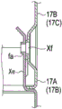
Hereinafter, a vertical connection structure of the side surface part 12 constituting the housing 4 will be described by taking the side surface back plate 17 as an example.
Fig. 11A is a diagram showing a state in which three side rear plates 17 forming the right and rear surfaces of the housing 4 are integrated. Fig. 11B is a connection structure diagram of the upper and lower side back plates 17. In the case of the side rear panel 17, the lower end portion of the middle stage side rear panel 17B is fitted into a connection portion Xe formed at the upper end portion of the lowermost stage side rear panel 17A.
At this time, as shown in fig. 11B, the hole fa provided in the connection portion Xe of the lowermost side rear panel 17A faces the hooking recess Xf provided in the lower end portion of the intermediate side rear panel 17B. Therefore, by inserting and fixing the mounting pieces, not shown, into the hooking recess Xf and the holes fa, the lowermost side rear plate 17A and the intermediate side rear plate 17B can be connected and fixed to each other.
Similarly, the lower end of the uppermost side rear plate 17C is fitted into the connection portion Xe formed at the upper end of the intermediate side rear plate 17B. At this time, the hole fa provided in the connection portion Xe of the middle-stage side rear plate 17B faces the hooking recess Xf provided in the lower end portion of the uppermost-stage side rear plate 17C, and therefore can be connected and fixed by the mounting. By this, the three side rear plates 17 are connected.
Although the vertical connection structure of the side surface part 12 of the housing 4 has been described above by taking the side surface rear plate 17 as an example, the front plate 15 and the side surface front plate 16 are connected to the side surface rear plate 17 in the same structure. However, the side front panel 16 is different from the front side panel 15 and the side rear panel 17 in that the side front panel is connected in the order of the uppermost stage, the middle stage, and the lowermost stage.
Since the three-stage outdoor unit 3M can be constructed by assembling the outdoor heat exchanger 2, the blower unit 3, and the casing 4 in the vertical direction, a large-sized (three-stage) outdoor unit can be constructed by small-sized equipment and parts made by small-sized molds.
Since the interfaces of the components stacked in the vertical direction are all set at the same height position, there is no room for a gap, and other components for adjusting the size are not required, and cost reduction can be achieved without trouble.
Since all of the outdoor heat exchanger 2, the fan unit 3, and the casing 4 have the same shape in the vertical direction, the three-stage outdoor unit 3M, which is an outdoor unit having three stages of sizes, can be manufactured only by investing in molds for manufacturing the first-stage components.
In the three-stage outdoor unit 3M described above, the electric component box H is provided at the same position as the second-stage (intermediate-stage) outdoor heat exchanger 2, and the pipe K is provided through the first-stage (lowermost-stage) outdoor heat exchanger 2 and the second-stage outdoor heat exchanger 2.
Here, the two-stage outdoor unit 2M described above with reference to fig. 3 and 4 can be obtained by removing the third-stage (uppermost stage) outdoor heat exchanger 2, the blower unit 3 including the blower 8, and the side surface portion 12 of the casing 4.
Further, in the process of newly developing models, when more piping space is required, the piping space can be easily secured by moving the electrical component box to the third stage. In this way, the convenience of design is improved by modularization.
Fig. 12 shows a structure of various outdoor units.
The heat exchanger is roughly classified into three types, that is, "1 FAN case" in which one outdoor heat exchanger, blower, and case is provided, two "2 FAN cases" in which two outdoor heat exchangers, blowers, and cases are provided, and "3 FAN case" in which three outdoor heat exchangers, blowers, and cases are provided.
In the 1FAN case, initial investment is made for a "single-stage type outdoor unit" having a maximum air conditioning capacity of 2ph as a standard. The casing height dimension H of the single-stage type outdoor unit is 600 mm.
Meanwhile, after the single-stage outdoor unit is used as a basis for improvement, the second round of investment is carried out on the 'deformed single-stage outdoor unit' with the maximum air conditioning capacity of 3ph or 4 hp. The casing height dimension H of the deformed single-stage type outdoor unit is 890 mm.
In the 2FAN case, "the second-stage outdoor unit" in which two single-stage outdoor units are stacked, "the hybrid second-stage outdoor unit" in which one single-stage outdoor unit and one deformed single-stage outdoor unit are stacked, "the deformed second-stage outdoor unit" in which two deformed single-stage outdoor units are stacked "are invested.
The height dimension H of the secondary type outdoor unit is 600mm × 2, and the maximum air conditioning capacity is 5hp or 6 hp. The height dimension H of the hybrid type outdoor unit is 600mm +890mm, and the maximum air conditioning capacity is 8 hp. The height dimension H of the outdoor unit of the deformed secondary type is 890mm × 2, and the maximum air conditioning capacity is 10 hp.
In the 3FAN case, investment is expanded for a "three-stage type outdoor unit" in which three single-stage type outdoor units are stacked. The height dimension H of the three-stage type outdoor unit is 600mm × 3, and the maximum air conditioning capacity is 10hp or 12 hp.
With such a single-stage outdoor unit 1M as a basis, a total array configuration of six outdoor units can be obtained, and the degree of freedom in design can be increased.
Since the 2FAN casing and the 3FAN casing are stacked in the vertical direction, the outdoor unit of a large-sized air conditioner can be manufactured according to the required maximum heat exchange capacity by small-sized equipment and parts manufactured by small-sized metal molds.
Even when the components having different vertical height dimensions are stacked, the vertical ports of each outdoor unit are set to have the same height as each other in the components. Therefore, the overlapping dividing lines are aligned, and it is not necessary to require different sizes of constituent members in one group.
Since the outdoor heat exchanger, the blower assembly, and the casing are all set to the same shape as each other in the vertical direction, the outdoor unit can be manufactured in a multi-stage stack using only investment in molds for manufacturing one stage.
Since the outdoor heat exchanger 2, the blower assembly 3, and the casing 4 have the connection portions (the hooking recess portions Xf and the hole portions fa) that can connect the other outdoor heat exchanger 2, the blower assembly 3, and the casing 4 stacked in the vertical direction, reliable stacking can be performed.
Although the embodiments of the present invention have been described above, the above embodiments are given by way of example and are not intended to limit the scope of the embodiments. The new embodiment can be implemented in other various forms, and various omissions, substitutions, and changes can be made without departing from the spirit of the present invention. These embodiments and modifications thereof are included in the scope and spirit of the present invention, and are also included in the inventions described in the claims and the same scope thereof.
Industrial applications
According to the present invention, an outdoor unit of an air conditioner having a large air conditioning capacity can be obtained by constituting components having a substantially small size and vertically stacking a plurality of components having a small size according to a required air conditioning capacity.
Claims (6)
1. An outdoor unit of an air conditioner, comprising:
a first casing (4) which is composed of a bottom plate (10), a first side surface part (12), and a first partition plate (13) which partitions a space surrounded by the first side surface part (12) into a first heat exchange chamber (30) and a first machine chamber (31);
a first outdoor heat exchanger (2) housed in the first heat exchange chamber (30);
a first blower (8) housed in the first heat exchange chamber (30);
a first blower support (9) for supporting the first blower (8);
a compressor (21) housed in the first machine chamber (31);
a second casing (4) which is composed of a top plate (11), a second side surface part (12), and a second partition plate (13) which partitions the space surrounded by the second side surface part (12) into a second heat exchange chamber (30) and a second machine chamber (32);
a second outdoor heat exchanger (2) housed in the second heat exchange chamber (30);
a second blower (8) housed in the second heat exchange chamber (30); and
a second blower support (9) for supporting the second blower (8),
the compressor (21) is disposed on the base plate (10),
the first side surface part (12), the first partition plate (13), the first outdoor heat exchanger (2), the first blower support (9), the second side surface part (12), the second partition plate (13), the second outdoor heat exchanger (2), and the second blower support (9) are vertically stacked on the bottom plate (10),
the upper end of the second case (4) is covered with the top plate (11),
the top plate (11) and the bottom plate (10) are respectively one,
the first blower bracket (9) has a first bottom plate mounting part (9a) mounted on the bottom plate (10) at the lower end, a first upper mounting part (9d) at the upper end, and supports the first blower (8) at a position between the upper end and the lower end thereof,
the second blower bracket (9) has a second bottom plate mounting part (9a) at the lower end thereof, which is mounted to a first upper mounting part (9d) of the first blower bracket (9), and a second upper mounting part (9d) at the upper end thereof, and supports the second blower (8) at a position between the upper end and the lower end thereof.
2. An outdoor unit of an air conditioner according to claim 1,
the first side face part (12) comprises a first front panel (15), a first side face front panel (16) and a first side face rear panel (17),
the second side face part (12) comprises a second front panel (15), a second side face front panel (16) and a second side face rear panel (17),
the first front panel (15) has a first bell mouth (15a) at a position corresponding to the first blower (8),
the second front panel (15) has a second bell mouth (15a) at a position corresponding to the second blower (8),
the first blower bracket (9) has a first front panel mounting part (9b) bent forward at the upper end, a first heat exchanger supporting part (9c) bent toward the back side at the upper end, and the first upper mounting part (9d) at a position between the first front panel mounting part (9b) and the first heat exchanger supporting part (9c) at the upper end,
the second blower bracket (9) has a second front panel mounting part (9b) bent forward at the upper end, a second heat exchanger supporting part (9c) bent toward the back side at the upper end, and the second upper mounting part (9d) at a position between the second front panel mounting part (9b) and the second heat exchanger supporting part (9c) at the upper end,
the outdoor unit of the air conditioner further includes:
a first fan cover (20) attached to the first front panel (15) so as to cover the first bell mouth (15 a); and
and a second fan cover (20) attached to the second front panel (15) so as to cover the second bell mouth (15 a).
3. An outdoor unit of an air conditioner according to claim 1,
the first outdoor heat exchanger (2), the first casing (4), and the first blower support (9) have the same shape as the second outdoor heat exchanger (2), the second casing (4), and the second blower support (9), respectively.
4. An outdoor unit of an air conditioner according to claim 3,
the first housing (4) and the second housing (4) have a connecting portion that can be connected to each other.
5. An outdoor unit of an air conditioner according to claim 1, further comprising:
a third side surface part (12) comprising a third front panel (15), a third side surface front panel (16) and a third side surface rear panel (17);
a third casing (4) which is formed by a third partition plate (13) that partitions the space surrounded by the third side surface section (12) into a third heat exchange chamber (30) and a third machine chamber (32);
a third outdoor heat exchanger (2) housed in the third heat exchange chamber (30);
a third blower (8) housed in the third heat exchange chamber (30);
a third blower support (9) for supporting the third blower (8);
a third bell mouth (15a) provided at a position of the third front panel (15) corresponding to the third blower (8); and
a third fan cover (20) attached to the third front panel (15) so as to cover the third bell mouth (15a),
the third outdoor heat exchanger (2), the third casing (4), and the third blower support (9) have the same shape as the first outdoor heat exchanger (2), the first casing (4), the first blower support (9), and the second outdoor heat exchanger (2), the second casing (4), and the second blower support (9), respectively,
the second housing (4) and the third housing (4) are provided with a connecting portion capable of connecting with each other,
the third outdoor heat exchanger (2), the third casing (4), and the third blower support (9) are respectively superposed on the second outdoor heat exchanger (2), the second casing (4), and the second blower support (9),
the upper end of the third housing (4) is covered with the top plate (11),
the third blower bracket (9) has a third bottom plate mounting part (9a) at the lower end thereof, which is mounted to a second upper mounting part (9d) of the second blower bracket (9), and a third upper mounting part (9d) at the upper end thereof, and supports the third blower (8) at a position between the upper end and the lower end thereof,
the second blower bracket (9) has a second bottom plate mounting part (9a) at the lower end thereof, which is mounted to a first upper mounting part (9d) of the first blower bracket (9), and a second upper mounting part (9d) at the upper end thereof, and supports the second blower (8) at a position between the upper end and the lower end thereof.
6. An outdoor unit of an air conditioner according to claim 5,
the second machine room (32) is provided with an electric component box which accommodates a control component for electrically controlling the first to third blowers and the compressor.
Applications Claiming Priority (3)
| Application Number | Priority Date | Filing Date | Title |
|---|---|---|---|
| JP2012-102095 | 2012-04-27 | ||
| JP2012102095A JP2015127593A (en) | 2012-04-27 | 2012-04-27 | Outdoor unit of air conditioner |
| PCT/JP2013/062424 WO2013162008A1 (en) | 2012-04-27 | 2013-04-26 | Outdoor unit for air conditioner |
Publications (2)
| Publication Number | Publication Date |
|---|---|
| CN104272032A CN104272032A (en) | 2015-01-07 |
| CN104272032B true CN104272032B (en) | 2020-02-14 |
Family
ID=49483304
Family Applications (1)
| Application Number | Title | Priority Date | Filing Date |
|---|---|---|---|
| CN201380022388.9A Active CN104272032B (en) | 2012-04-27 | 2013-04-26 | Outdoor unit of air conditioner |
Country Status (8)
| Country | Link |
|---|---|
| US (1) | US10001285B2 (en) |
| EP (1) | EP2865954B1 (en) |
| JP (1) | JP2015127593A (en) |
| CN (1) | CN104272032B (en) |
| BR (1) | BR112014026391B1 (en) |
| IN (1) | IN2014DN08780A (en) |
| PL (1) | PL2865954T3 (en) |
| WO (1) | WO2013162008A1 (en) |
Families Citing this family (11)
| Publication number | Priority date | Publication date | Assignee | Title |
|---|---|---|---|---|
| JP2014206373A (en) * | 2014-07-04 | 2014-10-30 | 三菱電機株式会社 | Outdoor unit |
| JP6515280B2 (en) * | 2015-04-06 | 2019-05-22 | 日本製鉄株式会社 | Method for producing a precoated steel plate assembly that is less likely to generate red rust from a cut end surface and a precoated steel plate assembly produced by this method |
| CN106152314A (en) * | 2015-04-28 | 2016-11-23 | 无锡百科知识产权有限公司 | A kind of outdoor machine of air-conditioner |
| JP6625379B2 (en) * | 2015-09-10 | 2019-12-25 | 日立ジョンソンコントロールズ空調株式会社 | Refrigeration air conditioner |
| USD865139S1 (en) * | 2016-01-29 | 2019-10-29 | Mitsubishi Electric Corporation | Outdoor unit for water heater |
| JP6269717B2 (en) * | 2016-04-21 | 2018-01-31 | ダイキン工業株式会社 | Heat source unit |
| CN106989453B (en) * | 2017-05-24 | 2023-11-21 | 珠海格力电器股份有限公司 | Air conditioning device housing and air conditioning device |
| US11543138B2 (en) | 2017-11-15 | 2023-01-03 | Mitsubishi Electric Corporation | Outdoor unit for air-conditioning apparatus |
| US11549721B2 (en) * | 2017-12-13 | 2023-01-10 | Mitsubishi Electric Corporation | Heat exchange unit and air-conditioning apparatus including the same |
| JPWO2019123898A1 (en) * | 2017-12-18 | 2020-12-10 | ダイキン工業株式会社 | Refrigerant oil for refrigerants or refrigerant compositions, how to use refrigerating machine oil, and use as refrigerating machine oil |
| USD1010098S1 (en) * | 2022-07-11 | 2024-01-02 | Gd Midea Heating & Ventilating Equipment Co., Ltd. | Heater for swimming pool water |
Citations (5)
| Publication number | Priority date | Publication date | Assignee | Title |
|---|---|---|---|---|
| JPH04208331A (en) * | 1990-11-30 | 1992-07-30 | Matsushita Seiko Co Ltd | Outdoor unit installing device for air conditioner |
| JPH0732425U (en) * | 1993-11-19 | 1995-06-16 | 株式会社富士通ゼネラル | Air conditioner outdoor unit |
| JPH10300134A (en) * | 1997-04-28 | 1998-11-13 | Toshiba Ave Corp | Outdoor unit for air conditioner |
| JP2008267727A (en) * | 2007-04-23 | 2008-11-06 | Mitsubishi Electric Corp | Refrigerating air conditioner |
| CN101813337A (en) * | 2009-02-20 | 2010-08-25 | 乐金电子(天津)电器有限公司 | Outdoor unit of air conditioner |
Family Cites Families (7)
| Publication number | Priority date | Publication date | Assignee | Title |
|---|---|---|---|---|
| JP2942443B2 (en) | 1993-07-22 | 1999-08-30 | 富士通株式会社 | Mold mold |
| JP2001336787A (en) * | 2000-05-31 | 2001-12-07 | Daikin Ind Ltd | Temperature-controlling device |
| JP2002039572A (en) * | 2000-07-24 | 2002-02-06 | Funai Electric Co Ltd | Outdoor unit of air conditioner |
| JP2003097828A (en) * | 2001-09-21 | 2003-04-03 | Toshiba Kyaria Kk | Outdoor machine for air-conditioner |
| JPWO2007108447A1 (en) * | 2006-03-17 | 2009-08-06 | 東芝キヤリア株式会社 | Air conditioner outdoor unit |
| JP2008133986A (en) | 2006-11-28 | 2008-06-12 | Daikin Ind Ltd | Air conditioning unit, frame structure therefor, and manufacturing method therefor |
| IT1400737B1 (en) * | 2009-05-20 | 2013-07-02 | Sanyo Electric Co | EXTERNAL UNIT FOR HEAT EXCHANGE, PARTICULARLY IN HEAT EXCHANGERS AND SIMILAR. |
-
2012
- 2012-04-27 JP JP2012102095A patent/JP2015127593A/en active Pending
-
2013
- 2013-04-26 CN CN201380022388.9A patent/CN104272032B/en active Active
- 2013-04-26 BR BR112014026391-4A patent/BR112014026391B1/en active IP Right Grant
- 2013-04-26 PL PL13782059.3T patent/PL2865954T3/en unknown
- 2013-04-26 WO PCT/JP2013/062424 patent/WO2013162008A1/en active Application Filing
- 2013-04-26 EP EP13782059.3A patent/EP2865954B1/en active Active
- 2013-04-26 IN IN8780DEN2014 patent/IN2014DN08780A/en unknown
-
2014
- 2014-10-27 US US14/524,295 patent/US10001285B2/en active Active
Patent Citations (5)
| Publication number | Priority date | Publication date | Assignee | Title |
|---|---|---|---|---|
| JPH04208331A (en) * | 1990-11-30 | 1992-07-30 | Matsushita Seiko Co Ltd | Outdoor unit installing device for air conditioner |
| JPH0732425U (en) * | 1993-11-19 | 1995-06-16 | 株式会社富士通ゼネラル | Air conditioner outdoor unit |
| JPH10300134A (en) * | 1997-04-28 | 1998-11-13 | Toshiba Ave Corp | Outdoor unit for air conditioner |
| JP2008267727A (en) * | 2007-04-23 | 2008-11-06 | Mitsubishi Electric Corp | Refrigerating air conditioner |
| CN101813337A (en) * | 2009-02-20 | 2010-08-25 | 乐金电子(天津)电器有限公司 | Outdoor unit of air conditioner |
Also Published As
| Publication number | Publication date |
|---|---|
| BR112014026391B1 (en) | 2021-12-14 |
| PL2865954T3 (en) | 2024-02-26 |
| BR112014026391A2 (en) | 2017-06-27 |
| EP2865954A1 (en) | 2015-04-29 |
| US20150040609A1 (en) | 2015-02-12 |
| EP2865954B1 (en) | 2023-08-23 |
| US10001285B2 (en) | 2018-06-19 |
| JP2015127593A (en) | 2015-07-09 |
| EP2865954A4 (en) | 2016-03-30 |
| CN104272032A (en) | 2015-01-07 |
| IN2014DN08780A (en) | 2015-05-22 |
| WO2013162008A1 (en) | 2013-10-31 |
Similar Documents
| Publication | Publication Date | Title |
|---|---|---|
| CN104272032B (en) | Outdoor unit of air conditioner | |
| KR100995432B1 (en) | Outside unit of air conditioning apparatus | |
| WO2014024405A1 (en) | Outdoor unit for refrigeration cycle device | |
| JP4835585B2 (en) | Air conditioner outdoor unit | |
| CN101297163A (en) | Electric component assembly and outdoor unit of air conditioner equipped with it and air conditioner | |
| CN107131580B (en) | Outdoor unit of air conditioning equipment | |
| JP4918902B2 (en) | Air conditioner outdoor unit | |
| US10753640B2 (en) | Heat source unit | |
| JP5062191B2 (en) | Outdoor unit | |
| CN101266063B (en) | Outdoor machine of air conditioner | |
| CN203595201U (en) | Outdoor unit of refrigeration device | |
| JP2018189283A (en) | Heat source machine | |
| JP6673377B2 (en) | Air conditioner outdoor unit | |
| EP3346199B1 (en) | Outdoor unit | |
| JP2009085485A (en) | Outdoor unit of air conditioner | |
| JP5423322B2 (en) | Air conditioner outdoor unit | |
| JP6717089B2 (en) | Air conditioner outdoor unit | |
| JP6022256B2 (en) | Outdoor unit of refrigeration cycle equipment | |
| CN108027153B (en) | Outdoor machine | |
| WO2019097614A1 (en) | Outdoor unit of air conditioner | |
| JP7399653B2 (en) | heat source device | |
| JP2008267656A (en) | Air conditioner | |
| CN210511940U (en) | Outdoor unit of air conditioner | |
| JP2007093151A (en) | Air-conditioner | |
| JP6937937B2 (en) | Outdoor unit of air conditioner |
Legal Events
| Date | Code | Title | Description |
|---|---|---|---|
| C06 | Publication | ||
| PB01 | Publication | ||
| C10 | Entry into substantive examination | ||
| SE01 | Entry into force of request for substantive examination | ||
| GR01 | Patent grant | ||
| GR01 | Patent grant |