CN103858043A - Imaging device, and method and program for controlling same - Google Patents
Imaging device, and method and program for controlling same Download PDFInfo
- Publication number
- CN103858043A CN103858043A CN201280050338.7A CN201280050338A CN103858043A CN 103858043 A CN103858043 A CN 103858043A CN 201280050338 A CN201280050338 A CN 201280050338A CN 103858043 A CN103858043 A CN 103858043A
- Authority
- CN
- China
- Prior art keywords
- focus
- subject
- parts
- display unit
- mode decision
- Prior art date
- Legal status (The legal status is an assumption and is not a legal conclusion. Google has not performed a legal analysis and makes no representation as to the accuracy of the status listed.)
- Granted
Links
Images


Classifications
-
- G—PHYSICS
- G02—OPTICS
- G02B—OPTICAL ELEMENTS, SYSTEMS OR APPARATUS
- G02B7/00—Mountings, adjusting means, or light-tight connections, for optical elements
- G02B7/28—Systems for automatic generation of focusing signals
- G02B7/36—Systems for automatic generation of focusing signals using image sharpness techniques, e.g. image processing techniques for generating autofocus signals
-
- H—ELECTRICITY
- H04—ELECTRIC COMMUNICATION TECHNIQUE
- H04N—PICTORIAL COMMUNICATION, e.g. TELEVISION
- H04N23/00—Cameras or camera modules comprising electronic image sensors; Control thereof
- H04N23/60—Control of cameras or camera modules
- H04N23/61—Control of cameras or camera modules based on recognised objects
-
- H—ELECTRICITY
- H04—ELECTRIC COMMUNICATION TECHNIQUE
- H04N—PICTORIAL COMMUNICATION, e.g. TELEVISION
- H04N23/00—Cameras or camera modules comprising electronic image sensors; Control thereof
- H04N23/60—Control of cameras or camera modules
- H04N23/63—Control of cameras or camera modules by using electronic viewfinders
- H04N23/631—Graphical user interfaces [GUI] specially adapted for controlling image capture or setting capture parameters
-
- H—ELECTRICITY
- H04—ELECTRIC COMMUNICATION TECHNIQUE
- H04N—PICTORIAL COMMUNICATION, e.g. TELEVISION
- H04N23/00—Cameras or camera modules comprising electronic image sensors; Control thereof
- H04N23/60—Control of cameras or camera modules
- H04N23/63—Control of cameras or camera modules by using electronic viewfinders
- H04N23/633—Control of cameras or camera modules by using electronic viewfinders for displaying additional information relating to control or operation of the camera
- H04N23/635—Region indicators; Field of view indicators
-
- H—ELECTRICITY
- H04—ELECTRIC COMMUNICATION TECHNIQUE
- H04N—PICTORIAL COMMUNICATION, e.g. TELEVISION
- H04N23/00—Cameras or camera modules comprising electronic image sensors; Control thereof
- H04N23/60—Control of cameras or camera modules
- H04N23/67—Focus control based on electronic image sensor signals
- H04N23/672—Focus control based on electronic image sensor signals based on the phase difference signals
-
- H—ELECTRICITY
- H04—ELECTRIC COMMUNICATION TECHNIQUE
- H04N—PICTORIAL COMMUNICATION, e.g. TELEVISION
- H04N23/00—Cameras or camera modules comprising electronic image sensors; Control thereof
- H04N23/60—Control of cameras or camera modules
- H04N23/67—Focus control based on electronic image sensor signals
- H04N23/673—Focus control based on electronic image sensor signals based on contrast or high frequency components of image signals, e.g. hill climbing method
-
- H—ELECTRICITY
- H04—ELECTRIC COMMUNICATION TECHNIQUE
- H04N—PICTORIAL COMMUNICATION, e.g. TELEVISION
- H04N23/00—Cameras or camera modules comprising electronic image sensors; Control thereof
- H04N23/60—Control of cameras or camera modules
- H04N23/67—Focus control based on electronic image sensor signals
- H04N23/675—Focus control based on electronic image sensor signals comprising setting of focusing regions
-
- H—ELECTRICITY
- H04—ELECTRIC COMMUNICATION TECHNIQUE
- H04N—PICTORIAL COMMUNICATION, e.g. TELEVISION
- H04N23/00—Cameras or camera modules comprising electronic image sensors; Control thereof
- H04N23/70—Circuitry for compensating brightness variation in the scene
- H04N23/71—Circuitry for evaluating the brightness variation
Landscapes
- Engineering & Computer Science (AREA)
- Multimedia (AREA)
- Signal Processing (AREA)
- Physics & Mathematics (AREA)
- Human Computer Interaction (AREA)
- Computer Vision & Pattern Recognition (AREA)
- General Physics & Mathematics (AREA)
- Optics & Photonics (AREA)
- Studio Devices (AREA)
- Automatic Focus Adjustment (AREA)
- Focusing (AREA)
- Indication In Cameras, And Counting Of Exposures (AREA)
Abstract
In order to be able to rapidly change an autofocus (AF) mode when an imaging device can be changed to a plurality of AF modes, this imaging device is provided with: an AF range specification area determination unit, which sets an AF range according to contact between objects in contact on a display unit (4); and an AF mode determination unit (31) which, when in an AF automatic selection mode, which automatically selects an AF mode, automatically selects an AF mode according to face recognition results according to an object recognition unit and determination results according to a focusing area determination unit in the AF range set by the unit AF range specification area determination unit.
Description
Technical field
The present invention relates to for example can between multiple AF patterns, change picture pick-up device and control method and the program of AF pattern.
Background technology
In recent years, be widely used such as digital camera and the picture pick-up device with camera function with the mobile phone etc. of camera-enabled.These picture pick-up devices comprise the display device such as liquid crystal display or OLED display etc., and can carry out showing by camera lens of captured image that shooting part photographed via camera lens.Make like this user can in watching the image being presented in display device, check composition, exposure and focal position, and subject is made a video recording.
In addition, some picture pick-up devices are equipped with touch panel function, wherein in this touch panel function, for example, in display device, be superimposed with the contact of pressure type or capacitive touch sensors and detection photographer's finger or pen etc., thus picture pick-up device operated.For example, in the disclosed picture pick-up device of patent documentation 1, in the case of user rap the touch panel that superposes on display for show any position in EVF region of obtained image or captured image and AF frame shift moving, the Central loop that is centered close to AF region in Ye YiAE region, AE region moves.Then, AF region is carried out AF processing and AE processing carried out in AE region simultaneously.
prior art document
patent documentation
Patent documentation 1: TOHKEMY 2004-205885
Summary of the invention
the problem that invention will solve
But, in above-mentioned known technology up to now, in the situation that being provided with multiple AF pattern, need to carry out, such as AF pattern being set with control member and the operation of AF pattern etc. being set on the shown menu screen of display device, making to be thus difficult to change rapidly AF pattern.As a result, discharge when opportunity at shutter, the not free AF pattern that changes makes to be difficult to take pictures with best AF pattern thus, or during changing AF pattern, has missed shutter and discharge opportunity.
The present invention realizes for this problem that solves known up to now technology.Particularly, the present invention considers the problems referred to above and realizes, and object of the present invention is for example to make can in the situation that changing between multiple AF patterns, change rapidly AF pattern in AF pattern.
for the scheme of dealing with problems
According to a kind of picture pick-up device of the present invention, comprising: display unit, for showing the output image from the shooting part in order to take subject image, and can detect the multiple-contact of contactant; Focus detection parts, carry out focus detection for the output image based on from described shooting part; Focus portion decision means, for based on judge the region that can focus on from the output of described focus detection parts; Subject identification component, for based on identifying predetermined subject from the output image of described shooting part; And mode decision parts, for according to contactant and described display unit contact carry out following automatic selection at least any is selected automatically: from multiple automatic focusing patterns, automatically select automatic focusing pattern, from multiple auto exposure modes, automatically select auto exposure mode and from multiple colour temperature adjustment modes, automatically select colour temperature adjustment modes.
the effect of invention
According to the present invention, according to contacting of contactant and display unit, for example, from multiple AF patterns, automatically select AF pattern, make it possible to thus change rapidly AF pattern.
Accompanying drawing explanation
Fig. 1 is the block diagram illustrating according to the structure of the digital camera of the first embodiment.
Fig. 2 comprises according to the outside drawing of the digital camera of the first embodiment, and wherein (a) is isometric front view and (b) is rear isometric view.
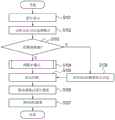
Fig. 3 is the process flow diagram that the processing of carrying out according to the digital camera of the first embodiment is shown.
Fig. 4 is the process flow diagram that the processing of the AF mode decision carrying out according to the digital camera of the first embodiment is shown.
Fig. 5 be illustrate separately in the first embodiment in order to specify the schematic diagram of example of touch operation of AF scope.
Fig. 6 be illustrate separately in the first embodiment according to the schematic diagram of example that operates the selected AF pattern of AF scope of specifying by touch.
Fig. 7 is the block diagram illustrating according to the structure of the digital camera of the second embodiment.
Fig. 8 is the process flow diagram that the processing of carrying out according to the digital camera of the second embodiment is shown.
Fig. 9 is the process flow diagram that the processing of the AE mode decision carrying out according to the digital camera of the second embodiment is shown.
Figure 10 is the block diagram illustrating according to the structure of the digital camera of the 3rd embodiment.
Figure 11 is the process flow diagram that the processing of carrying out according to the digital camera of the 3rd embodiment is shown.
Figure 12 is the process flow diagram that the processing of the colour temperature adjustment modes judgement of carrying out according to the digital camera of the 3rd embodiment is shown.
Figure 13 is the process flow diagram that the processing of AF mode decision, AE mode decision and the judgement of colour temperature adjustment modes carried out according to the digital camera of the 4th embodiment is shown.
Figure 14 illustrates the state that shows AF frame, photometric range frame and colour temperature range of value frame in the 5th embodiment as can automatically selecting independently this true result of AF pattern, AE pattern and colour temperature adjustment modes.
Embodiment
Below with reference to accompanying drawing, the preferred embodiments of the present invention are described.
the first embodiment
First, illustrate according to the primary structure of the digital camera (hereinafter referred to as camera) as picture pick-up device of the first embodiment with reference to Fig. 1 and 2.Fig. 1 is the block diagram illustrating according to the inner structure of the camera 1 of the present embodiment.Fig. 2 comprises the outside drawing of camera 1, and wherein (a) is isometric front view and (b) is rear isometric view.
On the front of camera 1, be provided with the lens unit 2 that comprises focusing lens 7.Be arranged in the inside of camera 1 and can carrying out image unit 3 imagings of focus detection and exposure tests from the light of lens unit 2 incidents.Image unit 3 makes it possible to by using the electronic shutter that charge accumulation is controlled to make a video recording, and makes it possible to export the lens image of passing through of subject image.By being presented at the display unit 4 at the back side that is disposed at camera 1 by lens image of exporting from image unit 3, make thus photographer can check composition, exposure and focal position.As shutter, can use the mechanical shutter that disposes the shading curtain that can advance in the front of image unit 3.
In the situation that photographer partly presses release-push 5 (SW1ON (connection)), utilize image unit 3 to start photometry and AF (automatic focusing), and utilize the lens driving unit 6 in lens unit 2 to drive focusing lens 7.Then,, in the situation that photographer presses release-push 5 (SW2ON) entirely, thereby advancing electronic shutter, image unit 3 makes a video recording.Then, image unit 3 starts the exposing operation of the operation that charge accumulation and electric charge read.Subsequently, captured Imagery Data Recording the set recording image in side that remains on camera 1 are read in the recording medium 9 of unit 8 interior installations.Recording medium 9 is for example general SD card or CF card.By pressing image reproducing button 10, the captured image that records and remain in recording medium 9 is presented on display unit 4.
System, control circuit 11 is circuit of controlling camera 1 entirety, comprises CPU or MPU etc., and controls following by the operation of each circuit of explanation etc.
System, control circuit 11 is as focus detecting unit 12.Starting when AF, system, control circuit 11 is based on controlling lens driving unit 6 from the output image of image unit 3, thereby on optical axis direction, drives focusing lens 7 and carry out thus focus detection.As focus detecting method, can use the known method such as shooting face phase differential AF or contrast AF method etc.In shooting face phase differential AF method, except imaging pixels, image unit 3 also comprises all unshowned focus detection pixel group and the pupil sectioned lens group who is configured in these focus detection pixel group fronts, and by utilizing phase differential to carry out focus detection to shooting face.In contrast AF method, the contrast based on captured image is recently carried out focus detection.Alternatively, can use at go forward rear drive image unit 3 and carry out swinging method of contrast AF etc. of optical axis direction.These focus detecting methods are known, therefore by the detailed description of omitting for these focus detecting methods.
System, control circuit 11 is as focus portion judging unit 29.At focus detecting unit 12, based on detecting contrast value from the output image of image unit 3, system, control circuit 11 judges the region that can focus on based on this contrast value.
System, control circuit 11 is as exposure tests unit 13.Starting when photometry, the imaging conditions that system, control circuit 11 sets in advance according to photographer, based on the electronic shutter speed of f-number and image unit 3 of determining the aperture 14 in lens unit 2 from the output image of image unit 3.Starting camera operation in the situation that by entirely pressing release-push 5 (SW2ON), system, control circuit 11 makes to expose charge accumulation time that control module 15 controls aperture 14 and electronic shutter to meet determined value.
The system, control circuit 11 control module 15 required pulse signal when using timing sequencer 16 outputs to drive image unit 3 that makes to expose.Image unit 3 carries out according to the pulse signal of exporting from timing sequencer 16 operation that charge accumulation and electric charge are read.The electric charge reading from image unit 3 is carried out digitizing and is sent to image processing circuit 18 by A/D change-over circuit 17.The image that is sent to image processing circuit 18 carries out blank level adjustment and image Compression etc. by the graphics processing unit 19 in image processing circuit 18, then reads in unit 8 by record control unit 20 via recording image and records and remain in recording medium 9.In the time pressing image reproducing button 10, recording and remain on captured image in recording medium 9 reads in unit 8 by recording image and reads in to the indicative control unit 21 in image processing circuit 18, convert analog image to by D/A change-over circuit 22, and be presented on display unit 4.
The image pickup mode selected cell 23 that is used as driver plate control member, can arrange image pickup mode.The example of the image pickup mode that can arrange comprises auto exposure mode, aperture priority exposure mode (Av), Shutter speed priority exposure mode (Tv), manual mode (M) and B door model (B).In the situation that auto exposure mode is set, photographer is by being used as the exposure setting unit 24 of driver plate control member that specific correct exposure value is set, thus and automatically definite f-number and shutter speed acquisition correct exposure in the time taking pictures.In the situation that aperture priority exposure mode (Av), Shutter speed priority exposure mode (Tv) or manual mode (M) are set, can be by specific f-number and specific shutter speed being set by f-number setting unit 25 and shutter speed setting unit 26.In the situation that B door model (B) is set, start shooting by entirely pressing release-push 5 (SW2ON), during release-push 5 is pressed (SW2ON) entirely, exposure continues, and end exposure in the situation that of being released (SW2OFF (disconnection)) at release-push 5 can be determined shutter speed thus during making a video recording.
In display unit 4, the capacitance type sensor that can detect the multiple-contact of contactant is superimposed upon for example for showing liquid crystal or the organic EL display panel of image.The viewing area that utilizes his or her finger or pen etc. (being designated hereinafter simply as " finger ") contact display unit 4 in the case of photographer, the position of this contact can be detected.In addition, utilize the viewing area of finger contact display unit 4 and make photographer and finger slides on the viewing area of display unit 4, the track of this contact can be detected.Capacitance type sensor comprises dielectric film and is configured in the electrode layer with grid pattern of this dielectric film below.Approach capacitance type sensor in the case of representing the finger of electric conductivity, electrostatic induction from electrode layer towards finger and the static capacity of dielectric film between the two occur and change.Then, be included in approaching and the variation that contacts the potential difference (PD) of decision means based on electrode layer and read static capacity in system, control circuit 11, make it possible to thus detect the position of finger.Except capacitive touch sensor, the example of touch sensor also comprises the optical type touch sensor of the variation that detects reflection of light or light and shade and detects the pressure sensitive touch sensor of the pressing force of finger.
System, control circuit 11 is as the AF scope appointed area judging unit 27 that parts are set as scope.Thereby utilize the viewing area of finger contact display unit 4 to specify AF scope in the case of photographer, the mode that system, control circuit 11 contacts according to finger arranges AF scope.For example, as shown in Fig. 5 (a), the viewing area that utilizes a finger contact display unit 4 in the case of photographer, the partial points being included in this contact portion is set to AF scope 51.As shown in Fig. 5 (b), the viewing area that utilizes two finger contact display units 4 in the case of photographer, the region that contact position by two fingers is surrounded or comprise that the region division of the contact position of these two fingers is AF scope 51.As shown in Fig. 5 (c), utilize the viewing area of a finger contact display unit 4 and make this finger slides on the viewing area of display unit 4 photographer, will be included in the region in the part of finger sliding or comprise that the region division of the part of finger sliding is AF scope 51.Except aforesaid way, specify the example of the mode of AF scope can also comprise by utilizing mode that three above fingers contacts to specify and by making to point the mode of specifying with rectangle or round-shaped slip.
System, control circuit 11 is as subject recognition unit 28 and based on identify the region corresponding with face and subject integral image from the output image of image unit 3.Known following face recognition method, wherein, in this face recognition method, the feature of the profile based on the colour of skin, face and eyes, nose etc. is extracted the facial candidate region in captured image, determines facial zone thus based on its characteristic quantity.In addition, known following method, wherein in the method, prepares multiple templates of face shape, and analyzes the correlativity between these templates and captured image, determines facial zone thus according to its correlation.About the identification of subject image, by making subject image-region and background separation extract subject image-region according to color, shape and contrast information, identify thus subject image.Be known for the method for identifying subject, therefore omitted the detailed description for the method.
According in the camera 1 of the present embodiment, can between multiple AF patterns, change AF pattern.The automatic preference pattern switch unit 30 of AF is the control members for AF pattern being changed into the AF pattern of automatic preference pattern.As shown in Figure 2, the automatic preference pattern switch unit 30 of AF can be used as dedicated operations member and is arranged on camera 1 or can be arranged in the setting option that the menu button of setting by using for changing camera 1 entirety can change.The example of AF pattern comprises face tracking AF pattern, single-point tracking AF pattern, multiple spot AF pattern and the automatic preference pattern of AF, wherein, in the automatic preference pattern of this AF, operate specified AF scope 51 according to the touch of being undertaken by photographer and automatically select AF pattern.
In face tracking AF pattern, as shown in figure below of Fig. 6 (a), subject recognition unit 28 is followed the trail of as the face of specific shot body and is carried out AF, and makes focusing lens 7 carry out AF operation.Follow the trail of in AF pattern at single-point, as shown in figure below of Fig. 6 (b), in the case of selecting a partial points of subject, subject recognition unit 28 is followed the trail of the defined part of this partial points and carries out AF, and makes focusing lens 7 carry out AF operation.In multiple spot AF pattern, as shown in figure below of Fig. 6 (c), the subject integral image that can focus on is carried out to AF, control imaging conditions such as f-number etc. so that subject integral image is focused on, and make focusing lens 7 carry out AF operation.
System, control circuit 11 is as AF mode determination 31.In the situation that utilizing the automatic preference pattern switch unit 30 of AF that the automatic preference pattern of AF is set, the judged result that the facial recognition result that system, control circuit 11 obtains according to the subject recognition unit 28 in the set AF scope 51 of AF scope appointed area judging unit 27 and focus portion judging unit 29 obtain judges AF pattern, and automatically selects this AF pattern.
The processing of carrying out according to the camera 1 of the first embodiment is described with reference to the process flow diagram of Fig. 3 and 4.The power supply of connecting camera 1 in the case of photographer, first, in step S101, system, control circuit 11 is by being presented at display unit 4 by lens image of supplying with from image unit 3.Photographer can shownly on display unit 4 check composition, exposure and focal position by lens image by checking.
The in the situation that of utilizing the automatic preference pattern switch unit 30 of AF that the automatic preference pattern of AF is set in step S102, in step S103, thereby system, control circuit 11 detect photographer whether utilized finger contact the viewing area of display unit 4 specify AF scope.
The in the situation that in step S103, photographer not utilizing finger contact viewing area, this processing enters step S108 and normally makes a video recording.That is to say, photographer detects central authorities or selects the focus point information obtaining by automatic AF frame by pressing release-push 5 (SW1ON), and this processing enters step S105, and system, control circuit 11 is presented at AF frame on display unit 4.Then,, in step S106, system, control circuit 11 makes focusing lens 7 carry out AF operation.The in the situation that in step S107, photographer pressing release-push 5 (SW2ON) entirely, make a video recording.
In step S103, the photographer viewing area that utilized finger contact in the situation that, this processing enters step S104, and AF mode determination 31 operates specified AF scope 51 according to the touch of being undertaken by photographer and judges AF pattern.
Fig. 4 illustrates the processing of the AF mode decision in step S104.Specified (step S201) AF scope 51 in the mode contacting according to above-mentioned finger, subject recognition unit 28 carries out the identification (step S202) of subject in specified AF scope 51.
Identifying (being "Yes" in step S203) identify one or more face in the situation that by subject, focus detecting unit 12 detects and facial zone α
xthe contrast value β α of the corresponding output image from image unit 3
x(step S204).Then, focus portion judging unit 29 is by detected contrast value β α in step S204
xwith predetermined threshold value β
scompare (step S205).Contrast value β α in step S205
xhigher than threshold value beta
ssituation under, focus portion judging unit 29 is judged as the facial zone that existence can focus on, and AF mode determination 31 is judged as and uses face tracking AF pattern and automatically select this face tracking AF pattern (step S206).Contrast value β α in step S205
xnot higher than threshold value beta
ssituation under, focus portion judging unit 29 is judged as and can not focuses on (step S207).As shown in Fig. 6 (c), specify wide region in the viewing area of display unit 4 as AF scope 51 in the case of photographer, in the time identifying face and can focus on, be judged as and will use face tracking AF pattern.
Do not identify (in step S203, being "No") facial in the situation that identifying by subject, focus detecting unit 12 detects the contrast value β of the output image from image unit 3 corresponding with AF scope 51
y(step S208).Then, focus portion judging unit 29 is by detected contrast value β in step S208
ywith predetermined threshold value β
scompare (step S209).In step S209, there is contrast value β
yhigher than threshold value beta
sthe situation in region under, focus portion judging unit 29 is judged as in the higher region of contrast value and can focuses on, and this processing enters step S210.In step S209, not there is not contrast value β
yhigher than threshold value beta
sthe situation in region under, focus portion judging unit 29 is judged as and can not focuses on (step S213).
In step S210, the big or small γ in the region that AF mode determination 31 can focus on
ywith predetermined threshold value γ
scompare.The big or small γ in the region that can focus in step S210
ybe greater than threshold gamma
ssituation under, AF mode determination 31 is judged as the multiple spot AF pattern and automatically selecting in this multiple spot AF pattern (step S211) of using.As shown in Fig. 6 (c), specify wide region in the viewing area of display unit 4 as AF scope 51 in the case of photographer, in the time not identifying face, be judged as and will use the multiple spot AF pattern of the region entirety that can focus in AF scope 51 being carried out to AF.
The big or small γ in the region that can focus in step S210 on the other hand,
ybe not more than threshold gamma
ssituation under, AF mode determination 31 is judged as and uses single-point to follow the trail of AF pattern and automatically select this single-point to follow the trail of AF pattern (step S212).As shown in Fig. 6 (b), utilize the viewing area of a finger contact display unit 4 and specify a partial points as AF scope 51 in the case of photographer, in the time not identifying face, be judged as and will use single-point to follow the trail of AF pattern.
Illustrate and return to now Fig. 3.In step S104, be judged as the in the situation that of will using face tracking AF pattern, as shown in Fig. 6 (a), in the facial zone that system, control circuit 11 can focus on display unit 4 in step S105, show AF frame (face detects AF frame) 61.Then,, in step S106, thereby making focusing lens 7 carry out AF operation, system, control circuit 11 focuses on the facial zone that can focus on.The in the situation that in step S107, photographer pressing release-push 5 (SW2ON) entirely, make a video recording.
In step S104, be judged as the in the situation that of will using single-point to follow the trail of AF pattern, as shown in Fig. 6 (b), the some place that system, control circuit 11 can focus on display unit 4 in step S105 shows AF frame (single-point is followed the trail of AF frame) 62.Then,, in step S106, thereby making focusing lens 7 carry out AF operation, system, control circuit 11 focuses on a point that can focus on.The in the situation that in step S107, photographer pressing release-push 5 (SW2ON) entirely, make a video recording.
In step S104, be judged as the in the situation that of will using multiple spot AF pattern, as shown in Fig. 6 (c), in step S105, system, control circuit 11 shows the AF frame (multiple spot AF frame) 63 of multiple points on display unit 4 in subject integral image.Then,, in step S106, thereby making focusing lens 7 carry out AF operation, system, control circuit 11 focuses in the subject integral image that can focus on.The in the situation that in step S107, photographer pressing release-push 5 (SW2ON) entirely, make a video recording.
As mentioned above, operate in by touch photographer in the situation that of specifying AF scope 51 on display unit 4, automatically select AF pattern according to specified AF scope 51, make it possible to thus change rapidly AF pattern.Can prevent so following problem: discharge the not free AF of change pattern when opportunity at shutter, be therefore difficult to take pictures with best AF pattern, or during changing AF pattern, missed shutter and discharge opportunity.
The invention is not restricted to above-mentioned AF pattern, and can in the scope of purport of the present invention, carry out various distortion and change.As the example of AF pattern, provide and lighted the region AF etc. that expands AF scope from a part.For example, in step S104, be judged as the in the situation that of will using single-point to follow the trail of AF pattern, in the roughly the same scope on display unit 4, again detect the multiple-contact of the finger that utilizes photographer, can be judged as and will use region AF pattern.In this case, AF frame can be lighted in turn and increase from 1 point, 5 points, 9 points and 13 according to detected frequency of exposure.
Can change the focusing pattern such as single focusing pattern and servo focusing pattern etc.Single focusing pattern is according to the fixing pattern of focus after focusing on subject from the output of focus detecting unit 12 at lens unit 2.Servo focusing pattern is to maintain by follow focus in the case of focused on subject moves the pattern that focuses on subject.For example, in step S104, thereby utilize finger contact display unit 4 to specify the subject that will focus on and under the state of finger contact display unit 4, make finger to follow the mode of the subject in mobile slides photographer, AF mode determination 31 is judged as and uses servo focusing pattern and automatically select this servo focusing pattern.Make finger leave display unit 4 and do not make finger slide on display unit 4 in the situation that, AF mode determination 31 is judged as and uses single focusing pattern and automatically select this single focusing pattern photographer.
the second embodiment
In the first embodiment, the example of automatic selection AF pattern is described; Alternatively, can automatically select AE (automatic exposure) pattern.
Illustrate according to the primary structure of the digital camera (hereinafter referred to as camera) as picture pick-up device of the second embodiment with reference to Fig. 7.Utilize identical Reference numeral to represent and the assembly identical according to the assembly of the camera 1 of the first embodiment, and omitted the explanation for these assemblies.
In a second embodiment, as shown in Figure 7, replace AF scope appointed area judging unit 27, the automatic preference pattern switch unit 30 of AF and AF mode determination 31 in the first embodiment, camera 1 comprises AE scope appointed area judging unit 32, the automatic preference pattern switch unit 33 of AE and AE mode determination 34.Identical with the automatic preference pattern switch unit 30 of AF, the automatic preference pattern switch unit 33 of AE can be used as dedicated operations member and is arranged on camera 1 or can be arranged in the setting option that the menu button of setting by using for changing camera 1 entirety can change.
In a second embodiment, system, control circuit 11 is as the AE scope appointed area judging unit 32 that parts are set as scope.Thereby utilize the viewing area of finger contact display unit 4 to specify AE scope in the case of photographer, the mode that system, control circuit 11 contacts according to this finger arranges AE scope.For example, the viewing area that utilizes a finger contact display unit 4 in the case of photographer, identical with the AF scope 51 shown in Fig. 5 (a), the partial points being included in this contact portion is set to AE scope.The viewing area that utilizes two finger contact display units 4 in the case of photographer, identical with the AF scope 51 shown in Fig. 5 (b), the region that contact position by two fingers is surrounded or comprise that the region division of the contact position of these two fingers is AE scope.Utilize the viewing area of a finger contact display unit 4 and make this finger slides on the viewing area of display unit 4 photographer, identical with the AF scope 51 shown in Fig. 5 (c), by region included in the part of finger sliding or comprise that the region division of the part of finger sliding is AE scope.Except aforesaid way, specify the example of the mode of AE scope can also comprise by utilizing mode that three above fingers contacts to specify and by making to point the mode of specifying with rectangle or round-shaped slip.
System, control circuit 11 is as AE mode determination 34.In the situation that utilizing the automatic preference pattern switch unit 33 of AE that the automatic preference pattern of AE is set, the judged result that the facial recognition result that system, control circuit 11 obtains according to the subject recognition unit 28 within the scope of the set AE of AE scope appointed area judging unit 32 and focus portion judging unit 29 obtain judges AE pattern, and automatically selects this AE pattern.In the present embodiment, the example of the AE pattern judging in the automatic preference pattern of AE comprises that face tracking metering mode, single-point are followed the trail of metering mode and subject is evaluated metering mode, wherein: in this face tracking metering mode, subject recognition unit 28 is followed the trail of the face of subject and carried out photometry; Follow the trail of in metering mode at this single-point, subject recognition unit 28 is followed the trail of a partial points of subject and is carried out photometry; And evaluate in metering mode in this subject, subject entirety is carried out to photometry.Exposure tests unit 13 is from the output detections monochrome information from image unit 3, and carries out photometry.
The processing of carrying out according to the camera 1 of the second embodiment is described with reference to the process flow diagram of Fig. 8 and 9.The power supply of connecting camera 1 in the case of photographer, first, in step S301, system, control circuit 11 is by being presented at display unit 4 by lens image of supplying with from image unit 3.Photographer can shownly on display unit 4 check composition, exposure and focal position by lens image by checking.
The in the situation that of utilizing the automatic preference pattern switch unit 33 of AE that the automatic preference pattern of AE is set in step S302, in step S203, thereby system, control circuit 11 detect photographer whether utilized finger contact the viewing area of display unit 4 specify AE scope.
The in the situation that in step S303, photographer not utilizing finger contact viewing area, this processing enters step S308 and normally makes a video recording.That is to say, photographer detects specific photometry information by pressing release-push 5 (SW1ON), and this processing enters step S305, and system, control circuit 11 is presented at photometric range frame on display unit 4.Then, in step S306, carry out AE operation.The in the situation that in step S307, photographer pressing release-push 5 (SW2ON) entirely, make a video recording.
In step S303, the photographer viewing area that utilized finger contact in the situation that, this processing enters step S304, and AE mode determination 34 operates specified AE scope according to the touch of being undertaken by photographer and judges AE pattern.
Fig. 9 illustrates the processing of the AE mode decision in step S304.Utilize identical Reference numeral to represent the processing identical with processing in the process flow diagram of the Fig. 4 described in the first embodiment, and omitted the explanation for these processing.Specify (step S401) AE scope in the mode contacting according to above-mentioned finger, carry out the judgement of step S202~S202 and step S208~S210.Contrast value β α in step S205
xhigher than threshold value beta
ssituation under, be judged as the facial zone that existence can focus on, and AE mode determination 34 is judged as the face tracking AE pattern and automatically select this face tracking AE pattern (step S402) of using.The big or small γ in the region that can focus in step S210
ybe greater than threshold gamma
ssituation under, AE mode determination 34 is judged as and uses subject to evaluate AE pattern and automatically select this subject to evaluate AE pattern (step S403).The big or small γ in the region that can focus in step S210 on the other hand,
ybe not more than threshold gamma
ssituation under, AE mode determination 34 is judged as and uses single-point to follow the trail of AE pattern and automatically select this single-point to follow the trail of AE pattern (step S404).
Explanation now will be back to Fig. 8.In step S304, be judged as the in the situation that of will using face tracking AE pattern, identical with (face detects AF frame) 61 of the AF frame shown in Fig. 6 (a), in the facial zone that system, control circuit 11 can focus on display unit 4 in step S305, show photometric range frame.Then, in step S306, the facial zone that can focus on is carried out to AE operation.The in the situation that in step S307, photographer pressing release-push 5 (SW2ON) entirely, make a video recording.
In step S304, be judged as the in the situation that of will using single-point to follow the trail of AE pattern, identical with (single-point is followed the trail of AE frame) 62 of the AF frame shown in Fig. 6 (b), the some place that system, control circuit 11 can focus on display unit 4 in step S305 shows photometric range frame.Then, in step S306, can focus on point is carried out to AE operation.The in the situation that in step S307, photographer pressing release-push 5 (SW2ON) entirely, make a video recording.
In step S304, be judged as the in the situation that of will using subject to evaluate AE pattern, identical with (the multiple spot AF frame) 63 of the AF frame shown in Fig. 6 (c), in step S305, system, control circuit 11 shows the photometric range frame of multiple points on display unit 4 in subject integral image.Then, in step S306, the subject integral image that can focus on is carried out to AE operation.The in the situation that in step S307, photographer pressing release-push 5 (SW2ON) entirely, make a video recording.
the 3rd embodiment
The example of the automatic selection AE pattern in example and second embodiment of the automatic selection AF pattern in the first embodiment has been described; Alternatively, can automatically select colour temperature adjustment modes.
Illustrate according to the primary structure of the digital camera (hereinafter referred to as camera) as picture pick-up device of the 3rd embodiment with reference to Figure 10.Utilize identical Reference numeral to represent and the assembly identical according to the assembly of the camera 1 of the first embodiment, and omitted the explanation for these assemblies.
In the 3rd embodiment, as shown in figure 10, replace AF scope appointed area judging unit 27, the automatic preference pattern switch unit 30 of AF and AF mode determination 31 in the first embodiment, camera 1 comprises colour temperature range of value appointed area judging unit 35, the automatic preference pattern switch unit 36 of colour temperature adjustment and colour temperature adjustment modes judging unit 37.Identical with the automatic preference pattern switch unit 33 of AE with the automatic preference pattern switch unit 30 of AF, the automatic preference pattern switch unit 36 of colour temperature adjustment can be used as dedicated operations member and is arranged on camera 1 or can be arranged in the setting option that the menu button of setting by using for changing camera 1 entirety can change.
In the 3rd embodiment, system, control circuit 11 is as the colour temperature range of value appointed area judging unit 35 that parts are set as scope.Thereby utilize the viewing area of finger contact display unit 4 to specify colour temperature range of value in the case of photographer, the mode that system, control circuit 11 contacts according to finger arranges colour temperature range of value.For example, the viewing area that utilizes a finger contact display unit 4 in the case of photographer, identical with the AF scope 51 shown in Fig. 5 (a), a partial points included in this contact portion is set to colour temperature range of value.The viewing area that utilizes two finger contact display units 4 in the case of photographer, identical with the AF scope 51 shown in Fig. 5 (b), the region that contact position by two fingers is surrounded or comprise that the region division of the contact position of these two fingers is colour temperature range of value.Utilize the viewing area of a finger contact display unit 4 and make this finger slides on the viewing area of display unit 4 photographer, identical with the AF scope 51 shown in Fig. 5 (c), by region included in the part of finger sliding or comprise that the region division of the part of finger sliding is colour temperature range of value.Except aforesaid way, specify the example of the mode of colour temperature range of value can also comprise by utilizing mode that three above fingers contacts to specify and by making to point the mode of specifying with rectangle or round-shaped slip.
System, control circuit 11 is as colour temperature adjustment modes judging unit 37.In the situation that utilizing the automatic preference pattern switch unit 36 of colour temperature adjustment that the automatic preference pattern of colour temperature adjustment is set, the judged result that the facial recognition result that system, control circuit 11 obtains according to the subject recognition unit 28 in the set colour temperature range of value of colour temperature range of value appointed area judging unit 35 and focus portion judging unit 29 obtain judges colour temperature adjustment modes, and automatically selects this colour temperature adjustment modes.In the present embodiment, the example of the colour temperature adjustment modes judging in the automatic preference pattern of colour temperature adjustment comprises face tracking colour temperature adjustment modes, light source color temperature adjustment modes and automatic colour temperature adjustment modes, wherein: in this face tracking colour temperature adjustment modes, subject recognition unit 28 is followed the trail of the face of subject and adjusted colour temperature according to the color of skin; In this light source color temperature adjustment modes, the light source that exposure tests unit 13 sensed luminance are high and adjust colour temperature according to the color of light source; And in this automatic colour temperature adjustment modes, adjust colour temperature according to the colour temperature on a rough average of subject entirety.Colour temperature is evaluated and adjusted to image processing circuit 18 according to the colouring information of the output from image unit 3.
The processing of carrying out according to the camera 1 of the 3rd embodiment is described with reference to the process flow diagram of Figure 11 and 12.The power supply of connecting camera 1 in the case of photographer, first, in step S501, system, control circuit 11 is by being presented at display unit 4 by lens image of supplying with from image unit 3.Photographer can shownly on display unit 4 check composition, exposure and focal position by lens image by checking.
The in the situation that of utilizing the automatic preference pattern switch unit 36 of colour temperature adjustment that the automatic preference pattern of colour temperature adjustment is set in step S502, in step S503, thus system, control circuit 11 detect photographer whether utilized finger contact the viewing area of display unit 4 specify colour temperature range of value.
The in the situation that in step S503, photographer not utilizing finger contact viewing area, this processing enters step S508 and normally makes a video recording.That is to say, photographer detects specific color temperature information by pressing release-push 5 (SW1ON), and this processing enters step S505, and system, control circuit 11 is presented at colour temperature range of value frame on display unit 4.Then, in step S506, carry out colour temperature adjustment operation.The in the situation that in step S507, photographer pressing release-push 5 (SW2ON) entirely, make a video recording.
In step S503 the photographer viewing area that utilized finger contact in the situation that, this processing enters step S504, and colour temperature adjustment modes judging unit 37 operates specified colour temperature range of value according to the touch of being undertaken by photographer and judges colour temperature adjustment modes.
Figure 12 illustrates the processing of the colour temperature adjustment modes judgement in step S504.Utilize identical Reference numeral to represent the processing identical with processing in the process flow diagram of the Fig. 4 described in the first embodiment, and omitted the explanation for these processing.Specify (step S601) colour temperature range of value in the mode contacting according to above-mentioned finger, carry out the judgement of step S202~S205 and step S208 and S209.Contrast value β α in step S205
xhigher than threshold value beta
ssituation under, be judged as the facial zone that existence can focus on, and colour temperature adjustment modes judging unit 37 is judged as and uses face tracking colour temperature adjustment modes and automatically select this face tracking colour temperature adjustment modes (step S602).
In step S209, there is contrast value β
yhigher than threshold value beta
sthe situation in region under, is judged as in the higher region of contrast value and can focuses on, and this processing enters step S603.In step S603, the brightness δ α in the region that colour temperature adjustment modes judging unit 37 can focus on and predetermined threshold value δ
scompare.The brightness δ α in the region that can focus in step S603 is higher than threshold value δ
ssituation under, colour temperature adjustment modes judging unit 37 is judged as and uses light source color temperature adjustment modes and automatically select this light source color temperature adjustment modes (step S604).The brightness δ α in the region that can focus in step S603 on the other hand, is not higher than threshold value δ
ssituation under, colour temperature adjustment modes judging unit 37 is judged as and uses automatic colour temperature adjustment modes and automatically select this automatic colour temperature adjustment modes (step S605).
Explanation now will be back to Figure 11.In step S504, be judged as the in the situation that of will using face tracking colour temperature adjustment modes, identical with (face detects AF frame) 61 of the AF frame shown in Fig. 6 (a), in the facial zone that system, control circuit 11 can focus on display unit 4, show colour temperature range of value frame.Then,, in step S506, the facial zone that can focus on is carried out colour temperature evaluation and carries out colour temperature adjustment operation.The in the situation that in step S507, photographer pressing release-push 5 (SW2ON) entirely, make a video recording.
In step S504, be judged as the in the situation that of will using automatic colour temperature adjustment modes, in step S505, thereby system, control circuit 11 expands colour temperature range of value in subject entirety, colour temperature photometric range frame be presented on display unit 4.Then,, in step S506, detect the colour temperature on a rough average of subject in colour temperature range of value frame and carry out colour temperature adjustment operation.The in the situation that in step S507, photographer pressing release-push 5 (SW2ON) entirely, make a video recording.
In step S504, be judged as the in the situation that of will using light source color temperature adjustment modes, in step S505, exposure tests unit 13 detects the colour temperature of the high light source portion of brightness in colour temperature range of value, and system, control circuit 11 is presented at colour temperature photometric range frame on display unit 4.Then, in step S506, carry out colour temperature adjustment operation.The in the situation that in step S507, photographer pressing release-push 5 (SW2ON) entirely, make a video recording.
the 4th embodiment
The example of the automatic selection colour temperature adjustment modes in example and the 3rd embodiment of the automatic selection AE pattern in example, second embodiment of the automatic selection AF pattern in the first embodiment has been described; Alternatively, can make these operate interlock each other.
For example, as shown in figure 13, identical with the first embodiment, judgement also selects face tracking AF pattern, multiple spot AF pattern or single-point to follow the trail of AF pattern (step S201~step S212) automatically.
Then, the in the situation that of automatically selecting face tracking AF pattern, automatically select face tracking AE pattern (step S402) in step S206, wherein in this face tracking AE pattern, the facial zone that can focus on is as photometric range frame.In addition, automatically select face tracking colour temperature adjustment modes (step S602), wherein, in this face tracking colour temperature adjustment modes, the facial zone that can focus on is as colour temperature range of value frame.
On the other hand, automatically the in the situation that of selecting multiple spot AF pattern in step S211, automatically select subject to evaluate AE pattern (step S403), wherein evaluate in AE pattern in this subject, the photometric range frame of multiple points is set in subject integral image.Automatically the in the situation that of selecting single-point to follow the trail of AF pattern in step S212, automatically select single-point to follow the trail of AE pattern (step S404), wherein follow the trail of in AE pattern at this single-point, a point that can focus on is as photometric range frame.
Then,, in the situation that automatically selecting subject to evaluate AE pattern and single-point tracking AE pattern, this processing enters step S603, and the brightness δ α in the region that can focus on and predetermined threshold value δ
scompare.The brightness δ α in the region that can focus in step S603 is higher than threshold value δ
ssituation under, be judged as and will use light source color temperature adjustment modes and automatically select this light source color temperature adjustment modes (step S604).At the brightness δ in the region that can focus on α not higher than threshold value δ
ssituation under, be judged as and will use automatic colour temperature adjustment modes and automatically select this automatic colour temperature adjustment modes (step S605).
the 5th embodiment
In the 4th embodiment, the example of also automatically selecting linkedly AE pattern and colour temperature adjustment modes with the automatic selection of AF pattern is described; Alternatively, in sequence of operations, can automatically select independently AF pattern, AE pattern and colour temperature adjustment modes.
In the present embodiment, in order automatically to select independently AF pattern, AE pattern and colour temperature adjustment modes in sequence of operations, system, control circuit 11 is equipped with the function as engagement sequence detection part, and wherein this engagement sequence detection part detects the order of contact for utilize finger multiple-contact display unit 4 photographer in the situation that.
In the present embodiment, with reference to Fig. 3 and 8, the example of automatically selecting independently successively in order AF pattern and AE pattern is described.
By being presented at by lens image the state of display unit 4 of supplying with from image unit 3, check whether finger has contacted the viewing area (the step S103 of Fig. 3) of display unit 4.In the case of the contact that finger detected, carry out step S104, the S105 of Fig. 3 and the processing of S106.
Subsequently, entirely press release-push 5 (SW2ON) before photographer, detect under given conditions and point the viewing area (the step S303 of Fig. 8) that whether has contacted display unit 4.In the case of the contact that finger detected, carry out step S304, the S305 of Fig. 8 and the processing of S306.As specified conditions, for example, can be the condition of carrying out the contact (step S503) of another finger under the state of the contact that still maintains primary finger (step S103).In addition, can be after having carried out the contact for the first time (step S103) of finger and having discharged this contact, the condition of carrying out the contact for the second time (step S503) of this finger in special time period.
Afterwards, in the situation that photographer presses release-push 5 (SW2ON) entirely, make a video recording.
In the present embodiment, the example of automatically selecting independently AF pattern and AE pattern has been described; Alternatively, can automatically select independently any combination of AF pattern, AE pattern and colour temperature adjustment modes.For example can in menu setting, change the order of automatically selecting.
Figure 14 illustrates the state that shows AF frame, photometric range frame and colour temperature range of value frame as can automatically selecting independently this true result of AF pattern, AE pattern and colour temperature adjustment modes.
the 6th embodiment
As described in the first embodiment and as shown in Fig. 5 (a), the viewing area that utilizes a finger contact display unit 4 in the case of photographer, a partial points included in this contact portion is set to AF scope 51.Now, system, control circuit 11 detects T duration of contact.
Subsequently, in the situation that making focusing lens 7 carry out AF operation (step S106), according to duration of contact, T arranges until the driving time that focusing lens 7 focuses on.For example,, until the driving time that focusing lens 7 focuses on is set to T duration of contact.
In the present embodiment, illustrated that AF pattern is as example; But the present embodiment also can be applicable to the automatic selection of AE pattern and colour temperature adjustment modes.In the situation that automatically selecting AE pattern, according to duration of contact, T arranges the change time of the exposure of the image unit 3 that exposure control module 15 controls, and carries out photometry.In the situation that automatically selecting colour temperature adjustment modes, according to duration of contact, T arranges colour temperature adjustment (change) time that image processing circuit 18 is controlled, and adjusts the colour temperature from the output image of image unit 3.
As in this embodiment, according to duration of contact, T arranges until the driving time that focusing lens 7 focuses on, and for example in the situation that of taking moving image, makes user can easily control the slow focusing as animation thus.
The preferred embodiments of the present invention have more than been described; But, the invention is not restricted to these embodiment, and can in the scope of purport of the present invention, carry out various distortion and change.
other embodiment
Can also realize the present invention by carrying out following processing: the software (program) of the function that realizes above-described embodiment is supplied to system or equipment via network or various storage medium, and the computing machine of this system or equipment (CPU or MPU etc.) reads and carry out this program.
In addition, in the above-described embodiments, as the example of correction processing of the output that uses focus detection pixel, crosstalk correction processing is described, still, has proofreaied and correct based on abnormal output the problem of processing and be not limited to occur in crosstalk correction processing.In addition, above-mentioned feature also may be applicable to carry out other and proofread and correct situation about processing.So, should be not crosstalk correction processing by scope of application limited interpretation of the present invention.
In addition, in the above-described embodiments, illustrated that CPU121 carries out the structure of processing with software mode.But at least a portion processing in these processing can be carried out by hardware (ASIC, FPGA (Field Programmable Gate Array) etc.).
The invention is not restricted to above-described embodiment, and can in the situation that not deviating from the spirit and scope of the present invention, carry out various changes and distortion.Therefore,, for open scope of the present invention, appended following claim.
The application requires the Japanese patent application 2011-225264 submitting on October 12nd, 2011 and the right of priority of Japanese patent application 2012-205997 of submitting on September 19th, 2012, comprises by reference the full content of these two applications at this.
Claims (16)
1. a picture pick-up device, comprising:
Display unit, for showing the output image from the shooting part in order to take subject image, and can detect the multiple-contact of contactant;
Focus detection parts, carry out focus detection for the output image based on from described shooting part;
Focus portion decision means, for based on judge the region that can focus on from the output of described focus detection parts;
Subject identification component, for based on identifying predetermined subject from the output image of described shooting part; And
Mode decision parts, for according to contactant and described display unit contact carry out following automatic selection at least any is selected automatically: from multiple automatic focusing patterns, automatically select automatic focusing pattern, from multiple auto exposure modes, automatically select auto exposure mode and from multiple colour temperature adjustment modes, automatically select colour temperature adjustment modes.
2. picture pick-up device according to claim 1, wherein, also comprises:
Scope arranges parts, for according to contactant and described display unit contact to arrange scope,
Wherein, described mode decision parts arrange the recognition result of the predetermined subject that the described subject identification component in the set scope of parts obtains and the judged result that described focus portion decision means obtains according to described scope, automatically select.
3. picture pick-up device according to claim 2, wherein, in the situation that a contactant contacts described display unit, described scope arranges a partial points included in the contact position of the described contactant of parts and is set to scope.
4. according to the picture pick-up device described in claim 2 or 3, wherein, in the situation that multiple contactants contact described display unit, it is scope by the region being surrounded by multiple contact positions of described multiple contactants or the region division that comprises described multiple contact positions that described scope arranges parts.
5. according to the picture pick-up device described in any one in claim 2 to 4, wherein, in the situation that contactant contacts described display unit and slide on described display unit, described scope arranges parts by region included in the part of this contactant slip or comprises that the region division of the part of this contactant slip is scope.
6. according to the picture pick-up device described in any one in claim 2 to 5, wherein, described mode decision parts are as automatic focusing mode decision parts, and in described scope, subject identification component described in the set scope of parts is set and identifies predetermined subject, described mode decision parts select to follow the trail of the predetermined subject that can focus on the tracking automatic focusing pattern of carrying out automatic focusing automatically.
7. according to the picture pick-up device described in any one in claim 2 to 6, wherein, described mode decision parts are as automatic focusing mode decision parts, and in described scope, subject identification component described in the set scope of parts being set does not identify predetermined subject, described mode decision parts proceed as follows: the size in the region that can focus on of judging in described focus portion decision means is greater than predetermined threshold, and described mode decision parts select subject integral image to carry out the multiple spot automatic focusing pattern of automatic focusing automatically; And the size in the region that can focus on of judging in described focus portion decision means is not more than described predetermined threshold, described mode decision parts select the single-point of following the trail of a partial points of subject and carrying out automatic focusing to follow the trail of automatic focusing pattern automatically.
8. picture pick-up device according to claim 7, wherein, in the situation that described mode decision parts are judged as the described single-point tracking of use automatic focusing pattern, while the multiple-contact of contactant again being detected in roughly the same scope on described display unit, be judged as and will use region automatic focusing pattern, and expand according to the number of times of detected contact the automatic focusing frame being presented on described display unit.
9. picture pick-up device according to claim 1, wherein,
Described mode decision parts are as automatic focusing mode decision parts, and described mode decision parts are selected single focusing pattern and servo focusing pattern automatically, wherein in described single focusing pattern, after subject is focused on, focus is fixed, and in described servo focusing pattern, in the case of focused on subject moves, by making focus follow to maintain to focus on subject, and
Make contactant contact described display unit with the state of specifying the subject that will focus on and contact described display unit at this contactant under to follow the mode of just mobile subject slides, described mode decision parts are selected described servo focusing pattern automatically, and do not slide and leave described display unit in the situation that, described mode decision parts are selected described single focusing pattern automatically at contactant.
10. according to the picture pick-up device described in any one in claim 2 to 5, wherein, described mode decision parts are as auto exposure mode decision means, and in described scope, subject identification component described in the set scope of parts is set and identifies predetermined subject, described mode decision parts select to follow the trail of the predetermined subject that can focus on the tracking auto exposure mode that carries out automatic exposure automatically.
11. according to the picture pick-up device described in any one in claim 2 to 5 and 10, wherein, described mode decision parts are as auto exposure mode decision means, and in described scope, subject identification component described in the set scope of parts being set does not identify predetermined subject, described mode decision parts proceed as follows: the size in the region that can focus on of judging in described focus portion decision means is greater than predetermined threshold, described mode decision parts select the subject of subject integral image being carried out to automatic exposure to evaluate auto exposure mode automatically, and the size in the region that can focus on of judging in described focus portion decision means is not more than described predetermined threshold, described mode decision parts select the single-point of following the trail of a partial points of subject and carrying out automatic exposure to follow the trail of auto exposure mode automatically.
12. according to the picture pick-up device described in any one in claim 2 to 5, wherein, described mode decision parts are as colour temperature adjustment modes decision means, and in described scope, subject identification component described in the set scope of parts is set and identifies predetermined subject, described mode decision parts select to follow the trail of the go forward side by side tracking colour temperature adjustment modes of circumstances in which people get things ready for a trip temperature adjustment of the predetermined subject that can focus on automatically.
13. according to the picture pick-up device described in any one in claim 2 to 5 and 12, wherein, described mode decision parts are as colour temperature adjustment modes decision means, and in described scope, subject identification component described in the set scope of parts being set does not identify predetermined subject, described mode decision parts proceed as follows: the brightness in the region that can focus on of judging in described focus portion decision means is higher than predetermined threshold, the light source color temperature adjustment modes that described mode decision parts are automatically selected to detect the light source of high brightness and adjusted colour temperature according to the color of described light source, and the brightness in the region that can focus on of judging in described focus portion decision means is higher than described predetermined threshold, described mode decision parts select to adjust according to the colour temperature on a rough average of subject entirety the automatic colour temperature adjustment modes of colour temperature automatically.
14. according to the picture pick-up device described in any one in claim 1 to 13, and wherein, the contrast value of described focus portion decision means based on the detected output image from described shooting part of described focus detection parts, judges the region that can focus on.
The control method of 15. 1 kinds of picture pick-up devices, described picture pick-up device comprises display unit, described display unit is for showing from the output image of the shooting part in order to take subject image and can detecting the multiple-contact of contactant, and described control method comprises the following steps:
Focus detection step, carries out focus detection for the output image based on from described shooting part;
Focus portion determining step, judges the region that can focus on for the output based on described focus detection step;
Subject identification step, for based on identifying predetermined subject from the output image of described shooting part; And
Mode decision step, for according to contactant and described display unit contact carry out following automatic selection at least any is selected automatically: from multiple automatic focusing patterns, automatically select automatic focusing pattern, from multiple auto exposure modes, automatically select auto exposure mode and from multiple colour temperature adjustment modes, automatically select colour temperature adjustment modes.
16. 1 kinds for controlling the program of picture pick-up device, described picture pick-up device comprises display unit, described display unit is for showing from the output image of the shooting part in order to take subject image and can detecting the multiple-contact of contactant, and described program is used as with lower member computing machine:
Focus detection parts, carry out focus detection for the output image based on from described shooting part;
Focus portion decision means, for based on judge the region that can focus on from the output of described focus detection parts;
Subject identification component, for based on identifying predetermined subject from the output image of described shooting part; And
Mode decision parts, for according to contactant and described display unit contact carry out following automatic selection at least any is selected automatically: from multiple automatic focusing patterns, automatically select automatic focusing pattern, from multiple auto exposure modes, automatically select auto exposure mode and from multiple colour temperature adjustment modes, automatically select colour temperature adjustment modes.
Applications Claiming Priority (5)
| Application Number | Priority Date | Filing Date | Title |
|---|---|---|---|
| JP2011225264 | 2011-10-12 | ||
| JP2011-225264 | 2011-10-12 | ||
| JP2012205997A JP6083987B2 (en) | 2011-10-12 | 2012-09-19 | Imaging apparatus, control method thereof, and program |
| JP2012-205997 | 2012-09-19 | ||
| PCT/JP2012/075762 WO2013054726A1 (en) | 2011-10-12 | 2012-10-04 | Imaging device, and method and program for controlling same |
Publications (2)
| Publication Number | Publication Date |
|---|---|
| CN103858043A true CN103858043A (en) | 2014-06-11 |
| CN103858043B CN103858043B (en) | 2017-11-28 |
Family
ID=48081782
Family Applications (1)
| Application Number | Title | Priority Date | Filing Date |
|---|---|---|---|
| CN201280050338.7A Active CN103858043B (en) | 2011-10-12 | 2012-10-04 | Picture pick-up device and its control method |
Country Status (5)
| Country | Link |
|---|---|
| US (1) | US20130155276A1 (en) |
| JP (1) | JP6083987B2 (en) |
| CN (1) | CN103858043B (en) |
| TW (1) | TWI549501B (en) |
| WO (1) | WO2013054726A1 (en) |
Cited By (9)
| Publication number | Priority date | Publication date | Assignee | Title |
|---|---|---|---|---|
| CN104219518A (en) * | 2014-07-31 | 2014-12-17 | 小米科技有限责任公司 | Photometry method and device |
| CN104320654A (en) * | 2014-10-28 | 2015-01-28 | 小米科技有限责任公司 | Light metering method and device |
| CN105827994A (en) * | 2016-04-12 | 2016-08-03 | 乐视控股(北京)有限公司 | System and method for solving problem of focusing area overexposure |
| US9674454B2 (en) | 2014-07-31 | 2017-06-06 | Xiaomi Inc. | Light metering methods and devices |
| WO2017166076A1 (en) * | 2016-03-29 | 2017-10-05 | 华为技术有限公司 | Method, device and apparatus for determining focus window |
| CN107736009A (en) * | 2015-06-16 | 2018-02-23 | 奥林巴斯株式会社 | Operation method, operation program and filming apparatus |
| CN109074222A (en) * | 2016-04-19 | 2018-12-21 | 麦克赛尔株式会社 | Mobile terminal apparatus |
| CN110062155A (en) * | 2019-03-25 | 2019-07-26 | 成都品果科技有限公司 | A kind of portrait based on automatic light measuring is taken pictures optimization system, method and apparatus |
| CN110741627A (en) * | 2017-06-21 | 2020-01-31 | 富士胶片株式会社 | Imaging device, method for controlling imaging device, and program for controlling imaging device |
Families Citing this family (23)
| Publication number | Priority date | Publication date | Assignee | Title |
|---|---|---|---|---|
| JP5949306B2 (en) * | 2012-08-13 | 2016-07-06 | 株式会社ニコン | Image processing apparatus, imaging apparatus, and image processing program |
| KR101918760B1 (en) * | 2012-10-30 | 2018-11-15 | 삼성전자주식회사 | Imaging apparatus and control method |
| JP5949591B2 (en) * | 2013-02-13 | 2016-07-06 | ソニー株式会社 | Imaging apparatus, control method, and program |
| KR102034583B1 (en) * | 2013-02-28 | 2019-10-21 | 엘지전자 주식회사 | Digital device and method for controlling the same |
| JP2015032640A (en) | 2013-07-31 | 2015-02-16 | 株式会社東芝 | Solid-state imaging apparatus, and manufacturing method of solid-state imaging apparatus |
| JP6164978B2 (en) * | 2013-08-21 | 2017-07-19 | キヤノン株式会社 | FOCUS ADJUSTMENT DEVICE, ITS CONTROL METHOD, CONTROL PROGRAM, AND IMAGING DEVICE |
| CN103841390B (en) * | 2014-02-22 | 2015-06-17 | 深圳市中兴移动通信有限公司 | Shooting method and device |
| TWI524251B (en) | 2014-02-24 | 2016-03-01 | 原相科技股份有限公司 | Capacitive finger navigation module and manufacturing method thereof |
| US9203951B1 (en) * | 2014-07-03 | 2015-12-01 | International Business Machines Corporation | Mobile telephone adapted for use with one hand |
| JP6512810B2 (en) * | 2014-12-11 | 2019-05-15 | キヤノン株式会社 | Image pickup apparatus, control method and program |
| JP2016126237A (en) * | 2015-01-07 | 2016-07-11 | キヤノン株式会社 | Focus adjustment device and control method of the same |
| KR102328098B1 (en) * | 2015-02-13 | 2021-11-17 | 삼성전자주식회사 | Apparatus and method for focusing of carmea device or an electronic device having a camera module |
| CN106101680B (en) * | 2015-05-06 | 2018-12-25 | 小米科技有限责任公司 | Acquisition parameters setting method and device |
| JP6443842B2 (en) * | 2015-06-19 | 2018-12-26 | パナソニックIpマネジメント株式会社 | Face detection device, face detection system, and face detection method |
| KR102429427B1 (en) * | 2015-07-20 | 2022-08-04 | 삼성전자주식회사 | Image capturing apparatus and method for the same |
| US9838594B2 (en) | 2016-03-02 | 2017-12-05 | Qualcomm Incorporated | Irregular-region based automatic image correction |
| JP6623916B2 (en) * | 2016-04-26 | 2019-12-25 | リコーイメージング株式会社 | Imaging device |
| JP6833535B2 (en) * | 2017-02-03 | 2021-02-24 | キヤノン株式会社 | Imaging device, control method and program of imaging device |
| JP7009096B2 (en) * | 2017-07-06 | 2022-01-25 | キヤノン株式会社 | Electronic devices and their control methods |
| CN107801012B (en) * | 2017-10-30 | 2019-05-17 | Oppo广东移动通信有限公司 | White balancing treatment method and device, electronic device and computer readable storage medium |
| JP6617765B2 (en) * | 2017-12-14 | 2019-12-11 | 株式会社ニコン | Imaging device |
| JP2018173632A (en) * | 2018-03-22 | 2018-11-08 | 株式会社ニコン | Imaging device |
| WO2022118259A1 (en) * | 2020-12-03 | 2022-06-09 | Adasky, Ltd. | Lens clearing arrangement |
Citations (7)
| Publication number | Priority date | Publication date | Assignee | Title |
|---|---|---|---|---|
| US20020106206A1 (en) * | 2001-01-15 | 2002-08-08 | Nikon Corporation | Image-capturing device |
| JP2004117490A (en) * | 2002-09-24 | 2004-04-15 | Fuji Photo Optical Co Ltd | Autofocus system |
| JP2004205885A (en) * | 2002-12-26 | 2004-07-22 | Sony Corp | Imaging unit and method, and program |
| US20090019399A1 (en) * | 2007-07-10 | 2009-01-15 | Brother Kogyo Kabushiki Kaisha | Image displaying device, and method and computer readable medium for the same |
| CN101605209A (en) * | 2008-05-26 | 2009-12-16 | 三洋电机株式会社 | Camera head and image-reproducing apparatus |
| JP2011030008A (en) * | 2009-07-27 | 2011-02-10 | Canon Inc | Imaging apparatus |
| JP2011035765A (en) * | 2009-08-04 | 2011-02-17 | Canon Inc | Image processing apparatus and method |
Family Cites Families (15)
| Publication number | Priority date | Publication date | Assignee | Title |
|---|---|---|---|---|
| JP3709294B2 (en) * | 1998-11-18 | 2005-10-26 | 株式会社リコー | Automatic focus detection device |
| JP2001203928A (en) * | 2000-01-20 | 2001-07-27 | Minolta Co Ltd | Digital camera |
| JP4029206B2 (en) * | 2001-01-15 | 2008-01-09 | 株式会社ニコン | Imaging device |
| JP2005244311A (en) * | 2004-02-24 | 2005-09-08 | Canon Inc | Imaging unit, control method of imaging unit, and control program |
| JP4759329B2 (en) * | 2005-06-23 | 2011-08-31 | Hoya株式会社 | Imaging device having autofocus function |
| US8089515B2 (en) * | 2005-12-30 | 2012-01-03 | Nokia Corporation | Method and device for controlling auto focusing of a video camera by tracking a region-of-interest |
| JP2009010777A (en) * | 2007-06-28 | 2009-01-15 | Sony Corp | Imaging device, photography control method, and program |
| JP2009157123A (en) * | 2007-12-27 | 2009-07-16 | Eastman Kodak Co | Imaging device |
| JP4530067B2 (en) * | 2008-03-27 | 2010-08-25 | ソニー株式会社 | Imaging apparatus, imaging method, and program |
| US8237807B2 (en) * | 2008-07-24 | 2012-08-07 | Apple Inc. | Image capturing device with touch screen for adjusting camera settings |
| JP2010062825A (en) * | 2008-09-03 | 2010-03-18 | Ricoh Co Ltd | Imaging device and method of controlling imaging |
| US8243188B2 (en) * | 2008-10-30 | 2012-08-14 | Olympus Imaging Corp. | Imaging apparatus |
| JP5407380B2 (en) * | 2009-02-03 | 2014-02-05 | 富士通モバイルコミュニケーションズ株式会社 | Mobile terminal with imaging function |
| US9182854B2 (en) * | 2009-07-08 | 2015-11-10 | Microsoft Technology Licensing, Llc | System and method for multi-touch interactions with a touch sensitive screen |
| US20120120277A1 (en) * | 2010-11-16 | 2012-05-17 | Apple Inc. | Multi-point Touch Focus |
-
2012
- 2012-09-19 JP JP2012205997A patent/JP6083987B2/en not_active Expired - Fee Related
- 2012-10-04 WO PCT/JP2012/075762 patent/WO2013054726A1/en active Application Filing
- 2012-10-04 CN CN201280050338.7A patent/CN103858043B/en active Active
- 2012-10-11 TW TW101137448A patent/TWI549501B/en active
-
2013
- 2013-02-07 US US13/762,120 patent/US20130155276A1/en not_active Abandoned
Patent Citations (7)
| Publication number | Priority date | Publication date | Assignee | Title |
|---|---|---|---|---|
| US20020106206A1 (en) * | 2001-01-15 | 2002-08-08 | Nikon Corporation | Image-capturing device |
| JP2004117490A (en) * | 2002-09-24 | 2004-04-15 | Fuji Photo Optical Co Ltd | Autofocus system |
| JP2004205885A (en) * | 2002-12-26 | 2004-07-22 | Sony Corp | Imaging unit and method, and program |
| US20090019399A1 (en) * | 2007-07-10 | 2009-01-15 | Brother Kogyo Kabushiki Kaisha | Image displaying device, and method and computer readable medium for the same |
| CN101605209A (en) * | 2008-05-26 | 2009-12-16 | 三洋电机株式会社 | Camera head and image-reproducing apparatus |
| JP2011030008A (en) * | 2009-07-27 | 2011-02-10 | Canon Inc | Imaging apparatus |
| JP2011035765A (en) * | 2009-08-04 | 2011-02-17 | Canon Inc | Image processing apparatus and method |
Cited By (13)
| Publication number | Priority date | Publication date | Assignee | Title |
|---|---|---|---|---|
| US9674454B2 (en) | 2014-07-31 | 2017-06-06 | Xiaomi Inc. | Light metering methods and devices |
| CN104219518A (en) * | 2014-07-31 | 2014-12-17 | 小米科技有限责任公司 | Photometry method and device |
| CN104320654A (en) * | 2014-10-28 | 2015-01-28 | 小米科技有限责任公司 | Light metering method and device |
| CN104320654B (en) * | 2014-10-28 | 2017-04-05 | 小米科技有限责任公司 | Light measuring method and device |
| CN107736009A (en) * | 2015-06-16 | 2018-02-23 | 奥林巴斯株式会社 | Operation method, operation program and filming apparatus |
| WO2017166076A1 (en) * | 2016-03-29 | 2017-10-05 | 华为技术有限公司 | Method, device and apparatus for determining focus window |
| US10491804B2 (en) | 2016-03-29 | 2019-11-26 | Huawei Technologies Co, Ltd. | Focus window determining method, apparatus, and device |
| CN105827994A (en) * | 2016-04-12 | 2016-08-03 | 乐视控股(北京)有限公司 | System and method for solving problem of focusing area overexposure |
| CN109074222A (en) * | 2016-04-19 | 2018-12-21 | 麦克赛尔株式会社 | Mobile terminal apparatus |
| CN110741627A (en) * | 2017-06-21 | 2020-01-31 | 富士胶片株式会社 | Imaging device, method for controlling imaging device, and program for controlling imaging device |
| US11064135B2 (en) | 2017-06-21 | 2021-07-13 | Fujifilm Corporation | Image capturing apparatus, control method for image capturing apparatus, and control program for image capturing apparatus |
| CN110741627B (en) * | 2017-06-21 | 2021-10-29 | 富士胶片株式会社 | Imaging device, method for controlling imaging device, and program for controlling imaging device |
| CN110062155A (en) * | 2019-03-25 | 2019-07-26 | 成都品果科技有限公司 | A kind of portrait based on automatic light measuring is taken pictures optimization system, method and apparatus |
Also Published As
| Publication number | Publication date |
|---|---|
| WO2013054726A1 (en) | 2013-04-18 |
| CN103858043B (en) | 2017-11-28 |
| JP6083987B2 (en) | 2017-02-22 |
| US20130155276A1 (en) | 2013-06-20 |
| TW201316760A (en) | 2013-04-16 |
| TWI549501B (en) | 2016-09-11 |
| JP2013101320A (en) | 2013-05-23 |
| WO2013054726A9 (en) | 2014-02-27 |
Similar Documents
| Publication | Publication Date | Title |
|---|---|---|
| CN103858043A (en) | Imaging device, and method and program for controlling same | |
| EP2793457B1 (en) | Image processing device, image processing method, and recording medium | |
| US10477093B2 (en) | Method for capturing image and image capturing apparatus for capturing still images of an object at a desired time point | |
| US7978248B2 (en) | Data processing apparatus and data processing method for displaying image capture mode candidates | |
| CN103733607B (en) | For detecting the apparatus and method of moving object | |
| US8570422B2 (en) | Apparatus, method, and recording medium containing program for photographing | |
| JP4980982B2 (en) | Imaging apparatus, imaging method, focus control method, and program | |
| US7764321B2 (en) | Distance measuring apparatus and method | |
| JP3820497B2 (en) | Imaging apparatus and correction processing method for automatic exposure control | |
| US9071760B2 (en) | Image pickup apparatus | |
| US20110090345A1 (en) | Digital camera, image processing apparatus, and image processing method | |
| CN103842903B (en) | Imaging device, imaging method, and program | |
| CN103416051A (en) | Photography device and display control method | |
| CN103731604A (en) | Tracking apparatus and tracking method | |
| CN101893808A (en) | The control method of camera | |
| CN102857690A (en) | Tracking apparatus, tracking method, shooting device and shooting method | |
| KR20100055938A (en) | Method and apparatus for displaying scene information, and digital photographing apparatus thereof | |
| CN103533217A (en) | A camera shooting device and a camera shooting method | |
| CN103004179A (en) | Tracking device, and tracking method | |
| US11012615B2 (en) | Imaging apparatus, control method and non-transitory computer readable medium that determines a confused state | |
| US20070195190A1 (en) | Apparatus and method for determining in-focus position | |
| CN104038689B (en) | Image processing apparatus and image processing method | |
| US8073319B2 (en) | Photographing method and photographing apparatus based on face detection and photography conditions | |
| JP2005326506A (en) | Focus detection device and focus detection method | |
| KR20100118888A (en) | Photographing apparatus and method of displaying subject |
Legal Events
| Date | Code | Title | Description |
|---|---|---|---|
| C06 | Publication | ||
| PB01 | Publication | ||
| C10 | Entry into substantive examination | ||
| SE01 | Entry into force of request for substantive examination | ||
| GR01 | Patent grant | ||
| GR01 | Patent grant |