CN103672755A - LED (light emitting diode) streetlamp - Google Patents
LED (light emitting diode) streetlamp Download PDFInfo
- Publication number
- CN103672755A CN103672755A CN201410007105.XA CN201410007105A CN103672755A CN 103672755 A CN103672755 A CN 103672755A CN 201410007105 A CN201410007105 A CN 201410007105A CN 103672755 A CN103672755 A CN 103672755A
- Authority
- CN
- China
- Prior art keywords
- radiator
- control chamber
- cavity
- street lamp
- cambered surface
- Prior art date
- Legal status (The legal status is an assumption and is not a legal conclusion. Google has not performed a legal analysis and makes no representation as to the accuracy of the status listed.)
- Pending
Links
Images


Classifications
-
- Y—GENERAL TAGGING OF NEW TECHNOLOGICAL DEVELOPMENTS; GENERAL TAGGING OF CROSS-SECTIONAL TECHNOLOGIES SPANNING OVER SEVERAL SECTIONS OF THE IPC; TECHNICAL SUBJECTS COVERED BY FORMER USPC CROSS-REFERENCE ART COLLECTIONS [XRACs] AND DIGESTS
- Y02—TECHNOLOGIES OR APPLICATIONS FOR MITIGATION OR ADAPTATION AGAINST CLIMATE CHANGE
- Y02B—CLIMATE CHANGE MITIGATION TECHNOLOGIES RELATED TO BUILDINGS, e.g. HOUSING, HOUSE APPLIANCES OR RELATED END-USER APPLICATIONS
- Y02B20/00—Energy efficient lighting technologies, e.g. halogen lamps or gas discharge lamps
- Y02B20/72—Energy efficient lighting technologies, e.g. halogen lamps or gas discharge lamps in street lighting
Abstract
The invention relates to an LED (light emitting diode) streetlamp, which aims at solving the technical problem for providing an LED streetlamp capable of effectively balancing the left side and the right side of the lamp for a long time. The technical scheme is as follows: the LED streetlamp comprises a cavity with a lamp body, wherein the cavity comprises a front end cavity, a heat radiating cavity and a control cavity, the front end cavity is arranged on the front end of the heat radiating cavity, a heat radiator is arranged in the heat radiating cavity, the heat radiating cavity is also arranged on the front end of the control cavity, the rear end of the control cavity is provided with a connecting column which is connected with a lamp pole, and the LED streetlamp also comprises a control cavity upper cover and a control cavity lower cover, which are respectively arranged on the upper part and the lower part of the front end cavity as well as a front end cavity upper cover and a front end cavity lower cover, which are respectively arranged on the upper part and the lower part of the front end cavity, and the control cavity lower cover is provided with a horizontal pipe storage groove. The horizontal pipe storage groove is arranged in the control cavity lower cover, so that the lamp can be effectively adjusted to be balanced in the left-right direction, the uniformity in illumination can be realized, and the problem of the inconsistency of the brightness on the road can be avoided; moreover, a horizontal pipe is arranged in the horizontal pipe storage groove to be adjusted when the adjustment is needed, so that the LED streetlamp can be used for a long time; and the LED streetlamp is applicable to the traditional streetlamp.
Description
Technical field
The present invention relates to a kind of LED street lamp.
Background technology
Along with the development of semiconductor chip and encapsulation technology, the luminous efficiency of LED is promoted rapidly.LED has the plurality of advantages such as volume is little, the life-span is long, electrical efficiency is high, environmental protection and energy saving, is widely used in LED street lighting and becomes study hotspot, and will progressively replace traditional lighting.2009, the Ministry of Science and Technology advanced " ten ten thousand, cities " plan, had driven the upsurge that starts the product design of LED outdoor lamp and research in all parts of the country.
Existing street lamp is respectively having an aluminium section bar support arm along light fixture length direction both sides, along its length cross-wise direction fixedly head end and tail end housing, generally speaking, at head end or tail end, the device of adjusting the LED street lamp elevation angle or the device that lamp stand is directly installed are housed, in support arm, are placed with LED light source module power supply male and female docking waterproof plug.On light fixture front-end case, along lamp stand, inject direction adjustment light fixture left and right horizontal device is housed, for example, China Patent Publication No. CN102997135A, open day is on March 27th, 2013, the name of innovation and creation is called a kind of LED street lamp, discloses in the drive end bearing bracket of LED street lamp and has been provided with draw-in groove, in described draw-in groove, is provided with horizontal tube, the below of described drive end bearing bracket is provided with lamp body, in described lamp body, is designed with fixed support.Although mode can effectively be adjusted light fixture left and right horizontal, but because light fixture has certain length, fixedly aerial ladder distance and limited space are all not easy to watch level point during light fixture, moreover, horizontal tube long-term work also easily causes tube wall explosion in the exposure air of low temperature, high temperature and intensive ultraviolet, is therefore easy to make to adjust the disabler of light fixture left and right horizontal.
Further, tradition LED street lamp is single-point LED light source module, at least by a LEDs light source component, the method by reflow soldering or other welding is soldered on PCB aluminium base, PMMA optical lens is fixed on LED light source, thereby above element is fixed on radiator and forms single-point LED light source module; Radiator back is a whole large plane, only has air vent or air convection groove thereon, and radiator fixed light source face is a whole plane.Traditional high-power module type LED light source module is to be fixed on high-power module LED light source bracket by binding agent by least one LEDs blue chip, again by plain conductor one by one by LED blue chip the mode by serial or parallel connection to form independent electric elements whole, the high-power module type LED light source that reinjects yellow fluorescent powder and form, this high-power module type LED light source emits white light, be provided with glass optical lens thereon, thereby above assembly is all fixed on and on radiator, forms high-power Modular LED road lamp module; Wherein, radiator fixed light source face is that a whole plane or part are plane, and part is hollow type cross-ventilation structure; Its back has air vent or air convection groove.Yet, at radiator back, have air vent or air convection groove, need to carry out machining, greatly increased the operation easier of producing, radiator back is that the plane of integral planar or hollow out easily causes as the accumulation of the foreign matters such as ice and snow, strengthens light fixture weight and causes light fixture potential safety hazard.
Summary of the invention
Technical problem to be solved by this invention is to provide a kind of LED street lamp that can permanently effective adjustment light fixture left and right horizontal.
The technical solution adopted for the present invention to solve the technical problems is: LED street lamp, comprise the cavity with lamp body, cavity comprises front end chamber, heat radiation chamber and control chamber, heat radiation chamber front end is located in front end chamber, heat radiation is provided with radiator in chamber, the front end of control chamber is located at again in heat radiation chamber, control chamber rear end is provided with the joint pin being connected with lamp stand, also comprise the control chamber upper cover and the control chamber lower cover that are arranged at respectively control chamber top and bottom, and the front end chamber upper cover and the front end chamber lower cover that are arranged at respectively top, front end chamber and bottom, in control chamber lower cover, be provided with horizontal tube standing groove.
Concrete, described radiator comprises radiator back and at least one radiating fin, radiator back is monoblock type cambered surface, between radiating fin and radiator back, is provided with louvre.
Further, described radiator also comprises crossed beam trunking, and described crossed beam trunking is arranged at radiator along width section direction.
Concrete, described radiator comprises radiator back and at least one radiating fin, radiator back comprises the first symmetrical cambered surface and the second cambered surface, between radiating fin and radiator back, is provided with louvre.
Further, along the radiating fin in the middle of radiator length direction, it is fixing fin, two avris of radiator and fixedly fin both sides are provided with draw-in groove along radiator width, and the first cambered surface and the second cambered surface are provided with the fastener suitable with draw-in groove along radiator width.
Further, described radiator also comprises cable-through hole, and cable-through hole is arranged at radiator along in length cross-wise direction.
Preferred version as technique scheme, described control chamber upper cover is provided with movable part, and the position that control chamber lower cover and movable part match is provided with fixture, and fixture and movable part are suitable, when movable part is subject to certain effect power, can be combined with fixture and enter tight lock status.
Preferably, described movable part is buckle, and fixture is draw-in groove.
Preferably, the uncap snap close of described movable part for being connected with control chamber upper cover by spring, fixture is locking plate, the contact-making surface of snap close and locking plate of uncapping is all cambered surface, when the snap close of uncapping contacts with locking plate, the snap close of uncapping is subject to locking plate resistance automatically to after-contraction, and when the cambered surface of the snap close of uncapping is crossed locking plate, the snap close of uncapping is automatically rebounded and enters tight lock status by spring.
The invention has the beneficial effects as follows: horizontal tube standing groove is arranged in control chamber lower cover, can effectively adjust light fixture left and right horizontal, make illumination evenly, avoid road to occur the inconsistent problem of brightness, and can when needs are adjusted, just horizontal tube be placed in to horizontal tube standing groove adjusts, after adjusting, take out horizontal tube, guarantee horizontal tube service life, can use for a long time; In addition can utilize radiator to strengthen heat sinking function, and be difficult for piling up foreign matter, improve street lamp security, extend its service life, expand the scope of application and application scenario.The present invention is applicable to existing street lamp.
Accompanying drawing explanation
Fig. 1 is overall structure schematic diagram of the present invention;
Fig. 2 is the structural representation of control chamber lower cover of the present invention;
Fig. 3 is the structural representation of control chamber upper cover of the present invention;
Fig. 4 is the structural representation of the embodiment of the present invention 1 radiator;
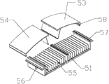
Fig. 5 is the structural representation of the embodiment of the present invention 2 radiators;
Wherein, 1 is control chamber upper cover, and 2 is control chamber lower cover, and 3 is front end chamber upper cover, 4 is front end chamber lower cover, and 5 is radiator, and 6 is joint pin, and 11 is the snap close of uncapping, 12 is spring, and 13 is screw, and 14 is nut, and 21 is horizontal tube standing groove, 22 is locking plate, and 51 is radiating fin, and 52 is monoblock type cambered surface, and 53 is the first cambered surface, 54 is the second cambered surface, and 55 is fixed light source face, and 56 is cable-through hole, 57 is draw-in groove, and 58 is fastener, and 59 is crossed beam trunking.
The specific embodiment
Below in conjunction with drawings and Examples, the present invention is further described.
As shown in FIG. 1 to 3, LED street lamp of the present invention, comprise the cavity with lamp body, cavity comprises front end chamber, heat radiation chamber and control chamber, front end chamber, heat radiation chamber and control chamber connect successively, heat radiation chamber front end is located in front end chamber, heat radiation is provided with radiator 5 in chamber, the front end of control chamber is located at again in heat radiation chamber, control chamber rear end is provided with the joint pin 6 being connected with lamp stand, also comprise the control chamber upper cover 1 and control chamber lower cover 2 that are arranged at respectively control chamber top and bottom, and the front end chamber upper cover 3 and the front end chamber lower cover 4 that are arranged at respectively top, front end chamber and bottom, in control chamber lower cover 2, be provided with horizontal tube standing groove 21.
Use the special-purpose horizontal tube being equipped with, be positioned over horizontal tube standing groove 21.Installation personnel relies on the characteristic range estimation of horizontal tube that light fixture is adjusted to after left and right horizontal, takes off horizontal tube and takes care of with installation personnel.The method can avoid road to occur the inconsistent problem of brightness.In addition, horizontal tube is not arranged on street lamp foremost, and is mounted in rear end, avoids the restriction in length, aerial ladder distance or the space of lamp body to bring inconvenience in the defect of watching level point; And therefore owing to can horizontal tube being taken off and take away, can avoid horizontal tube long-term work in the exposure air of low temperature, high temperature and intensive ultraviolet and explosion increases the service life after adjustment level, cost-saving.In addition, because meeting is opened control chamber upper cover 1 when adjusting or overhaul street lamp, control chamber lower cover 2 can not be unlocked, so the stability of control chamber lower cover 2 is strong, can keep preferably the stable and level of each parts and horizontal tube standing groove 21.
Because the control chamber of existing street lamp is not easy to open or close, need to operate by instrument, reduce the I&M efficiency of street lamp.Therefore in order to improve the I&M efficiency of street lamp, make control chamber be easy to open and closure, at control chamber upper cover 1, be provided with movable part, control chamber lower cover 2 is provided with fixture with the position that movable part matches, fixture and movable part are suitable, when movable part is subject to certain effect power, can be combined with fixture and enter tight lock status.Fixture and movable part can be separately positioned on the avris of control chamber lower cover 2 and control chamber upper cover 1, also can lay respectively at other positions on control chamber lower cover 2 and control chamber upper cover 1, as long as the position of the two matches, can effectively realize the stressed rear and fixture locking of movable part.Based on cost consideration, its movable part can adopt buckle, and fixture can adopt draw-in groove.Buckle is inserted in draw-in groove, can realize the closure of control chamber upper cover 1 and control chamber lower cover 2; Buckle is extracted to draw-in groove, can open control chamber upper cover 1.Yet the device lifetime of the method is limited, along with access times how after, be easy to rupture.In order to guarantee that use is stable and the life-span is longer, movable part can adopt the snap close 11 of uncapping being connected with control chamber upper cover 1 by spring 12, and fixture adopts locking plate 22.Use successively screw 13, spring 12 and nut 14 snap close 11 of uncapping to be fixed on control chamber upper cover 1, utilize screw that locking plate 22 is fixed on control chamber lower cover 2, the snap close 11 of uncapping is all cambered surface with the contact-making surface of locking plate 22; When control chamber upper cover 1 is covered downwards, the snap close 11 of uncapping touches with the contact-making surface of locking plate 22, the snap close 11 of uncapping is subject to the resistance of locking plate 22 automatically to after-contraction, when the cambered surface of the snap close 11 of uncapping is crossed locking plate 22, the snap close 11 of uncapping is automatically rebounded and enters tight lock status by spring 12, control chamber upper cover 1 and control chamber lower cover 2 closures; If open control chamber upper cover 1, only need will uncap snap close 11 to street lamp front end, the cavity direction that dispels the heat promotes.In Fig. 2, locking plate 22 is positioned at the avris position of control chamber lower cover 2, accordingly, the uncap snap close 11 corresponding with it is positioned at the same avris position of control chamber upper cover 1, and locking plate 22 matches with the position of the snap close 11 of uncapping, in order more directly to show relation and the structure of screw 13, spring 12, nut 14 and the snap close 11 of uncapping, therefore the consideration based on being convenient to view in Fig. 3, is plotted in above-mentioned each parts at the center of control chamber lower cover 2.
Embodiment 1
As shown in Figure 4, in this example, the radiator 5 of LED street lamp comprises radiator back and several radiating fins 51, and the number of radiating fin 51 is relevant to heat-sinking capability.Radiator back is monoblock type cambered surface 52, affects its heat-sinking capability and light fixture weight, and be easy to processing to prevent that a large amount of dust or other solids are deposited on radiating fin 51, reduces manufacture difficulty.Fixed light source face 55 is whole plane, is fixed with LED light source module on it, and radiating fin 51 is global design with fixed light source face 55, further to reduce difficulty of processing.Between radiating fin 51 and radiator back, be provided with louvre to strengthen heat-sinking capability, particularly, can be so that middle fin be connected with monoblock type cambered surface 52 at a radiating fin 51 going up along its length bosom, make it monoblock type cambered surface 52 play support fixation, its main purpose is the shape that keeps monoblock type cambered surface 52, make it not yielding, and all offer louvre between other radiating fins 51 and monoblock type cambered surface 52.In order further to strengthen heat-sinking capability, can expand louvre, for example, can, except middle fin, will between other radiating fins 51 and monoblock type cambered surface 52, be designed to engraved structure.In addition can, along crossed beam trunking 59 is set in width section direction, so that through LED light source module power line, connect up rationally in make to dispel the heat chamber and control chamber, avoid wire harness to be wound around and make troubles.
As shown in Figure 5, in this example, the radiator 5 of LED street lamp comprises radiator back and several radiating fins 51, radiating fin more than 51, and heat dispersion is better.Fixed light source face 55 is whole plane, is fixed with LED light source module on it, and radiating fin 51 is global design with fixed light source face 55, to reduce difficulty of processing.The middle fin of radiator 5 of take is symmetry axis at a radiating fin 51 going up along its length bosom, and radiator back comprises the first symmetrical cambered surface 53 and the second cambered surface 54, with cost-saving; In addition asymmetrical two cambered surfaces also can realize same function, and just cost is slightly high.Middle fin is i.e. fixing fin also, can play the support fixation to radiator back.Two of the left and right avris of radiator and fixedly the both sides of fin along radiator 5 widths, be provided with draw-in groove 57, the first cambered surfaces 53 and the second cambered surface 54 broad ways are provided with the fastener 58 suitable with draw-in groove 57.Fastener 58 is inserted to draw-in groove 57, can the first cambered surface 53 and the second cambered surface 54 are fixed and be supported, make it not yielding, between at least one radiating fin and radiator 5 backs, be provided with louvre.For example, can between other radiating fins 51 except fixing fin and the first cambered surface 53 and the second cambered surface 54, all offer louvre.In order further to strengthen heat-sinking capability, can expand louvre, for example, can, except middle fin, will between other radiating fins 51 and the first cambered surface 53 and the second cambered surface 54, be designed to engraved structure.So design, can reduce difficulty of processing, and prevents that a large amount of dust or other solids are deposited in and in radiator fins, affect its heat-sinking capability and light fixture weight.
In order to make in cavity wiring rationally, described radiator 5 also comprises and is arranged at radiator 5 along the cable-through hole 56 in length cross-wise direction, so that through LED light source module power line, in addition, cable-through hole 56 also can be arranged at radiator 5 along in width section direction.
Claims (9)
1.LED street lamp, comprise the cavity with lamp body, it is characterized in that, cavity comprises front end chamber, heat radiation chamber and control chamber, heat radiation chamber front end is located in front end chamber, heat radiation is provided with radiator (5) in chamber, the front end of control chamber is located at again in heat radiation chamber, control chamber rear end is provided with the joint pin (6) being connected with lamp stand, also comprise the control chamber upper cover (1) and control chamber lower cover (2) that are arranged at respectively control chamber top and bottom, and the front end chamber upper cover (3) and the front end chamber lower cover (4) that are arranged at respectively top, front end chamber and bottom, in control chamber lower cover (2), be provided with horizontal tube standing groove (21).
2. LED street lamp as claimed in claim 1, it is characterized in that, described radiator (5) comprises radiator back and at least one radiating fin (51), and radiator back is monoblock type cambered surface (52), between radiating fin (51) and radiator back, is provided with louvre.
3. LED street lamp as claimed in claim 2, is characterized in that, described radiator (5) also comprises crossed beam trunking, and described crossed beam trunking is arranged at radiator (5) along in width section direction.
4. LED street lamp as claimed in claim 1, it is characterized in that, described radiator (5) comprises radiator back and at least one radiating fin (51), radiator back comprises symmetrical the first cambered surface (53) and the second cambered surface (54), between radiating fin (51) and radiator back, is provided with louvre.
5. LED street lamp as claimed in claim 4, it is characterized in that, along the radiating fin (51) in the middle of radiator (5) length direction, it is fixing fin, two avris of radiator (5) and fixedly fin both sides are provided with draw-in groove (57) along radiator (5) width, and the first cambered surface (53) is provided with the fastener (58) suitable with draw-in groove (57) with the second cambered surface (54) along radiator (5) width.
6. LED street lamp as claimed in claim 5, is characterized in that, described radiator (5) also comprises cable-through hole (56), and cable-through hole (56) is arranged at radiator (5) along in length cross-wise direction.
7. LED street lamp as claimed in claim 1, it is characterized in that, described control chamber upper cover (1) is provided with movable part, control chamber lower cover (2) is provided with fixture with the position that movable part matches, fixture and movable part are suitable, when movable part is subject to certain effect power, can be combined with fixture and enter tight lock status.
8. LED street lamp as claimed in claim 7, is characterized in that, described movable part is buckle, and fixture is draw-in groove.
9. LED street lamp as claimed in claim 7, it is characterized in that, the uncap snap close (11) of described movable part for being connected with control chamber upper cover (1) by spring (12), fixture is locking plate (22), the snap close (11) of uncapping is all cambered surface with the contact-making surface of locking plate (22), when the snap close (11) of uncapping contacts with locking plate (22), the snap close (11) of uncapping is subject to locking plate (22) resistance automatically to after-contraction, when the cambered surface of the snap close of uncapping (11) is crossed locking plate (22), the snap close of uncapping (11) is automatically rebounded and enters tight lock status by spring (12).
Priority Applications (1)
| Application Number | Priority Date | Filing Date | Title |
|---|---|---|---|
| CN201410007105.XA CN103672755A (en) | 2014-01-07 | 2014-01-07 | LED (light emitting diode) streetlamp |
Applications Claiming Priority (1)
| Application Number | Priority Date | Filing Date | Title |
|---|---|---|---|
| CN201410007105.XA CN103672755A (en) | 2014-01-07 | 2014-01-07 | LED (light emitting diode) streetlamp |
Publications (1)
| Publication Number | Publication Date |
|---|---|
| CN103672755A true CN103672755A (en) | 2014-03-26 |
Family
ID=50311101
Family Applications (1)
| Application Number | Title | Priority Date | Filing Date |
|---|---|---|---|
| CN201410007105.XA Pending CN103672755A (en) | 2014-01-07 | 2014-01-07 | LED (light emitting diode) streetlamp |
Country Status (1)
| Country | Link |
|---|---|
| CN (1) | CN103672755A (en) |
Cited By (2)
| Publication number | Priority date | Publication date | Assignee | Title |
|---|---|---|---|---|
| CN106338039A (en) * | 2016-10-28 | 2017-01-18 | 东莞勤上光电股份有限公司 | Street lamp |
| CN106604475A (en) * | 2017-01-10 | 2017-04-26 | 济南爱默生电源有限公司 | LED streetlamp illumination light adjusting system based on DC remote power supply |
Citations (10)
| Publication number | Priority date | Publication date | Assignee | Title |
|---|---|---|---|---|
| CN201487726U (en) * | 2009-09-02 | 2010-05-26 | 童先平 | Led street lamp |
| CN201521865U (en) * | 2009-09-29 | 2010-07-07 | 上海澳星照明电器制造有限公司 | Street lamp convenient to be mounted |
| CN102734711A (en) * | 2012-07-04 | 2012-10-17 | 天宝电子(惠州)有限公司 | LED road lamp |
| CN202791765U (en) * | 2012-08-10 | 2013-03-13 | 童先平 | Novel light emitting diode (LED) road lamp |
| CN103174997A (en) * | 2012-03-15 | 2013-06-26 | 杭州华普永明光电股份有限公司 | Light-emitting diode (LED) illuminating device |
| CN203147513U (en) * | 2013-04-02 | 2013-08-21 | 宁海县先平文具压铸有限公司 | Panel street lamp |
| CN203147512U (en) * | 2013-04-02 | 2013-08-21 | 宁海县先平文具压铸有限公司 | Novel illuminating street lamp |
| CN203147511U (en) * | 2013-04-02 | 2013-08-21 | 宁海县先平文具压铸有限公司 | Integrated road lamp |
| CN203190254U (en) * | 2013-04-02 | 2013-09-11 | 宁海县先平文具压铸有限公司 | Mesh-type radiating street lamp |
| CN203718523U (en) * | 2014-01-07 | 2014-07-16 | 雅安移路照明科技有限公司 | Led street lamp |
-
2014
- 2014-01-07 CN CN201410007105.XA patent/CN103672755A/en active Pending
Patent Citations (10)
| Publication number | Priority date | Publication date | Assignee | Title |
|---|---|---|---|---|
| CN201487726U (en) * | 2009-09-02 | 2010-05-26 | 童先平 | Led street lamp |
| CN201521865U (en) * | 2009-09-29 | 2010-07-07 | 上海澳星照明电器制造有限公司 | Street lamp convenient to be mounted |
| CN103174997A (en) * | 2012-03-15 | 2013-06-26 | 杭州华普永明光电股份有限公司 | Light-emitting diode (LED) illuminating device |
| CN102734711A (en) * | 2012-07-04 | 2012-10-17 | 天宝电子(惠州)有限公司 | LED road lamp |
| CN202791765U (en) * | 2012-08-10 | 2013-03-13 | 童先平 | Novel light emitting diode (LED) road lamp |
| CN203147513U (en) * | 2013-04-02 | 2013-08-21 | 宁海县先平文具压铸有限公司 | Panel street lamp |
| CN203147512U (en) * | 2013-04-02 | 2013-08-21 | 宁海县先平文具压铸有限公司 | Novel illuminating street lamp |
| CN203147511U (en) * | 2013-04-02 | 2013-08-21 | 宁海县先平文具压铸有限公司 | Integrated road lamp |
| CN203190254U (en) * | 2013-04-02 | 2013-09-11 | 宁海县先平文具压铸有限公司 | Mesh-type radiating street lamp |
| CN203718523U (en) * | 2014-01-07 | 2014-07-16 | 雅安移路照明科技有限公司 | Led street lamp |
Cited By (3)
| Publication number | Priority date | Publication date | Assignee | Title |
|---|---|---|---|---|
| CN106338039A (en) * | 2016-10-28 | 2017-01-18 | 东莞勤上光电股份有限公司 | Street lamp |
| CN106604475A (en) * | 2017-01-10 | 2017-04-26 | 济南爱默生电源有限公司 | LED streetlamp illumination light adjusting system based on DC remote power supply |
| CN106604475B (en) * | 2017-01-10 | 2018-01-19 | 济南爱默生电源有限公司 | LED street lamp illumination light adjusting system based on direct-current remote feeding power |
Similar Documents
| Publication | Publication Date | Title |
|---|---|---|
| KR101176442B1 (en) | led illumination lamp | |
| CN102216674A (en) | Light emitting diode (led) roadway lighting fixture | |
| CN104089206B (en) | A kind of LED lamp cell cube and combination type LED lamp | |
| CN105066031A (en) | Modular LED (Light Emitting Diode) street lamp and heat sink thereof | |
| CN204785929U (en) | High -power module street lamp | |
| CN201636628U (en) | Bar type LED projection lamp | |
| CN204026327U (en) | A kind of Modular LED street lamp | |
| CN103672755A (en) | LED (light emitting diode) streetlamp | |
| CN203718523U (en) | Led street lamp | |
| CN202521449U (en) | Integrated light emitting diode (LED) explosion-proof lamp | |
| WO2011022945A1 (en) | Led modular light-source and high-power led lamp combined by the same | |
| KR101125807B1 (en) | Head for LED street light | |
| CN102385219B (en) | Intelligent traffic LED flash lamp and circuit thereof | |
| CN201652045U (en) | Mining explosion-proof type LED flood light | |
| CN203384768U (en) | LED street lamp with adjustable lighting angle | |
| CN202176949U (en) | Split type light-emitting diode (LED) anti-explosion lamp | |
| CN204785983U (en) | Led street lamp | |
| CN204066641U (en) | A kind of novel court display screen box body | |
| CN203927661U (en) | Marine LED bulkhead lamp capable | |
| CN202349739U (en) | Mine explosion-proof LED (light emitting diode) strip-type roadway lamp | |
| CN102767716B (en) | Modular lamp integrating wiring channel and installation parts | |
| CN202812891U (en) | High-power paster light emitting diode (LED) grille lamp | |
| CN205938834U (en) | LED street lamp based on module splicing technology | |
| CN204026369U (en) | A kind of LED aisle lamp | |
| CN204403850U (en) | A kind of LED light module |
Legal Events
| Date | Code | Title | Description |
|---|---|---|---|
| PB01 | Publication | ||
| PB01 | Publication | ||
| C10 | Entry into substantive examination | ||
| SE01 | Entry into force of request for substantive examination | ||
| RJ01 | Rejection of invention patent application after publication |
Application publication date: 20140326 |
|
| RJ01 | Rejection of invention patent application after publication |