CN1036664A - Chromoscope with modified model shadow mask-frame assembly - Google Patents
Chromoscope with modified model shadow mask-frame assembly Download PDFInfo
- Publication number
- CN1036664A CN1036664A CN89100308A CN89100308A CN1036664A CN 1036664 A CN1036664 A CN 1036664A CN 89100308 A CN89100308 A CN 89100308A CN 89100308 A CN89100308 A CN 89100308A CN 1036664 A CN1036664 A CN 1036664A
- Authority
- CN
- China
- Prior art keywords
- flange
- shadow mask
- framework
- panel
- chromoscope
- Prior art date
- Legal status (The legal status is an assumption and is not a legal conclusion. Google has not performed a legal analysis and makes no representation as to the accuracy of the status listed.)
- Expired - Lifetime
Links
Images


Classifications
-
- H—ELECTRICITY
- H01—ELECTRIC ELEMENTS
- H01J—ELECTRIC DISCHARGE TUBES OR DISCHARGE LAMPS
- H01J29/00—Details of cathode-ray tubes or of electron-beam tubes of the types covered by group H01J31/00
- H01J29/02—Electrodes; Screens; Mounting, supporting, spacing or insulating thereof
- H01J29/06—Screens for shielding; Masks interposed in the electron stream
- H01J29/07—Shadow masks for colour television tubes
- H01J29/073—Mounting arrangements associated with shadow masks
-
- H—ELECTRICITY
- H02—GENERATION; CONVERSION OR DISTRIBUTION OF ELECTRIC POWER
- H02K—DYNAMO-ELECTRIC MACHINES
- H02K5/00—Casings; Enclosures; Supports
- H02K5/04—Casings or enclosures characterised by the shape, form or construction thereof
- H02K5/16—Means for supporting bearings, e.g. insulating supports or means for fitting bearings in the bearing-shields
-
- H—ELECTRICITY
- H01—ELECTRIC ELEMENTS
- H01J—ELECTRIC DISCHARGE TUBES OR DISCHARGE LAMPS
- H01J2229/00—Details of cathode ray tubes or electron beam tubes
- H01J2229/07—Shadow masks
- H01J2229/0722—Frame
Abstract
A kind of rectangular color picture tube of shadow mask type (8) comprises shadow mask-frame assembly (30) and the supporting arrangement (34) thereof that has improved.Framework (32,32 ') has two basic vertical flanges, first flange (36,36 ') and second flange (38,38 ').First flange stretches out along the screen of pipe (22) dorsad from second flange.Second flange stretches out towards the direction of shadow mask (24) from first flange edge.Second flange comprises from the edge periphery fin (40,40 ') separated by a distance that it stretches out.Shadow mask is embedded into framework and is fixed on the fin.In a most preferred embodiment, all angles of framework are clipped.Spring (46) is linked on the corner that framework respectively clips, so that shadow mask frame level part is bearing in the pipe.
Description
The present invention relates to a kind of like this chromoscope, its shadow mask is attached on the outer rim framework that suspends with respect to cathode luminescence screen, the invention particularly relates to the shadow mask-frame assembly of a kind of novelty of this class pipe.
In chromoscope, depend on the alignment precision of shadow mask hole and described optical screen elemental area during the pipe work to a great extent from the precision of each elemental area of electron gun electrons emitted bundle starter cathode electron excitation optical screen.At the initial duration of work of picture tube, shadow mask is because of being subjected to beam bombardment heating and its speed faster compared with heavier outer rim framework.Because it is less to reach the heat of shadow mask outer rim, makes the expansion rate of shadow mask part with holes bigger than its outer rim expansion rate.The shadow mask outer rim makes the aperture part become the hemisphere protuberance as a cold belt of wound hole path portion, this arching makes by the electron beam of shadow mask and can not aim at exactly with their corresponding light screen image vegetarian noodles is long-pending, thereby produces undesirable color shift (shift in color) on optical screen.
In most popular chromoscope type, described outer rim framework by a plurality of spring suspensions on a panel panel, these springs or be soldered directly to described framework, or be welded on the some plates that itself are soldered to described framework again.In direct welding scheme, described spring is made by bimetallic metal material, and in the plate scheme, described plate is made with bimetallic material.When heat when shadow mask makes spring or plate heating by the framework transmission, described bimetallic material is done different the expansion, thus flexural spring or plate and cause that shadow mask-frame assembly shifts to the display screen of picture tube.
Usually, in the rectangle panel panel scope of pipe, use 3 or 4 springs to remove to support a shadow mask-frame assembly.In the bracing or strutting arrangement of three springs, a common spring is positioned at the top mid point of shadow mask, and in addition two springs then are arranged on the pipe side between two angles of center, shadow mask side and shadow mask bottom.In the bracing or strutting arrangement of four springs, these springs place the top of shadow mask and the left side and the center, the right of bottom centre and shadow mask usually.As mentioned above, in the bracing or strutting arrangement of three and four springs, slight distortion and the skew with respect to panel may take place in shadow mask-frame assembly during pipe work.
Therefore, be necessary to develop and this arching of shadow mask can be reversed the picture tube that reduces to the supporting arrangement of minimum shadow mask-frame assembly with offset problem a kind of having, and its manufacturing expense is saved.The present invention has just satisfied this needs fully.
Comprise an improved shadow mask-frame assembly by mask color picture of the present invention.This framework has two basic vertical flanges, i.e. first flange and second flange.First flange deviates from the tube fluorescent screen direction from second flange and stretches out.Second flange then stretches out towards the shadow mask direction from first flange.Second flange includes the fin that separates along outer rim that stretches out from it there.Shadow mask promptly is fixed on these fins.In a most preferred embodiment, all angles of described framework are all clipped, and with each of spring and framework by the interconnection of corner of being clipped, with at the described shadow mask-frame assembly of picture tube internal support.
In the accompanying drawing:
Fig. 1 (the 1st) is an end view that intercepts vertically that embodies chromoscope of the present invention.
Fig. 2 (the 2nd) is the panel panel of pipe shown in Figure 1 and the axial local top view that intercepts of shadow mask-frame assembly.
Fig. 3 (the 3rd) is the panel panel that intercepted along Fig. 2 line 3-3 and the partial bottom view of shadow mask-frame assembly.
Fig. 4 (the 2nd) is one jiao a cross section view of Fig. 1 kinescope screen faceplate panels and framework, also shows a bearing assembly simultaneously.
Fig. 5 (the 2nd) is a front view of Fig. 4 bearing assembly.
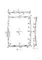
Fig. 6 (the 4th) is the front view of Fig. 1 picture tube framework.
Fig. 7 (the 4th) is the framework cross section view that the line 7-7 along Fig. 6 is intercepted.
Fig. 8 (the 4th) is the framework cross section view that the line 8-8 along Fig. 6 is intercepted.
Fig. 9 (the 3rd) is the framework drawing in side sectional elevation that the 9-9 line along Fig. 6 is intercepted.
Figure 10 (the 3rd) is the framework drawing in side sectional elevation that the 10-10 line along Fig. 6 is intercepted.
Figure 11 (the 3rd) is another the alternative framework drawing in side sectional elevation corresponding to Fig. 9 view.
Figure 12 (the 3rd) is another the alternative framework drawing in side sectional elevation corresponding to Figure 10 view.
Fig. 1 represents a rectangle chromoscope 8 with glass shell 10, and it comprises a rectangle panel panel 12 and a neck 14 that is connected by rectangular funnel body 16.Panel panel 12 comprises a visual panel 18 and is sealed to the outer rim flange or the sidewall 20 of infundibular body 16.Panel panel 12 comprises two orthogonal axles: the major axis X-X of parallel its broad size (being generally horizontal direction), peaceful Xingqi is than the countershaft Y-Y of narrow dimension (being generally vertical direction).Described major and minor axle is perpendicular to the center longitudinal axis Z-Z of picture tube, and this longitudinal axis is by the center of neck 14 and the center of panel 12.Inner surface by panel 18 is equipped with a tricolour phosphor screen of inlaying 22.This phosphor screen is preferably the row screen that has the photoluminescence line that is roughly parallel to countershaft Y-Y extension.This phosphor screen also is chosen as a screen on the other hand.A porous selecting electrode for colour is a shadow mask 24, by novel apparatus, is movably mounted with the predetermined space with respect to screen 22.An electron gun 26 centrally is installed in the neck 14, to produce three-beam electron-beam and to guide its convergence path that passes through shadow mask 24 to arrive phosphor screen 22.
The picture tube of Fig. 1 is designed to and an external magnetic deflection system adapted, for example adjoins the deflecting coil 28 of cone to the neck node.When coil 28 excited target, it places under the action of a magnetic field described three electron-beam, makes level and vertical scanning thereby make in the rectangular raster of these electron beams on phosphor screen 22.
Shadow mask-frame assembly supporting arrangement 34 comprises a support unit on each angle of four jiaos of framework and panels.Each support unit comprises 44, one springs 46 of a pin and bimetallic plates 48.Each pin 44 is hollow cone shape hardwares and is embedded in the sidewall 20.Every bimetallic plates 48 are soldered to flange 36 in corner 42 places that the quilt of framework 32 cut so that it extends towards panel 18, in the face of the side coefficient of expansion of pin less.After each spring 46 was welded to bimetallic plates 48, the one end was bent to about 22 ° backward.Hole 50 engages with the tapered tip of pin 44 near the free end of each spring 46.
As Fig. 1, shown in 2 and 3, shadow mask 24 comprises the part with holes 25 of a bending; The atresia marginal portion 27 of belt passing round bore portion 25; With from the marginal portion 27 to palintrope and deviate from the skirt body portion 29 that phosphor screen 22 extends.Shadow mask 24 is embedded into and promptly places framework 32 inner and only in fin 40 place's contact frame 32.The skirt body portion 29 of shadow mask is soldered directly to 8 in 12 fins 40.These 8 fins are positioned described four angles and major and minor axle place.Four fins are as vibration isolator in addition.For the supporting and the used fin number of vibration damping can change to some extent in other embodiments.
Though, framework 32 has been shown as has the some fins that separate 40 that stretch out from the remote edge of second flange 38, but shown in Figure 11 and 12, integrant fin 40 ' also can be from second flange 38 ' the part of the 3rd flange 52 that stretches out of remote edge.In the modification of this embodiment, framework 32 ' have U-shaped cross-section around its outer rim.Figure 11 represent corresponding to the framework 32 of Fig. 9 cross section same area ' cross section.Figure 12 represent for the framework 32 of Figure 10 cross section same area ' cross section.Framework 32 ' comprise first flange 36 ', this flange link second flange 38 ' connected mode the same with the mode of in the framework 32 first flange 36 being linked second flange 38.Except that flange 38 ' formation fin 40 ' those parts, the 3rd flange 52 with one less than 90 ° angle from second flange 38 ' stretch out.Fin 40 ' be forms with the projection in the 3rd flange 52, thus they can be vertically from second flange 38 ' stretch out.
Have shadow mask different earlier with most of, shadow mask 24 has very narrow marginal portion 27.The overscanning of only about 3% electron beam (overscan) provides enough electron beam energys for part 27, thereby makes its heating.Reducing marginal dimension provides assurance for reducing around with holes 25 cold belt of shadow mask 24 with the acting in conjunction that restriction contacts with framework 32, thereby has reduced the deflection of shadow mask.Simultaneously, skirt body portion 29 is made skirt body portion 29 deflection to some extent during the shadow mask heating with the restriction that fin 40 contacts, thereby further reduced the deflection of shadow mask.In addition, the bearing assembly at four jiaos of places of described framework and panel has been avoided the distortion and the skew of picture tube duration of work shadow mask frame.Also have, the shadow mask 24 in the shadow mask-frame assembly 30 be embedded into or be contained in framework 32 or 32 ' inside make the manufacturing of this assembly very fast and more accurate, thereby the better economic benefit of configuration aspects is provided.For example, because the longitudinal axis Z-Z of the parallel picture tube of fin, so shadow mask can be inserted in the framework from the framework either side.This just makes following installation order become possibility: promptly earlier framework is installed in the panel panel, and then from its rear side shadow mask is inserted or embeds in the framework.In case correctly in place, shadow mask can be welded on the fin that is easy to reach.
Claims (5)
1, chromoscope, it comprises that one has the shell of a rectangle panel panel and coupled neck, described pipe also comprises the rectangle shadow mask that is fixed to an outer rim framework of being installed by the supporting arrangement in the described panel, cathode luminescence screen on inner surface that is positioned at described faceplate panel, with an electron gun that is positioned at described neck, be used to form if in electron beam and guide described electron beam to get on the described screen by described shadow mask; It is characterized in that described framework (32,32 ') flange of two L-shaped shape of cross sections of approximate vertical arranged, first flange (36 in the described flange, 36 ') deviate from described panel (18) and stretch out, and second flange (38,38 ') in the described flange stretches out towards described shadow mask (24), and described second flange comprises from its phase of stretching out fin (40 across a certain distance, 40 '), and described shadow mask is fixed to described fin.
2,, it is characterized in that described supporting arrangement (34) comprises the assembly on four jiaos that are in described panel panel (12) according to the chromoscope of claim 1.
3, according to the chromoscope of claim 1, four jiaos that it is characterized in that described framework (32,32 ') by amputation.
4,, it is characterized in that described supporting arrangement (34) comprises that four quilts that are fixed to described framework (32,32 ') cut on each of corner according to the chromoscope of claim 3.
5, according to the chromoscope of claim 1, it is characterized in that: described fin (40 ') is in aggregates with the 3rd flange (52) that stretches out from described second flange (38 ').
Applications Claiming Priority (2)
| Application Number | Priority Date | Filing Date | Title |
|---|---|---|---|
| US17589588A | 1988-03-30 | 1988-03-30 | |
| US175895 | 1988-03-30 |
Publications (2)
| Publication Number | Publication Date |
|---|---|
| CN1036664A true CN1036664A (en) | 1989-10-25 |
| CN1015766B CN1015766B (en) | 1992-03-04 |
Family
ID=22642109
Family Applications (1)
| Application Number | Title | Priority Date | Filing Date |
|---|---|---|---|
| CN89100308A Expired CN1015766B (en) | 1988-03-30 | 1989-01-16 | Colour picture tube having improved shadow mask-frame assembly |
Country Status (6)
| Country | Link |
|---|---|
| EP (1) | EP0335606B1 (en) |
| JP (1) | JPH07120511B2 (en) |
| KR (1) | KR0130973B1 (en) |
| CN (1) | CN1015766B (en) |
| CA (1) | CA1292500C (en) |
| DE (1) | DE68918737T2 (en) |
Families Citing this family (1)
| Publication number | Priority date | Publication date | Assignee | Title |
|---|---|---|---|---|
| CN1056170C (en) * | 1994-06-09 | 2000-09-06 | 太原工业大学 | Continuous coking process and equipment thereof |
Family Cites Families (6)
| Publication number | Priority date | Publication date | Assignee | Title |
|---|---|---|---|---|
| US2905846A (en) * | 1956-03-29 | 1959-09-22 | Owens Illinois Glass Co | Electrode support for cathode-ray tubes |
| US2922063A (en) * | 1956-11-07 | 1960-01-19 | Sylvania Electric Prod | Target assembly for cathode ray tubes |
| US4056755A (en) * | 1975-12-22 | 1977-11-01 | Rca Corporation | Color picture tube having mask-frame assembly with reduced thickness |
| NL8102182A (en) * | 1981-05-04 | 1982-12-01 | Philips Nv | COLOR IMAGE TUBE. |
| JPS59160942A (en) * | 1983-03-04 | 1984-09-11 | Toshiba Corp | Manufacture of color picture tube |
| US4599533A (en) * | 1984-05-15 | 1986-07-08 | Rca Corporation | Color picture tube having shadow mask frame with truncated corners |
-
1988
- 1988-12-15 CA CA000586018A patent/CA1292500C/en not_active Expired - Fee Related
-
1989
- 1989-01-16 CN CN89100308A patent/CN1015766B/en not_active Expired
- 1989-03-23 EP EP89302930A patent/EP0335606B1/en not_active Expired - Lifetime
- 1989-03-23 DE DE68918737T patent/DE68918737T2/en not_active Expired - Lifetime
- 1989-03-29 JP JP1080218A patent/JPH07120511B2/en not_active Expired - Lifetime
- 1989-03-29 KR KR1019890003949A patent/KR0130973B1/en not_active IP Right Cessation
Also Published As
| Publication number | Publication date |
|---|---|
| KR890015330A (en) | 1989-10-30 |
| JPH07120511B2 (en) | 1995-12-20 |
| KR0130973B1 (en) | 1998-04-15 |
| CA1292500C (en) | 1991-11-26 |
| CN1015766B (en) | 1992-03-04 |
| EP0335606A2 (en) | 1989-10-04 |
| EP0335606B1 (en) | 1994-10-12 |
| DE68918737D1 (en) | 1994-11-17 |
| EP0335606A3 (en) | 1990-01-17 |
| JPH01286235A (en) | 1989-11-17 |
| DE68918737T2 (en) | 1995-05-11 |
Similar Documents
| Publication | Publication Date | Title |
|---|---|---|
| US6002203A (en) | Cathode ray tube having an envelope shaped to reduce beam deflection power requirements | |
| CA1206513A (en) | Cathode-ray tube | |
| KR100310404B1 (en) | Shadow mask for color cathode ray tube and its manufacturing method | |
| US6268690B1 (en) | Color cathode ray tube with face panel and shadow mask having curved surfaces that meet specified relationships | |
| KR940000301B1 (en) | Color picture tube having improved shadow mask-frame assembly support | |
| US4736133A (en) | Inline electron gun for high resolution display tube having improved screen grid plate portion | |
| CN1036664A (en) | Chromoscope with modified model shadow mask-frame assembly | |
| CN1267955C (en) | Compliant tension mask assembly | |
| JP2001236898A (en) | Internal magnetic shield and cathode-ray tube | |
| CN1251281C (en) | Color picture tube having a low expansion tension mask attached to a higher expansion frame | |
| JP3420778B2 (en) | Color display tube | |
| US5689150A (en) | Color picture tube having improved shadow mask frame | |
| JP3222640B2 (en) | Color picture tube equipment | |
| JP3082601B2 (en) | Shadow mask type color cathode ray tube | |
| CA1128981A (en) | Color picture tube having improved corrugated apertured mask and method of making same | |
| JP3178943B2 (en) | Picture tube device | |
| KR100466681B1 (en) | Colorpicture tube having improved shadow mask-frame assembly support | |
| CN1277454A (en) | Color-selecting parts, method for preventing colour-selecting parts vibrating | |
| JP2553347B2 (en) | Cathode ray tube | |
| KR950012699B1 (en) | Crt with s/m | |
| KR100438507B1 (en) | Shadow mask and color cathode ray tube | |
| KR100596231B1 (en) | A Spring of Color CRT | |
| KR20010014826A (en) | Cathode-ray tube with internal magnetic shield | |
| KR20010112850A (en) | Cathode-ray tube | |
| JPH05128978A (en) | Color cathode-ray tube |
Legal Events
| Date | Code | Title | Description |
|---|---|---|---|
| C06 | Publication | ||
| PB01 | Publication | ||
| C10 | Entry into substantive examination | ||
| SE01 | Entry into force of request for substantive examination | ||
| C13 | Decision | ||
| GR02 | Examined patent application | ||
| C14 | Grant of patent or utility model | ||
| GR01 | Patent grant | ||
| C15 | Extension of patent right duration from 15 to 20 years for appl. with date before 31.12.1992 and still valid on 11.12.2001 (patent law change 1993) | ||
| OR01 | Other related matters | ||
| C17 | Cessation of patent right | ||
| CX01 | Expiry of patent term |