CN103658813A - Rack type oil level sensor die-cutting cutter - Google Patents
Rack type oil level sensor die-cutting cutter Download PDFInfo
- Publication number
- CN103658813A CN103658813A CN201310609138.7A CN201310609138A CN103658813A CN 103658813 A CN103658813 A CN 103658813A CN 201310609138 A CN201310609138 A CN 201310609138A CN 103658813 A CN103658813 A CN 103658813A
- Authority
- CN
- China
- Prior art keywords
- cutter
- level sensor
- rack
- hinged
- oil level
- Prior art date
- Legal status (The legal status is an assumption and is not a legal conclusion. Google has not performed a legal analysis and makes no representation as to the accuracy of the status listed.)
- Pending
Links
Images
Abstract
A rack type oil level sensor die-cutting cutter comprises a support, a cutter rest and a cutter body, wherein the front end of the cutter rest is hinged to the front end of the support, a hinge seat is fixed at the lower portion of the rear end of the cutter rest, the hinge seat is hinged to an oblique bracing rod, and the rail end of the oblique bracing rod is hinged to one positioning block. A rack is arranged at the rear portion of the support, a tooth profile of the rack is rectangular, and the lower portion of the positioning block is provided with a tooth profile matched with the rack so that the positioning block can be installed on the rack. The front end of the cutter body is hinged to the front end of the cutter rest, the cutting edge is installed on the inner side of the cutter body in an embedded mode, and a cutter groove is formed in the cutter rest. The rack type oil level sensor die-cutting cutter enables oil level sensor products subjected to die cutting to be conveniently collected through the oblique cutter, waste does not easily accumulate and is easy to clear, and the die-cutting efficiency is improved. An inclination angle of the cutter rest is adjusted through movement of the oblique bracing rod, so that an operator can conveniently find an appropriate working inclination angle and can adjust the inclination angle of the cutter rest according to different models and sizes of the oil level sensor products.
Description
Technical field
The present invention relates to rack-and-pinion fuel level sensor die-cutting rule, belong to fuel level sensor secondary process apparatus field.
Background technology
Existing fuel level sensor, particularly adopts the fuel level sensor of column structure, needs manually to cut off part unnecessary on blank after machine-shaping, then encapsulates.
Prior art mostly adopts manual shearing, use be common scissors, cutting knife instrument, make the cutting efficiency of fuel level sensor lower.
Common cutting knife instrument, is placed on horizontal plane, and the fuel level sensor after cut-out is not easy to collect, and the blank after cut-out also easily produces and piles up.
Summary of the invention
The object of this invention is to provide a kind of rack-and-pinion fuel level sensor die-cutting rule, while having solved artificial blank efficiency low, be not easy to collect finished product and waste material easily produces the problem of accumulation, make the angle of inclination of die-cutting rule adjustable, convenient operation person adjusts to comfortable angle and operates simultaneously.
The object of the invention is to be achieved through the following technical solutions:
Rack-and-pinion fuel level sensor die-cutting rule, comprise support, tool rest, cutter hub, the front end of described tool rest and the front end of described support are hinged, the rear end lower of described tool rest is fixed with free bearing, described free bearing and a hound are hinged, and the end of described hound and a locating piece are hinged, rear portion at described support is provided with tooth bar, the profile of tooth of tooth bar is rectangle, the bottom of described locating piece is provided with the profile of tooth that matches with tooth bar and install, described locating piece is arranged on tooth bar, the front end of described cutter hub and the front end of described tool rest are hinged, and the embedded blade that is provided with of inner side edge at described cutter hub, cutter groove is installed on described tool rest.
By the rack-and-pinion fuel level sensor die-cutting rule of above-mentioned design, by the cutter tilting, make the fuel level sensor product after cross cutting be convenient to collect, and waste material is not easy to produce and pile up, be easy to cleaning, the efficiency of cross cutting is improved; And by the movement of hound, regulate the angle of inclination of tool rest, can make operator be convenient to find suitable work inclination angle, and operator can regulate according to the difference of the product type of fuel level sensor, size the inclination angle of tool rest.
Accompanying drawing explanation
According to drawings and embodiments the present invention is described in further detail below.
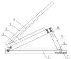
Fig. 1 is the structure chart of the rack-and-pinion fuel level sensor die-cutting rule described in the embodiment of the present invention.
The specific embodiment
As shown in Figure 1, rack-and-pinion fuel level sensor die-cutting rule of the present invention, comprise support 1, tool rest 2, cutter hub 3, the front end of the front end of described tool rest 2 and described support 1 is hinged, the rear end lower of described tool rest 2 is fixed with free bearing 4, described free bearing 4 and a hound 5 are hinged, and the end of described hound 5 and a locating piece 6 are hinged, at the rear portion of described support 1, be provided with tooth bar 7, the profile of tooth of tooth bar 7 is rectangle, the bottom of described locating piece 6 is provided with the profile of tooth that matches with tooth bar 7 and install, described locating piece 6 is arranged on tooth bar 7, the front end of the front end of described cutter hub 3 and described tool rest 2 is hinged, and the embedded blade 8 that is provided with of inner side edge at described cutter hub 3, on described tool rest 2, cutter groove 9 is installed.
By the rack-and-pinion fuel level sensor die-cutting rule of above-mentioned design, by the cutter tilting, make the fuel level sensor product after cross cutting be convenient to collect, and waste material is not easy to produce and pile up, be easy to cleaning, the efficiency of cross cutting is improved; And by the movement of hound, regulate the angle of inclination of tool rest, can make operator be convenient to find suitable work inclination angle, and operator can regulate according to the difference of the product type of fuel level sensor, size the inclination angle of tool rest.
Claims (1)
1. rack-and-pinion fuel level sensor die-cutting rule, comprise support, tool rest, cutter hub, it is characterized in that, the front end of described tool rest and the front end of described support are hinged, the rear end lower of described tool rest is fixed with free bearing, described free bearing and a hound are hinged, and the end of described hound and a locating piece are hinged, rear portion at described support is provided with tooth bar, the profile of tooth of tooth bar is rectangle, the bottom of described locating piece is provided with the profile of tooth that matches with tooth bar and install, described locating piece is arranged on tooth bar, the front end of described cutter hub and the front end of described tool rest are hinged, and the embedded blade that is provided with of inner side edge at described cutter hub, cutter groove is installed on described tool rest.
Priority Applications (1)
| Application Number | Priority Date | Filing Date | Title |
|---|---|---|---|
| CN201310609138.7A CN103658813A (en) | 2013-11-27 | 2013-11-27 | Rack type oil level sensor die-cutting cutter |
Applications Claiming Priority (1)
| Application Number | Priority Date | Filing Date | Title |
|---|---|---|---|
| CN201310609138.7A CN103658813A (en) | 2013-11-27 | 2013-11-27 | Rack type oil level sensor die-cutting cutter |
Publications (1)
| Publication Number | Publication Date |
|---|---|
| CN103658813A true CN103658813A (en) | 2014-03-26 |
Family
ID=50298267
Family Applications (1)
| Application Number | Title | Priority Date | Filing Date |
|---|---|---|---|
| CN201310609138.7A Pending CN103658813A (en) | 2013-11-27 | 2013-11-27 | Rack type oil level sensor die-cutting cutter |
Country Status (1)
| Country | Link |
|---|---|
| CN (1) | CN103658813A (en) |
Citations (6)
| Publication number | Priority date | Publication date | Assignee | Title |
|---|---|---|---|---|
| US4567802A (en) * | 1984-10-22 | 1986-02-04 | Witherspoon John K | Mortise and bevel cutter |
| CN2357367Y (en) * | 1998-06-22 | 2000-01-05 | 林晖 | Foldable double screen notebook computer |
| JP3702282B2 (en) * | 2003-06-27 | 2005-10-05 | クボタ松下電工外装株式会社 | Roofing cutting machine |
| CN101234574A (en) * | 2008-02-28 | 2008-08-06 | 马广忠 | Multifunctional teaching sector ruler and compass |
| CN201376301Y (en) * | 2008-12-26 | 2010-01-06 | 浙江吉利汽车有限公司 | Cutting device for polyurethane |
| CN203541690U (en) * | 2013-11-27 | 2014-04-16 | 无锡蚂蚁微威科技有限公司 | Rack type oil level sensor die cutter |
-
2013
- 2013-11-27 CN CN201310609138.7A patent/CN103658813A/en active Pending
Patent Citations (6)
| Publication number | Priority date | Publication date | Assignee | Title |
|---|---|---|---|---|
| US4567802A (en) * | 1984-10-22 | 1986-02-04 | Witherspoon John K | Mortise and bevel cutter |
| CN2357367Y (en) * | 1998-06-22 | 2000-01-05 | 林晖 | Foldable double screen notebook computer |
| JP3702282B2 (en) * | 2003-06-27 | 2005-10-05 | クボタ松下電工外装株式会社 | Roofing cutting machine |
| CN101234574A (en) * | 2008-02-28 | 2008-08-06 | 马广忠 | Multifunctional teaching sector ruler and compass |
| CN201376301Y (en) * | 2008-12-26 | 2010-01-06 | 浙江吉利汽车有限公司 | Cutting device for polyurethane |
| CN203541690U (en) * | 2013-11-27 | 2014-04-16 | 无锡蚂蚁微威科技有限公司 | Rack type oil level sensor die cutter |
Similar Documents
| Publication | Publication Date | Title |
|---|---|---|
| CN103658815A (en) | Die cutting rule with adjustable sliding chute | |
| CN203541690U (en) | Rack type oil level sensor die cutter | |
| CN203956981U (en) | A kind of paper cutter | |
| CN203565962U (en) | Sliding block adjusting type mould-cutting tool | |
| CN203541689U (en) | Inclined supporting rod type die-cutting knife for oil level sensors | |
| CN103658813A (en) | Rack type oil level sensor die-cutting cutter | |
| CN203541683U (en) | Sliding groove adjustable type die cutting knife | |
| CN103658820A (en) | Die cutting rule with adjustable sliding block | |
| CN203565968U (en) | Chain hole adjusting die cutter | |
| CN203565961U (en) | Die hole adjusting die cutter | |
| CN203565967U (en) | Multi-hinged support type die-cutting rule | |
| CN205200667U (en) | Reel iron sheet cutting device | |
| CN202180490U (en) | Horizontal punching device for solar battery adhesive-film cutting equipment | |
| CN201833060U (en) | Trimming mechanism | |
| CN203541687U (en) | Die cutter for supporting base sliding supporting type oil level sensor | |
| CN203541692U (en) | Die cutter for supporting base rolling supporting type oil level sensor | |
| CN203541685U (en) | Multiple-cutting-edge oil level sensor die cutter | |
| CN203565965U (en) | Locking screw bolt type mold cutter | |
| CN203541691U (en) | Binding strap type oil level sensor die cutter | |
| CN103658822A (en) | Locking-bolt type die cutting tool | |
| CN201997789U (en) | Online hydraulic section cutter | |
| CN103658828A (en) | Slanting pole supporting type die-cutting knife for oil-level sensor | |
| CN103658818A (en) | Die hole adjustment type die-cutting rule | |
| CN201579476U (en) | Plate shearing machine | |
| CN103658814A (en) | Die-cutting rule with multiple hinged supports |
Legal Events
| Date | Code | Title | Description |
|---|---|---|---|
| PB01 | Publication | ||
| PB01 | Publication | ||
| C10 | Entry into substantive examination | ||
| SE01 | Entry into force of request for substantive examination | ||
| C12 | Rejection of a patent application after its publication | ||
| RJ01 | Rejection of invention patent application after publication |
Application publication date: 20140326 |