CN103636266A - Communication device, communication control method - Google Patents
Communication device, communication control method Download PDFInfo
- Publication number
- CN103636266A CN103636266A CN201280033172.8A CN201280033172A CN103636266A CN 103636266 A CN103636266 A CN 103636266A CN 201280033172 A CN201280033172 A CN 201280033172A CN 103636266 A CN103636266 A CN 103636266A
- Authority
- CN
- China
- Prior art keywords
- acceleration
- communication
- situation
- near field
- state
- Prior art date
- Legal status (The legal status is an assumption and is not a legal conclusion. Google has not performed a legal analysis and makes no representation as to the accuracy of the status listed.)
- Pending
Links
Images


Classifications
-
- H—ELECTRICITY
- H04—ELECTRIC COMMUNICATION TECHNIQUE
- H04W—WIRELESS COMMUNICATION NETWORKS
- H04W8/00—Network data management
- H04W8/005—Discovery of network devices, e.g. terminals
-
- H—ELECTRICITY
- H04—ELECTRIC COMMUNICATION TECHNIQUE
- H04W—WIRELESS COMMUNICATION NETWORKS
- H04W88/00—Devices specially adapted for wireless communication networks, e.g. terminals, base stations or access point devices
- H04W88/02—Terminal devices
-
- H—ELECTRICITY
- H04—ELECTRIC COMMUNICATION TECHNIQUE
- H04W—WIRELESS COMMUNICATION NETWORKS
- H04W4/00—Services specially adapted for wireless communication networks; Facilities therefor
- H04W4/80—Services using short range communication, e.g. near-field communication [NFC], radio-frequency identification [RFID] or low energy communication
-
- H—ELECTRICITY
- H04—ELECTRIC COMMUNICATION TECHNIQUE
- H04W—WIRELESS COMMUNICATION NETWORKS
- H04W52/00—Power management, e.g. TPC [Transmission Power Control], power saving or power classes
- H04W52/02—Power saving arrangements
-
- H—ELECTRICITY
- H04—ELECTRIC COMMUNICATION TECHNIQUE
- H04W—WIRELESS COMMUNICATION NETWORKS
- H04W52/00—Power management, e.g. TPC [Transmission Power Control], power saving or power classes
- H04W52/02—Power saving arrangements
- H04W52/0209—Power saving arrangements in terminal devices
- H04W52/0251—Power saving arrangements in terminal devices using monitoring of local events, e.g. events related to user activity
- H04W52/0254—Power saving arrangements in terminal devices using monitoring of local events, e.g. events related to user activity detecting a user operation or a tactile contact or a motion of the device
-
- Y—GENERAL TAGGING OF NEW TECHNOLOGICAL DEVELOPMENTS; GENERAL TAGGING OF CROSS-SECTIONAL TECHNOLOGIES SPANNING OVER SEVERAL SECTIONS OF THE IPC; TECHNICAL SUBJECTS COVERED BY FORMER USPC CROSS-REFERENCE ART COLLECTIONS [XRACs] AND DIGESTS
- Y02—TECHNOLOGIES OR APPLICATIONS FOR MITIGATION OR ADAPTATION AGAINST CLIMATE CHANGE
- Y02D—CLIMATE CHANGE MITIGATION TECHNOLOGIES IN INFORMATION AND COMMUNICATION TECHNOLOGIES [ICT], I.E. INFORMATION AND COMMUNICATION TECHNOLOGIES AIMING AT THE REDUCTION OF THEIR OWN ENERGY USE
- Y02D30/00—Reducing energy consumption in communication networks
- Y02D30/70—Reducing energy consumption in communication networks in wireless communication networks
Abstract
Normally, generation of connection standby radio waves by a short-distance wireless communication unit is placed in a sparse state or a stopped state. The present invention is provided with an acceleration sensor. An estimation is made as to whether the casing has been brought into proximity with an external communication apparatus, on the basis of acceleration variation information recognized by an acceleration sensing signal from the acceleration sensor. When it has been determined from the estimation result that a communication opportunity is presented, the short-distance wireless communication unit generates connection standby radio waves in a dense state for a set period of time.
Description
Technical field
The disclosure relates to communication equipment and the communication control method of carrying out wireless near field communication.
Background technology
The short distance wireless communication technology such as bluetooth (Bluetooth) or sudden strain of a muscle biography (TransferJet) has been known in the art.In wireless near field communication, in order to detect the communication counterpart that can carry out radio communication, use for detection of the transmission of wireless signal.
Like this, in wireless near field communication, for detection of the wireless signal (being called as in this article " standby wireless signal ") of relative communicator, periodically sent.The periodicity of this wireless signal sends and is used to automatically detect relative communicator, then by making promoter's communicator and target communication device near carrying out initiating communication, thereby realizes the especially operation sense intuitively in wireless near field communication.
Reference listing
Patent documentation
Patent documentation 1:JP2011-29892A
Patent documentation 2:JP2011-199918A
Patent documentation 3:JP2008-154004A
Summary of the invention
Technical problem
In addition, in communication party's detection scheme, there is following point.
First, in above-mentioned detection scheme, although communication party is the convenience by automatically detecting near communication party and user is provided by starting communication, but, by contrast, in the situation that but user does not carry out the intention of radio communication because the communication party of near field communication device is detected, can violate user's intention and start communication.
While starting to communicate by letter when ignoring user's intention, can cause data unintentionally to outflow and increase power consumption.
The second, in above-mentioned detection scheme, even in the situation that user does not carry out the intention of radio communication, owing to sending regularly standby radio wave, consumed unnecessary power.
Here, as suppress the method for power consumption by periodically sending wireless signal, there is following example.
First, patent documentation 2 has been described such scheme, and wherein, acceleration detection parts are installed in radio communication device, and in the situation that the acceleration of user action detected, communication component is controlled.More particularly, suppose that for example, in the situation that the acceleration accelerated degree detection part (, acceleration transducer) in user walking etc. detects communication process is performed, in the situation that acceleration is not detected, communication process stops.
But, the in the situation that of this technology, because communication process starts and stops the response of user action in response to acceleration transducer, therefore, even in the situation that user does not wish to start communication, when radio communication device detects acceleration, also start communication.For example, even the in the situation that of user's Portable radio communication, be also considered to start communication.As a result, there is the possibility that undesirable communication is started and unnecessary power is consumed.
In addition, patent documentation 3 has been described such scheme, and wherein, acceleration detection parts are installed in radio communication device, and use the detection of predetermined oscillation motion to being added to close radio communication device as trigger, activate the function of the communication between executive communication device.More particularly, need to carry out two steps: first, make radio communication device close to each other; And, in addition, being similar to shaking hands of user, they press predetermined period vibration, and in each communicator, detect predetermined oscillating operation, to start communication.In this technology, user asks the operation of two types to start communication, and because rear a kind of operation is clearly specific operation special-purpose in communicator, so this operation is just carried out after user first recognizes this point.That is to say, only by weakened near the convenience that starts communication.
Therefore, an object of the present disclosure is the convenience for users that keeps the device of execution wireless near field communication, prevents unnecessary communication simultaneously, and reduces the required electric power of connection standby.
The scheme of dealing with problems
According to the disclosure, a kind of communication equipment is provided, this communication equipment comprises: wireless near field communication unit, carry out the wireless near field communication with external communication device; Acceleration transducer, the movement by framework carrys out sense acceleration; And control unit, the acceleration change information identifying according to the acceleration detection signal by from acceleration transducer comes appraisal framework whether to approach external communication device, by the result of assessment, come executive communication chance to determine, in the situation that being determined, communication opportunity controls wireless near field communication unit to produce the standby radio wave of high density state, and in other situation the situation except definite communication opportunity, the standby radio wave of wireless near field communication unit is generated and is controlled at thick (rough) state or halted state.
In the situation that produced standby radio wave with high density state and do not had to set up and do not communicate by letter with external communication device through predetermined time by definite wireless near field communication unit of controlling of communication opportunity, control unit produces the standby radio wave of wireless near field communication unit to be controlled at rough state or halted state.
According to the disclosure, a kind of communication control method that comprises the communication equipment of wireless near field communication unit and acceleration transducer is provided, the wireless near field communication with external communication device is carried out in this wireless near field communication unit, this acceleration transducer carrys out sense acceleration by the movement of framework, this communication control method comprises: the acceleration change information identifying according to the acceleration detection signal by from acceleration transducer comes appraisal framework whether to approach external communication device, by the result of assessment, come executive communication chance to determine, and in the situation that being determined, communication opportunity produces standby radio wave from wireless near field communication unit with high density state, and in other situation the situation except definite communication opportunity, the standby radio wave of wireless near field communication unit is produced and is arranged on rough state or halted state.
In such disclosure, as the acceleration change information being obtained according to moving of communicator framework by acceleration transducer, the whether close external communication device of appraisal framework, and determine whether to provide communication opportunity.That is to say, closely state is that the acceleration change of observing when carrying out the operation of the external communication device make communication equipment framework approach communication party user is determined.By this method, the communication opportunity providing according to user's intention is assessed with relatively high precision, and by standby radio wave being remained on to high density state according to this communication opportunity, prepares to start communication.
On the other hand, by standby radio wave being remained on to rough state or stops standby radio wave in the common time, suppressed to occur the standby radio wave of waste.
Here, by only in the scheduled time, standby radio wave being remained on to high density state, even if the closely state with external communication device is not provided, also can stops earlier high density state and suppress power consumption.
Invention effect
According to the disclosure, in carrying out the communication equipment of wireless near field communication, in the situation that user does not wish to start the communication of communicator, can suppress the situation of communication connection and reduce to connect the required electric power of standby.In addition,, because specific service load is not imposed on user especially, therefore can keep user's convenience.
Accompanying drawing explanation
Fig. 1 explains according to the figure of the outward appearance of the digital stillcamera of disclosure embodiment;
Fig. 2 is the block diagram illustrating according to the internal configurations of the digital stillcamera of embodiment;
Fig. 3 is the figure near operation explaining according to embodiment;
Fig. 4 is the waveform key diagram illustrating according to the acceleration change when closely operating of embodiment;
Fig. 5 illustrates the flow chart of processing according to the Control on Communication of the first embodiment;
Fig. 6 illustrates the relation between polling interval and power consumption;
Fig. 7 is according to the key diagram of the acceleration direction detecting of embodiment;
Fig. 8 is according to the key diagram of the acceleration direction detecting of embodiment;
Fig. 9 is according to the key diagram of the acceleration direction detecting of embodiment;
Figure 10 illustrates the flow chart of processing according to the Control on Communication of the second embodiment;
Figure 11 is according to the key diagram of the acceleration direction detecting of embodiment;
Figure 12 illustrates the flow chart of processing according to the Control on Communication of the 3rd embodiment;
Figure 13 illustrates the flow chart of processing according to the Control on Communication of the 4th embodiment; And
Figure 14 is the block diagram that the exemplary critical piece of communication equipment of the present disclosure is shown.
Embodiment
Embodiment of the present disclosure will be described below.To be described in the following order.In an embodiment, the example using the digital stillcamera (hereinafter referred to as " DSC ") of carrying out wireless near field communication with external communication device as communication equipment is described.
<1.DSC(numeral stillcamera) configuration >
<2. the Control on Communication of the first embodiment is processed >
<3. the Control on Communication of the second embodiment is processed >
<4. the Control on Communication of the 3rd embodiment is processed >
<5. the Control on Communication of the 4th embodiment is processed >
<6. modified example >
<1.DSC(numeral stillcamera) configuration >
By to being described according to the configuration of the DSC of disclosure embodiment.Figure 1A is the face side perspective view illustrating according to the outward appearance of the DSC1 of embodiment.Figure 1B is rear side (fore side) plane graph that the outward appearance of DSC1 is shown.
As shown in Figure 1A, DSC1 is included in the short-range wireless communication antenna 2 at the place, bottom of face side.In the present embodiment, although DSC1 comprises short-range wireless communication antenna 2, DSC1 also can be configured to comprise that removable (detachably) communication module (comprises wireless near field communication controller 10 or for the module of the storage area of communicating by letter, to describe after a while), this communication module is equipped with short-range wireless communication antenna 2.
As shown in Figure 1B, DSC1 is included in the display unit 3 on rear surface.Display unit 3 can be configured to comprise liquid crystal display (LCD), organic electroluminescent (EL) display or similar display unit.
Return DSC1 the operation part that forms operation input unit 4 is set.Operation part can comprise: play menu start button 41, decision button 42, cross button 43, cancel button 44, zoom key 45, slide key 46, shutter release button 47 etc.
Fig. 2 illustrates the internal configurations of DSC1 and DSC1 and other electronic installation (radio communication device 50) to use wireless near field communication and the block diagram of state connected to one another.
As shown in Figure 2, DSC1 can be used wireless near field communication to interconnect and communicate by letter with radio communication device 5.As the example of wireless near field communication, except bluetooth or sudden strain of a muscle biography, other the short distance wireless communication technology also can be used.
Except short-range wireless communication antenna shown in Figure 12, display unit 3 and operation input unit 4, DCS1 also comprises: image capture unit 5, picture catching signal processing unit 6, CPU (CPU) 7, main storage 8, storage area 9, wireless near field communication controller 10, flash memory 11 and acceleration transducer 20.These parts can be by system bus 14 in sending and receiving control signal or picture catching data each other.
Short-range wireless communication antenna 2, storage area 9 and wireless near field communication controller 10 provide discretely as removable module in the situation that of can be in not being embedded into DSC1.
In response to the control signal from CPU7, drive the parts of image capture unit 5.
Imageing sensor can be charge-coupled device (CCD), complementary metal oxide semiconductors (CMOS) (CMOS) etc.
The signal of telecommunication that 6 pairs of imageing sensors by image capture unit 5 of picture catching signal processing unit obtain is carried out analog to digital (A/D) conversion, ISO gain arranges and other various signals are processed, thereby produces picture catching signal.
By picture catching signal is carried out to compression, process or similar processing, picture catching signal processing unit 6 can create the image file that comprises static or moving image.Picture catching signal processing unit 6 can send to direct picture display unit 3, and on display unit 3, this direct picture is shown.
In response to the control signal from CPU7, display unit 3 is presented at the image (direct picture) that catches before subject, such as the exquisiteness catching or the content of motion pictures files, the menu (graphic user interface: GUI) etc. for operating.
Operation input unit 4 serves as for inputting the input unit of user's operation, and will send to CPU7 etc. according to the signal of the operation of input.Various operation parts as operation input unit 4 are shown in Figure 1, but also can provide touch pad, operate input unit 4 and integrate with display unit 3 in touch pad.
Flash memory (nonvolatile memory) 11 storage except the content file such as image file, for operating system (OS), the use wireless near field communication of control assembly, communicate required application etc.
The form of storage area 9 can be the storage card that is detachably connected to DSC1, or storage area 9 can be embedded in DSC1.For example, storage area 9 may be implemented as portable flash memory, hard disk drive (HDD) etc.
Short-range wireless communication antenna 2 receives from the wireless signal of other electronic installation transmitting, and these wireless signals are carried out to signal conversion.Short-range wireless communication antenna 2 is also carried out the transmission of standby wireless signal or the transmission of radio wave signal, data are sent to other electronic installation.
Cooperate with CPU7, use short-range wireless communication antenna 2, the connection protocol based on wireless near field communication, transmission or the reception of wireless near field communication controller 10 control signals.
The program that CPU7 is stored in flash memory 11 or similar storage arrangement by execution is generally controlled whole DSC1.
For example, according to user operation, CPU7 can control the operation of each unit, comprising: picture catching operation, catch the play operation of image file and with the wireless near field communication operation of external device (ED) etc.
Fig. 2 illustrates the voice-output unit 11 in DSC1.To user's voice message (such as electronics sound and message voice output) in the situation that carry out in the third and fourth embodiment describing after a while, it is mounted.The control of voice-output unit 11 based on CPU7 comes output message voice or electronics sound.
The message that informing of user be can be used as in display unit 3 shows to carry out.In the third and fourth embodiment, in the situation that only by informing of showing, voice-output unit 11 can be installed.
Except short-range wireless communication antenna 51, carry out radio communication device 50 with the wireless near field communication of DSC1 also comprise can process information unit, such as, CPU, ROM, RAM, display unit, operation input unit etc., these unit are not shown.
The signal being received by radio communication device 5 is converted by short-range wireless communication antenna 51.For these signals, by CPU, carry out arithmetic processing etc.This allows to use wireless near field communication that radio communication device 50 is connected to DSC1, and sets up communication.In this case, DSC1 is in holding state, and this will describe after a while.Under the state that communication between them is established, DSC1 can send to radio communication device 5 by the information such as being included in the content file in DSC1.
<2. the Control on Communication of the first embodiment is processed >
The Control on Communication that operates to describe the first embodiment with reference to the wireless near field communication being undertaken by DSC1 is processed.
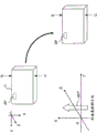
The schematically illustrated DSC1 of Fig. 3 and radio communication device 50.DSC1 can be placed on radio communication device 50.At DSC1, be placed under the state on radio communication device 50, between DSC1 and radio communication device 50, carry out wireless near field communication.
In addition, in DSC1 in the drawings, the position of short-range wireless communication antenna 2 in framework is shown as aerial position 2P, and in addition, the position of short-range wireless communication antenna 51 in radio communication device 50 is shown as aerial position 51P.
Although device must be near each other in wireless near field communication,, more particularly, antenna must be near each other.
Here, radio communication device 50 shown in Figure 3 is connected to for example personal computer, image editing apparatus, image storage unit and out of Memory processing unit or image processing apparatus, and radio communication device 50 can be forwarded to these devices by content file sending from DSC1 etc.Naturally, radio communication device 50 can be plate personal computer, and radio communication device 50 itself can be the forwarding destination of content file etc.
When user attempts to establish a communications link between the radio communication device 50 at DSC1 and communication counterpart, as shown in Figure 3, by DSC1 being placed on radio communication device 5 and by making DSC1 start communication near radio communication device 5.
In wireless near field communication, due to when these communicators enough do not approach each other, the communication between them cannot keep, and therefore conventionally uses at DSC1 and is placed on the method that starts communication under the state on radio communication device 50.In this case, it is unrealistic that user continues to hold DSC1 possibility.
Hereinafter, user holds DSC1 and is placed on and on radio communication device 50, makes the operation communicating between them be called as " Proximity operation ".
In the situation that the Proximity operation by user makes DSC1 mobile as the framework shown in Fig. 3, from the detection signal waveform of the acceleration transducer 20 in DSC1, given shape is as shown in Figure 4 shown.In Fig. 4, suppose that user starts Proximity operation at the time T M0 place of time shaft, and the speed showing in this case changes V and acceleration change AV.
When the beginning of Proximity operation, because DSC1 starts mobilely from halted state, so speed increases, detect on the occasion of acceleration.
Afterwards, when supposition is when framework moves to radio communication device 50 during constant airspeed, although acceleration is depicted as the value that is essentially 0, speed becomes 0 rapidly owing to being placed on radio communication device 5 as DSC1, the acceleration into negative value therefore detected.
That is to say, in the situation that user carries out Proximity operation, because the acceleration transducer 20 of DSC1 detects accekeration as shown in Figure 4, therefore the acceleration observing according to the detection signal waveform that can be used as this value changes information, and the CPU7 of DSC1 can know that DSC1 is in the situation of carrying out Proximity operation.
In the present embodiment, DSC1 makes generation at common time standby radio wave in rough state or halted state.Conventionally time representation DSC1 still determines in power opening state the period that will carry out wireless near field communication especially.Subsequently, when definite Proximity operation for radio communication device 50 is performed, DSC1 produces the standby radio wave in wireless near field communication with high density state in the regular hour.In addition, afterwards, when the regular hour does not connect in the past, standby radio wave is set to non-dense set state or halted state.
Here, make standby radio wave mean to extend in rough state and send standby radio interval wave period (polling cycle).
Although Fig. 6 A shows the example of the polling cycle that produces standby radio wave, high density state represents the situation that polling cycle P is short, and the long situation of rough state representation polling cycle P.
Under high density state, communication party easily detected.On the other hand, although rough state representation detects communication party's the lower state of possibility, do not mean that to detect to be stopped completely yet.
Halted state represents the state that the generation of standby radio wave is stopped completely, and in this case, communication party is not detected.
As the operation in embodiment, conventionally the standby radio wave of time is set to rough state to be still set to halted state unimportant, and these states should arrange according to feature and characteristic that the device of function is installed on it.
In addition, the occurrence of the polling cycle P under high density state and rough state also should arrange according to feature and the characteristic of device.As this routine DSC1, the state that the high density state the following describes and rough state represent respectively to shorten the state of polling cycle P and extend polling cycle P, and to the not restriction of concrete periodic quantity.
In flow chart shown in Figure 5, described concrete processing example, wherein, DSC1 determines that the acceleration causing due to Proximity operation changes and control standby radio wave.
Here, although flow chart shown in Figure 5 is interpreted as the control of the CPU7 of the program based on being carried out by CPU7, process, similarly processing also can be carried out or can with hardware and software, both carry out with hardware.
The in the situation that of DSC1 power-on, as step F 100, CPU7 is controlled at the standby radio wave of common time.That is to say, the halted state that CPU7 produces standby radio wave or rough state are indicated to wireless near field communication controller 10.In response to this, wireless near field communication controller 10 standby radio waves are set to halted state or rough state.
As step F 101, CPU7 obtains acceleration detection signal (acceleration measurement) from acceleration transducer 20, and monitors whether accekeration is equal to or greater than constant threshold thA.In addition, Fig. 4 illustrates the threshold value thB of description after a while and an example of threshold value thA.
The acquisition methods of the detected value of acceleration transducer 20 can be the method for the value of acceleration transducer 20 of being obtained by CPU7 at regular intervals, or can be by interrupting etc. notifying the method for this value from acceleration transducer 20.
In the situation that acceleration measurement is no more than threshold value thA, continue similarly to monitor.
During supervision in step F 101 is processed, in the situation that acceleration measurement surpasses threshold value thA, CPU7 advances to step F 102.In this case, CPU7 is used timer value Ta to count as the limit time started.
Here, exist timer to be comprised in the situation in CPU7 as function, have timer to be implemented as to be different from the situation of the piece of CPU7, any in these situations is all possible.
After time counting starts, when obtaining the acceleration measurement of acceleration transducer 20, the supervision that CPU7 continues in step F 103 and F104 is processed.
In step F 103, whether Looking Out Time counting reaches timer value Ta.In addition,, in step F 104, monitor whether the value of obtaining as acceleration measurement is equal to or less than constant threshold thB.
In the situation that time counting reaches timer value Ta, the supervision that CPU7 turns back to F101 from step F 103 is processed.
In addition, the in the situation that of acceleration measurement being detected at CPU7 be equal to or less than threshold value thB in step F 104, at this regularly, CPU7 evaluates Proximity operation and is performed, thereby determines that communication opportunity is provided.
At F101 in these steps of F104, when in the situation that the negative direction acceleration that produces positive acceleration that the translational speed based on framework increases in the scheduled time (Ta) and stop to the motion of framework, DSC1 determines that framework approaches radio communication device 50 and definite communication opportunity is provided.
That is to say, the positive acceleration measurement of the speed rising when beginning based on Proximity operation is detected and is placed on while negative acceleration measured value further being detected on radio communication device 5 and when speed becomes 0 rapidly at DSC1, and waveform shape shown in Figure 4 is determined and is assessed as Proximity operation.
On the other hand, even if positive acceleration is detected once, afterwards, until timer value Ta all negative acceleration do not detected in the situation that, the movement of the framework of DSC1 is assumed that and is not near operation, and turns back to step F 101.
In the situation that Proximity operation is determined and advance to step F 105, CPU7 is used timer value Tb as the new time started counting of limit.
In addition, CPU7 indication wireless near field communication controller 10 produces standby radio wave with high density state.In response to this, wireless near field communication controller 10 is carried out and is shortened from the polling cycle of short-range wireless communication antenna 2 operation that produces standby radio wave.
In this state, the communication connection of 10 trials of wireless near field communication controller and the opposing party's radio communication device 50.
In step F 106, whether CPU7 Looking Out Time counting reaches timer value Tb.In addition,, in step F 107, monitor whether communication party's device is detected.
That is to say the upper limit time of the sense cycle on communication objective ground when timer value Tb is defined in standby radio wave and is produced with high density state.
In the situation that CPU7 detects communication party in step F 107, advance to step F 108, and CPU7 controls wireless near field communication controller 10 and starts radio communication.
On the other hand, the in the situation that when communication party's device is not detected, time counting reaching timer value Tb, CPU7 advances to F109 from step F 106, and the halted state or the rough state that to wireless near field communication controller 10 indication standby radio waves, produce.In response to this, wireless near field communication controller 10 standby radio waves are set to halted state or rough state.Subsequently, the supervision that CPU7 turns back in step F 101 is processed.
Feature below above-mentioned processing in Fig. 5 has.
-in the common time, CPU7 is controlled at rough state or halted state by standby radio wave.
-according to the acceleration of acceleration detection signal (acceleration measurement) identification by from acceleration transducer 20, change, whether the Proximity operation that CPU7 assessment makes the framework of DSC1 approach radio communication device 50 is performed, and in the situation that Proximity operation is determined, communication opportunity is determined.
-in the situation that communication opportunity is determined, CPU7 is controlled at standby radio wave under high density state.
-make the standby radio wave of high density state only be performed the scheduled time (time value Tb), and if can not set up communication during during this period of time, standby radio wave turns back to common state so, such as rough state and halted state.
In described the first embodiment, realized effect below.
Although described polling cycle P in Fig. 6 A before, communication party in high density state, easily detected, in rough state, be not easy to detect communication party.Under halted state, communication party is not detected.Meanwhile, although the relation between power consumption and polling cycle has been shown in Fig. 6 B, the power consumption relevant with standby is along with it becomes the high density state that polling cycle P is short and improves.In rough state, there is power consumption seldom, in halted state, do not have the power consumption relevant with standby radio wave.
In view of more than, during processing in considering the first embodiment, approach processing and be detected to determine that communication opportunity standby radio wave are set to high density state, and it is set to rough state or halted state in other situation, thereby only make in the situation that user wishes that the possibility of wireless near field communication is high, just can improve the possibility of communication connection.In other words, in the situation that user wishes that the possibility of wireless near field communication is low, can reduce the possibility of communication connection, this is suitable for the situation that prevents that as much as possible undesirable communication is performed.
In addition, only in user wishes situation that the possibility of wireless near field communication is high, the high density state with power consumption is set, and the halted state of the less rough state of power consumption or not relevant with standby radio wave power consumption is set in other situation, this is effective for reducing the power consumption relevant with standby.
In addition, only standby radio wave is set to high density state to reach the scheduled time (timer value Tb) is also effective.Although user's Proximity operation determines according to acceleration measurement, Proximity operation needn't be restricted to " DSC1 is placed on to the operation on radio communication device 50 ".
For example, in conventionally user uses, operation DSC1 being placed on desk etc. by user is performed repeatedly.
Here, when considering average service conditions, in the situation that user uses DSC1 and place it on desk etc., because its power supply is in many cases closed, therefore in these cases, the processing in Fig. 5 above-mentioned is not performed.But, depend on the circumstances, there is such situation: when the electric power starting of DSC1, user is placed on DSC1 on desk etc.In this case, by the determining of acceleration measurement, can observe essentially identical waveform as shown in Figure 5, and can determine communication opportunity.Then, when communication party is not detected, standby radio wave is produced with high density state.
In this example, because the time with timer value Tb produces the standby radio wave of the high density state that wherein communication party can not be detected as limit, therefore in the situation that it can not detect communication party in being simply placed on the state on desk, can not rest on indefinitely under high density state, but after certain hour, turn back to rough state or halted state.
That is to say, in this example, when determining while existing user to wish the high likelihood of wireless near field communication, standby radio wave is also set to high density state, even if in fact user does not wish communication, can not rest under high density state lavishly indefinitely, but turn back to rough state or halted state yet.By this means, even can not carry out according to acceleration detection completely definite that user's communication is intended to, also power consumption can be suppressed to minimum needs.
In addition, in this example, for user, when DSC1 being placed on to Proximity operation on radio communication device 50 and being performed, carry out radio communication, and, such as owing to content file etc. can being sent to radio communication device 50 1 sides, therefore can be in the situation that not to the extra operation burden of user add, keep convenience.
In addition, other situation about Proximity operation outside the time, standby radio wave is set to rough state and is still set to halted state and can decides according to device, but the effect below obtaining.
For the reduction of power consumption, in the situation that rough state is set up, ratio is more unfavorable in the situation that halted state is set up.But, there is an advantage, that is, even common time of not determined at Proximity operation also retained the possibility of communication connection.According to circumstances, even in the situation that the waveform of the acceleration detection signal observing is different from the waveform of above-mentioned Fig. 4, also exist user to wish the situation of communication.
That is to say, when user's execution makes DSC1 approach the operation of radio communication device 50 grades, CPU7 can not detect it.At DSC1 and corresponding radio communication device 50, be while thering is the device of such use state, rough state be set conventionally and it is suitable at least retaining the possibility that can establish a communications link.
On the other hand, when common set of time halted state by time, for reducing power consumption, be favourable.In addition, when being provided with halted state, user is not wished to the communication of carrying out exists high preventing effectiveness.But, on the contrary, in the situation that requiring to communicate, require user to carry out specific Proximity operation.
Therefore, in the situation that DSC1 and corresponding radio communication device 50 only communicate by specific Proximity operation, in common set of time halted state, be, suitable.
<3. according to the Control on Communication of the second embodiment, process >
The Control on Communication according to the second embodiment that description is undertaken by DSC1 is processed.
In a second embodiment, acceleration transducer 20 detects the accekeration of waveform shown in Fig. 4 the three-dimensional of sense acceleration generation direction.
More particularly, acceleration transducer 20 does not detect the accekeration as scalar value, but detects the accekeration as vector value, and can detect the amount of acceleration on three-dimensional.
For example, in the situation that user carries out the Proximity operation shown in above-mentioned Fig. 3, about contiguous acceleration detection direction constantly, when the top of using as shown in Figure 7 DSC1 always defines X-axis, Y-axis and Z axis as the pros of X-axis, the acceleration (acceleration detection direction DET) in the negative direction of X-axis detected.
Here, in Fig. 7 (and the Fig. 8 the following describes, Fig. 9 and Figure 11), arrow U illustrates the upper surface side of DSC1, and arrow B illustrates the basal surface side of DSC1.
As shown in the 2P of position, suppose that the position of short-range wireless communication antenna 2 is disposed in the basal surface side of DSC framework.
In this example, when the execution of certain Proximity operation being detected according to accekeration, this in moment simultaneously sense acceleration direction to determine the direction of carrying out Proximity operation.By these means, compare with the method in the first embodiment, can detect more accurately user and whether wish to start communication.
A concrete example is described.
According to the example of Fig. 7, the direction that DSC1 approaches communication party's radio communication device 50 is the negative direction of the X-direction of DSC1.Because the short-range wireless communication antenna 2 of DSC1 is present on the basal surface of DSC1, so the radio antenna 51(position 51P of it and radio communication device 5) adjacent, and think that user wishes to start communication.
Meanwhile, as shown in the example of Fig. 8, with the acceleration of the upper and lower relative direction of Fig. 7, that is, acceleration detection direction DET is the acceleration of the positive direction of X-direction, can be detected.
In example in Fig. 8, as the waveform of the acceleration of scalar value, be similar to the waveform of Proximity operation.But if there is radio communication device 50, the approaching direction of radio communication device 50 is the upper surface side contrary with the installation direction (as the position 2P of basal surface side) of the short-range wireless communication antenna 2 of DSC1 so.
Conventionally, unlikely think that user makes significantly DSC1 turn upside down and carries out the Proximity operation for communication party, and it is low to think that user wishes to start the possibility of communication.
In addition, as shown in the example of Fig. 9, may there is following situation: in the direction of longitudinally being placed at DSC1, acceleration detected.This is that acceleration detection direction DET is the situation of the positive direction of Y direction.
In the example of Fig. 9, as the waveform of the acceleration of scalar value, be similar to the waveform of Proximity operation, but direction does not correspond to the installation direction (position 2P) of the short-range wireless communication antenna 2 of DSC1.Conventionally, do not think that user longitudinally places DSC1 and carries out Proximity operation, and it is low to think that user wishes to start the possibility of communication.
If Fig. 7 is to as shown in the example of Fig. 9, following the acceleration direction of communication while starting to carry out Proximity operation is the determining positions of the antenna near field communication device, and in the situation that the direction of the acceleration of this direction when Proximity operation being detected is mated, can determine that user wishes to start communication.
Therefore, consider such acceleration directional information, in the situation that having determined that user wishes to start communication, standby radio wave is sent certain hour with high density state.Otherwise standby radio wave is set to rough state or halted state.By this means, can prevent the undesirable communication of user and reduce the power consumption for standby radio wave.
Figure 10 illustrates according to the Control on Communication of the CPU7 of the second embodiment and processes.
Here, in Figure 10, because step F 100 is similar to Fig. 5 to step F 104 and step F 105 to step F 109, therefore omit the explanation repeating.This Figure 10 illustrates the processing example in the step that step F 110 is added to Fig. 5.
In the processing of Figure 10, first, in step F 100, in step F 104, CPU7 determines Proximity operation by the waveform of the acceleration as scalar value.Subsequently, in the situation that determine that it is corresponding to the Proximity operation about described scalar, in step F 110, whether CPU7 determination of acceleration direction mates with antenna installation direction.
In the situation that Fig. 7, to the example of describing in Fig. 9, when acceleration detection direction DET is the negative direction of X-axis, determines their couplings.
On the other hand, in the situation that acceleration detection direction DET is the positive direction of X-axis, determination of acceleration direction is not mated with antenna installation direction.
In addition,, as described in Figure 11 after a while, having acceleration detection direction DET is the positive direction of Z axis or the situation of negative direction.This is that front surface or the rear surface of following situation: DSC1 is placed on the upper surface of radio communication device 50.In this case, communication is all possible in many cases, or supposition is as considered above the situation that user can place with communicating.Therefore, in the situation that being arranged and having, the short-range wireless communication antenna 2 of supposition DSC1 makes the performance that can communicate under state shown in Figure 11, when acceleration detection direction DET is the positive direction of Z axis or negative direction, can determination of acceleration direction mate with antenna installation direction.Or, in this case, can determine that they do not mate.In the situation that the positive direction of Z axis or negative direction, determining in step F 110 can decide according to the performance of this device and behaviour in service etc.
In step F 110, determined that in acceleration direction and the unmatched situation of antenna installation direction, CPU7 turns back to step F 101.That is to say, suppose that user wishes that the possibility communicating is low, and standby radio wave is not set to high density state.
On the other hand, in step F 110, determined that the in the situation that acceleration direction being mated with antenna installation direction, CPU7 advances to step F 105.That is to say, think that user wishes that the high and communication opportunity of possibility of communication is provided, standby radio wave is set to high density state.Step F 105 is similar to the first embodiment to the processing in step F 109.
As mentioned above, according to the second embodiment, CPU7 identifies acceleration change information and the three-dimensional acceleration directional information of the acceleration about producing according to the acceleration detection signal being obtained by acceleration transducer 20.Subsequently, according to acceleration change information and acceleration directional information, in the situation that estimating framework and approaching radio communication device 50 with specific acceleration direction state, communication opportunity determined, and standby radio wave is set to high density state and reaches certain hour (during timer value Tb).
According to the second embodiment that is similar to the first embodiment, when keeping user's convenience, can save electric power and be prevented the effect of unnecessary communication.Especially by strengthening definite precision of telex network intention, can further improve these effects.
<4. according to the Control on Communication of the 3rd embodiment, process >
The Control on Communication according to the 3rd embodiment that description is undertaken by DSC1 is processed.
In being similar to the 3rd embodiment of above-mentioned the second embodiment, according to acceleration change information, carrying out and closely operate and assess the intention that user starts to communicate by letter with acceleration directional information.In addition, in the 3rd embodiment, in the situation that thinking that user wishes to start communication, inappropriate owing to placing the mode of framework of DSC1, therefore antenna direction detected incorrect, and carry out demonstration or voice informing, thus modes of emplacement is corrected, so that antenna direction is followed communication party's short-range wireless communication antenna.
Example with reference to above-mentioned Fig. 7, owing to approaching the negative direction of X-direction and the short-range wireless communication antenna of DSC1 2 that communication party's direction is DSC1, be present on the basal surface of DSC1, so it approaches the antenna 51 of radio communication device 50 and thinks that user wishes to start communication.
Meanwhile, be similar to the example of Figure 11, the situation that exists DSC1 to be placed in a horizontal manner.In this example, although be the waveform as Proximity operation as the waveform of the acceleration of scalar,, when this direction is the positive direction of Z axis and user while wishing to start to communicate by letter, can not think that the direction of short-range wireless communication antenna 2 is not suitable for starting communication.
Under state shown in Figure 11, depend on the communication performance of this device, owing to not approaching communication party's short-range wireless communication antenna 51, therefore, even if user wishes to communicate, radio wave situation is also bad, therefore has the possibility disconnecting.
In the 3rd embodiment, carry out and show or voice informing in this case, thereby modes of emplacement is corrected, so that antenna direction is followed communication party's short-range wireless communication antenna 51.By this means, attitude and the raising of encouraging user to proofread and correct DSC1 make radio wave possibility in shape.
Figure 12 illustrates according to the Control on Communication of the CPU7 of the 3rd embodiment and processes.
Here, in Figure 12, step F 100 is similarly to process with Fig. 5 to step F 104 and step F 105 to step F 109, and step F 110 is the processing that are similar to Figure 10.
Figure 12 is the processing example that step F 111 and step F 112 are added to the step of Figure 10.
In this Figure 12, first, in step F 100, in step F 104, CPU7 is usingd the mode identical with the second embodiment with the first embodiment and is determined Proximity operation by the waveform of the acceleration as scalar.Subsequently, be similar to the second embodiment, at definite this scalar, corresponding to Proximity operation in the situation that, in step F 110, whether CPU7 determination of acceleration direction mates with antenna installation direction.
But, in step F 110, as shown in the example of Fig. 7, only determine them in the situation that the negative direction that acceleration detection direction DET is X-axis is mated in this case, otherwise determine that they do not mate.
That is to say, be the positive direction of X-axis, in the positive direction of the axle of the positive direction of Y-axis or negative direction or Z or negative direction situation, determine that antenna direction does not mate at acceleration detection direction DET.
In the unmatched situation of definite antenna direction, whether CPU7 advances to step F 111 determination of acceleration direction perpendicular to antenna installation direction.Perpendicular to antenna installation direction representation case, as being similar to the situation of Figure 11, that is, acceleration detection direction DET is the positive direction of Z axis or the situation of negative direction.
In step F 111, in the situation that determination of acceleration direction is not orthogonal to antenna installation direction, that is to say, in the situation that acceleration detection direction DET is the positive direction of X-axis or the positive direction of Y-axis or negative direction, CPU7 turns back to step F 101.That is to say, determine that user wishes that the possibility of communication is low, standby radio wave is not set to high density state.
On the other hand, the in the situation that of having determined acceleration direction perpendicular to antenna installation direction in step F 111, CPU7 advances to step F 112.Subsequently, CPU7 carries out user's attention is informed.
For example, in display unit 3, be similar to " in the situation that carrying out radio communication, please make basal surface approaching face to device " alert message shown, or from alert message voice like voice-output unit 12 output classes.Or, from voice-output unit 12, produce electronics sound.Alert message in display unit 3 shows and can carry out with together with the output of alert message voice and electronics sound.
When the such warning of execution is informed, CPU7 advances to step F 105.Here, in step F 110, determined that the in the situation that acceleration direction being mated with antenna installation direction, CPU7 also advances to step F 105 and subsequent step.
That is to say, in these cases, determine that user wishes that the possibility of communication is high, standby radio wave is set to high density state.Step F 105 is similar to the first embodiment and the second embodiment to the processing in step F 109.
As mentioned above, according to the 3rd embodiment, in the situation that CPU7 evaluates the framework of DSC1 according to acceleration change information and acceleration directional information, with specific acceleration direction state, approach the external communication device such as radio communication device 50, according to the position relationship between the antenna direction of DSC1 and radio communication device 50 etc., carry out and inform output.
Especially the antenna direction of DSC1 and position relationship between radio communication device 50 be can communicate by letter but be not under optimum state, when evaluate the framework of DSC1 and radio communication device 50 mutually near time, communication opportunity is determined and is performed from the warning output of display unit 3 or voice-output unit 11.
By this means, it is inappropriate for communication that user can understand modes of emplacement, and in the situation that hope is communicated by letter, estimate to proofread and correct the mode of placing DSC1.In this case, suppose and can under good wireless status, communicate by letter.
<5. according to the Control on Communication of the 4th embodiment, process >
The 4th embodiment is described.Although the 4th embodiment is substantially identical with the 3rd above-mentioned embodiment, added the processing of proofreading and correct the situation of the mode of placing DSC1 corresponding to user.
Although Figure 13 shows the Control on Communication of CPU7 and processes, owing to being added Figure 13 except step F 113 and step F 114, be similar to Figure 12, so only provide the explanation about step F 113 and step F 114.
As explained in the 3rd embodiment, exist in step F 112 according to how placing the situation that DSC1 carrys out notification alert message.
In this case, although from the timing of step F 105 bring into use timer value Tb as limit within a certain period of time standby radio wave be set to high density state, if but inappropriate with the mode of the similar placement of Figure 11 DSC1, the possibility that can not connect is so high.
Therefore,, although user is notified, for the corresponding of user, regularly do not determined.When user proofreaies and correct the attitude of DSC1, at this regularly, time counting can reach timer value Tb.For example, in step F 109, be for halted state rather than rough state in the situation that, may there is following situation: although user has proofreaied and correct the attitude of DSC1, still cannot communicate.
Therefore, in this example, CPU7 standby radio wave in step F 105 is set to high density state, and after time started counting, in step F 113, CPU7 monitors the attitude updating of DSC1 according to acceleration change information and acceleration directional information.
Here, in the time communication party's state continuance can not being detected, exist user according to informing in step F 112, to proofread and correct the situation of the attitude of DSC1.When detecting that the attitude of DSC is corrected and the state of Figure 11 is corrected as the state of Fig. 7, CPU7 advances to step F 114 and from the beginning restarts to the time counting of timer value Tb.
By this, process, when the attitude of DSC1 is corrected, the high density state of standby radio wave, from this timing certain time, can improve the precision of connection setup.
<6. modified example >
Although described hereinbefore embodiment, communication device configured of the present disclosure and Control on Communication are processed and are not limited to these embodiment, and can have various modified examples.
For determining of the Proximity operation that uses acceleration detection value to be undertaken by acceleration change, in each embodiment, acceleration detection waveform about Fig. 4 detects positive direction acceleration, afterwards, in scheduled time Ta, detect negative direction acceleration (step F 101 of each Control on Communication processing is to step F 104).
Definite method of Proximity operation is not limited to this, (a) and (b) below and (c) be all possible.
(a), in scheduled time Ta, from positive direction acceleration detected and negative direction acceleration detected after starting during zero passage acceleration in the situation that, Proximity operation is determined.
(b) positive direction acceleration in scheduled time Ta, detected, negative direction acceleration detected afterwards.In addition, afterwards, when being held certain hour during zero acceleration (, the state after being placed on radio communication device 50 is held), Proximity operation is determined.
(c) in scheduled time Ta, detect after positive direction acceleration, after during zero passage acceleration, negative direction acceleration detected.In addition, afterwards, when being held certain hour during zero acceleration (, the state after being placed on radio communication device 50 is held), Proximity operation is determined.
Therefore, although this is an example, for determining that the whole bag of tricks of Proximity operation is all possible.Naturally, can arrange between the time conditions that limits during each and the window phase between detection period etc., and carry out more accurately to approach and determine.
In addition,, as the acceleration detection value from acceleration transducer 20 actual outputs, supposition can be by filtering fully for the definite noise component of Proximity operation naturally.
In addition, in these embodiments, although Proximity operation represents the Proximity operation on radio communication device 50 by DSC1 " placement ", and this is to determine according to the waveform of acceleration measurement as shown in Figure 4, but the operator scheme of user's Proximity operation changes according to actual behaviour in service and type of device etc.
For example, there is device corresponding to the opposing party of radio communication device 50 on wall surface and make to approach corresponding to the communication equipment of DSC1 etc. the situation of this device.
Therefore, for Proximity operation, determine, should carry out to approach by the corresponding waveforms detection that the type of practical communication equipment, form and behaviour in service are taken into account and determine.
In these embodiments, although DSC1 is used as the example of communication equipment, provide, naturally, be not limited to DSC1, can in various devices, realize communication equipment of the present disclosure.
For example, portable phone, camera system, mobile terminal apparatus, portable type game device, messaging device, portable music player, portable TV receiver and other various devices are all possible.From detecting and the viewpoint of the translational acceleration of determining device itself, the dingus that can be held by user's hand is applicable to, but need not be confined to this.
In the situation that these various devices are implemented as communication equipment 100 of the present disclosure, these devices only need to comprise the configuration of Figure 14.
Figure 14 illustrates control unit 101, acceleration transducer 102, wireless near field communication controller 103 and short-range wireless communication antenna 104.
As carrying out the wireless near field communication unit of wireless near field communication with external communication device, wireless near field communication controller 103 and short-range wireless communication antenna 104 are provided.
The acceleration transducer 102 of the acceleration of the movement that detects framework is provided in addition.
Present technique can also be configured as follows.
(1) communication equipment, comprising:
Wireless near field communication unit, carries out the wireless near field communication with external communication device;
Acceleration transducer, the movement by framework carrys out sense acceleration; And
Control unit, the acceleration change information of identifying according to the acceleration detection signal by from acceleration transducer comes appraisal framework whether to approach external communication device, by the result of assessment, come executive communication chance to determine, in the situation that communication opportunity is determined, control wireless near field communication unit and produce standby radio wave with high density state, and in other situation the situation except definite described communication opportunity, the generation of the standby radio wave of wireless near field communication unit is controlled to rough state or halted state.
(2) according to the communication equipment (1) described, wherein, in the situation that produced standby radio wave with high density state and do not had to set up and communicate by letter with external communication device through the scheduled time by definite wireless near field communication unit of controlling of communication opportunity, control unit is controlled at rough state or halted state by the generation of the standby radio wave of wireless near field communication unit.
(3) according to the communication equipment (1) or (2) described, wherein, in the situation of the negative direction acceleration that produces in the given time the positive direction acceleration that promotes based on translational speed and stop to the movement of framework as acceleration change information, control unit determines that framework approaches external communication device.
(4) according to the communication equipment of any one in (1) to (3),
Wherein, according to the acceleration detection signal being obtained by acceleration transducer, the three-dimensional acceleration directional information that control unit identification produces for further acceleration, and
Wherein, in the situation that control unit evaluates framework and approaches external communication device with specific acceleration direction state according to acceleration change information and acceleration directional information, control unit is determined described communication opportunity.
(5) according to the communication equipment (4) described, also comprise:
Inform output unit,
Wherein, in the situation that control unit evaluates framework and approaches external communication device with specific acceleration direction state according to acceleration change information and acceleration directional information, control unit is carried out the output of informing of informing output unit according to the position relationship between the antenna direction of wireless near field communication unit and external communication device.
Reference numerals list
1?DSC
2,104 short-range wireless communication antennas
3 display units
4 operation input units
5 image capture unit
6 picture catching signal processing units
7?CPU
8 main storages
9 storage areas
10,103 wireless near field communication controllers
11 flash memories
12 voice-output units
20,102 acceleration transducers
50 radio communication devices
51 short-range wireless communication antennas
100 communication equipments
101 control units
Claims (6)
1. a communication equipment, comprising:
Wireless near field communication unit, carries out the wireless near field communication with external communication device;
Acceleration transducer, detects by the acceleration of the movement of framework; And
Control unit, the acceleration change information of identifying according to the acceleration detection signal by from acceleration transducer comes appraisal framework whether to approach external communication device, by the result of assessment, come executive communication chance to determine, in the situation that communication opportunity is determined, control wireless near field communication unit and produce standby radio wave with high density state, and in other situation the situation except definite described communication opportunity, the generation of the standby radio wave of wireless near field communication unit is controlled to rough state or halted state.
2. communication equipment according to claim 1, wherein, in the situation that produced standby radio wave with high density state and do not had to set up and communicate by letter with external communication device through the scheduled time by definite wireless near field communication unit of controlling of communication opportunity, control unit is controlled at rough state or halted state by the generation of the standby radio wave of wireless near field communication unit.
3. communication equipment according to claim 1, wherein, in the situation of the negative direction acceleration that produces in the given time positive direction acceleration that translational speed based on framework rises and stop to the movement of framework as acceleration change information, control unit determines that framework approaches external communication device.
4. communication equipment according to claim 1,
Wherein, according to the acceleration detection signal being obtained by acceleration transducer, the three-dimensional acceleration directional information that control unit identification produces for further acceleration, and
Wherein, in the situation that control unit evaluates framework and approaches external communication device with specific acceleration direction state according to acceleration change information and acceleration directional information, control unit is determined described communication opportunity.
5. communication equipment according to claim 4, also comprises:
Inform output unit,
Wherein, in the situation that control unit evaluates framework and approaches external communication device with specific acceleration direction state according to acceleration change information and acceleration directional information, control unit is carried out from the output of informing of informing output unit according to the position relationship between the antenna direction of wireless near field communication unit and external communication device.
6. a communication control method that comprises the communication equipment of wireless near field communication unit and acceleration transducer, the wireless near field communication with external communication device is carried out in this wireless near field communication unit, this acceleration transducer detects by the acceleration of the movement of framework, and described communication control method comprises:
The acceleration change information of identifying according to the acceleration detection signal by from acceleration transducer comes appraisal framework whether to approach external communication device, by the result of assessment, come executive communication chance to determine, and from wireless near field communication unit with high density state, produce standby radio wave in the situation that communication opportunity is determined; And
In other situation the situation except definite described communication opportunity, the generation of the standby radio wave of wireless near field communication unit is arranged on to rough state or halted state.
Applications Claiming Priority (3)
| Application Number | Priority Date | Filing Date | Title |
|---|---|---|---|
| JP2011-152746 | 2011-07-11 | ||
| JP2011152746A JP5807414B2 (en) | 2011-07-11 | 2011-07-11 | Communication device and communication control method |
| PCT/JP2012/064917 WO2013008572A1 (en) | 2011-07-11 | 2012-06-11 | Communication device, communication control method |
Publications (1)
| Publication Number | Publication Date |
|---|---|
| CN103636266A true CN103636266A (en) | 2014-03-12 |
Family
ID=47505870
Family Applications (1)
| Application Number | Title | Priority Date | Filing Date |
|---|---|---|---|
| CN201280033172.8A Pending CN103636266A (en) | 2011-07-11 | 2012-06-11 | Communication device, communication control method |
Country Status (6)
| Country | Link |
|---|---|
| US (1) | US9326120B2 (en) |
| EP (1) | EP2733994A1 (en) |
| JP (1) | JP5807414B2 (en) |
| KR (1) | KR20140036254A (en) |
| CN (1) | CN103636266A (en) |
| WO (1) | WO2013008572A1 (en) |
Cited By (1)
| Publication number | Priority date | Publication date | Assignee | Title |
|---|---|---|---|---|
| CN111667609A (en) * | 2019-03-07 | 2020-09-15 | 意法半导体股份有限公司 | Three-level motion detector using accelerometer device in key card applications |
Families Citing this family (3)
| Publication number | Priority date | Publication date | Assignee | Title |
|---|---|---|---|---|
| JP2015126410A (en) * | 2013-12-26 | 2015-07-06 | アプリックスIpホールディングス株式会社 | Transmitter and program |
| JP6398375B2 (en) * | 2014-06-30 | 2018-10-03 | カシオ計算機株式会社 | COMMUNICATION DEVICE, COMMUNICATION METHOD, AND PROGRAM |
| JP6152242B2 (en) * | 2015-04-06 | 2017-06-21 | レノボ・シンガポール・プライベート・リミテッド | Method for ensuring information security of portable electronic device, portable electronic device and function expansion device |
Citations (2)
| Publication number | Priority date | Publication date | Assignee | Title |
|---|---|---|---|---|
| CN101674407A (en) * | 2008-09-12 | 2010-03-17 | 奥林巴斯映像株式会社 | A portable apparatus |
| CN101964673A (en) * | 2009-07-24 | 2011-02-02 | 索尼公司 | Communication device, communication scheme determination method, and program |
Family Cites Families (8)
| Publication number | Priority date | Publication date | Assignee | Title |
|---|---|---|---|---|
| JP2008154004A (en) | 2006-12-18 | 2008-07-03 | Sony Ericsson Mobilecommunications Japan Inc | Portable terminal and information communicating method |
| US8391786B2 (en) * | 2007-01-25 | 2013-03-05 | Stephen Hodges | Motion triggered data transfer |
| JP2009278267A (en) * | 2008-05-13 | 2009-11-26 | Sony Corp | Communication equipment, communication system, communication method, and program |
| JP5495582B2 (en) | 2009-02-25 | 2014-05-21 | Necパーソナルコンピュータ株式会社 | Wireless communication apparatus, wireless communication system, control method, and program |
| KR101645461B1 (en) * | 2010-01-12 | 2016-08-12 | 삼성전자주식회사 | Apparatus and method for auto conntecting wlan in portable terminal |
| JP5471653B2 (en) | 2010-03-17 | 2014-04-16 | 日産自動車株式会社 | Permanent magnet type electric motor |
| EP2485542B1 (en) * | 2011-02-03 | 2019-02-27 | Sony Corporation | Portable electronic device and operation method for establishing a near field communication link |
| US8965285B2 (en) * | 2011-05-13 | 2015-02-24 | Nokia Corporation | Touch inquiry |
-
2011
- 2011-07-11 JP JP2011152746A patent/JP5807414B2/en not_active Expired - Fee Related
-
2012
- 2012-06-11 US US14/125,474 patent/US9326120B2/en active Active
- 2012-06-11 CN CN201280033172.8A patent/CN103636266A/en active Pending
- 2012-06-11 WO PCT/JP2012/064917 patent/WO2013008572A1/en active Application Filing
- 2012-06-11 KR KR1020137034091A patent/KR20140036254A/en not_active Application Discontinuation
- 2012-06-11 EP EP12812116.7A patent/EP2733994A1/en not_active Withdrawn
Patent Citations (2)
| Publication number | Priority date | Publication date | Assignee | Title |
|---|---|---|---|---|
| CN101674407A (en) * | 2008-09-12 | 2010-03-17 | 奥林巴斯映像株式会社 | A portable apparatus |
| CN101964673A (en) * | 2009-07-24 | 2011-02-02 | 索尼公司 | Communication device, communication scheme determination method, and program |
Cited By (2)
| Publication number | Priority date | Publication date | Assignee | Title |
|---|---|---|---|---|
| CN111667609A (en) * | 2019-03-07 | 2020-09-15 | 意法半导体股份有限公司 | Three-level motion detector using accelerometer device in key card applications |
| US11721202B2 (en) | 2019-03-07 | 2023-08-08 | Stmicroelectronics S.R.L. | Three-level motion detector using accelerometer device in key fob application |
Also Published As
| Publication number | Publication date |
|---|---|
| KR20140036254A (en) | 2014-03-25 |
| US20140113566A1 (en) | 2014-04-24 |
| EP2733994A1 (en) | 2014-05-21 |
| JP2013021475A (en) | 2013-01-31 |
| US9326120B2 (en) | 2016-04-26 |
| JP5807414B2 (en) | 2015-11-10 |
| WO2013008572A1 (en) | 2013-01-17 |
Similar Documents
| Publication | Publication Date | Title |
|---|---|---|
| US20120155848A1 (en) | Method and System for Providing Viewfinder Operation in Mobile Device | |
| JP6468278B2 (en) | COMMUNICATION CONTROL DEVICE, COMMUNICATION CONTROL METHOD, AND PROGRAM | |
| JP6020353B2 (en) | Information processing apparatus, image forming apparatus, remote operation method, remote control method, remote operation program, and remote control program | |
| CN105050115A (en) | Method and device for waking up MCU | |
| CN103458190A (en) | Photographing method, photographing device and terminal device | |
| WO2019129020A1 (en) | Automatic focusing method of camera, storage device and mobile terminal | |
| CN103702029A (en) | Method and device for prompting focusing during shooting | |
| CN105738921A (en) | Method and device used for acquiring position information | |
| WO2018195708A1 (en) | Image sharing method and electronic device | |
| CN103636266A (en) | Communication device, communication control method | |
| US9706101B2 (en) | Image processing terminal, imaging machine, information processing method, program, and remote imaging system to remotely operate the imaging machine | |
| CN105099526A (en) | Method and device for transmitting polling data package | |
| US9191896B2 (en) | Communication apparatus and communication control method | |
| KR20170120707A (en) | METHOD, APPARATUS, PROGRAM AND RECORDING MEDIUM FOR PROVIDING POINT REPORTING OF TAPS | |
| CN109561255B (en) | Terminal photographing method and device and storage medium | |
| JP2010068494A (en) | Portable device | |
| CN110912830A (en) | Method and device for transmitting data | |
| CN114785766B (en) | Control method, terminal and server of intelligent equipment | |
| JP2017092645A (en) | Radio communications system, information processing method, and program | |
| CN114596633A (en) | Sitting posture detection method and terminal | |
| JP2009239704A (en) | Data management system and server apparatus | |
| JP2019041187A (en) | Portable terminal and system | |
| CN111567019B (en) | Recording medium and electronic device | |
| JP2009253511A (en) | Electronic device, and data communication method | |
| JP6404300B2 (en) | Electronic device, control method of electronic device, and program |
Legal Events
| Date | Code | Title | Description |
|---|---|---|---|
| PB01 | Publication | ||
| PB01 | Publication | ||
| C10 | Entry into substantive examination | ||
| SE01 | Entry into force of request for substantive examination | ||
| WD01 | Invention patent application deemed withdrawn after publication | ||
| WD01 | Invention patent application deemed withdrawn after publication |
Application publication date: 20140312 |