CN103519585A - Drawer guide rail structure - Google Patents
Drawer guide rail structure Download PDFInfo
- Publication number
- CN103519585A CN103519585A CN201210229003.3A CN201210229003A CN103519585A CN 103519585 A CN103519585 A CN 103519585A CN 201210229003 A CN201210229003 A CN 201210229003A CN 103519585 A CN103519585 A CN 103519585A
- Authority
- CN
- China
- Prior art keywords
- rail
- mid
- ball
- bending part
- bilge
- Prior art date
- Legal status (The legal status is an assumption and is not a legal conclusion. Google has not performed a legal analysis and makes no representation as to the accuracy of the status listed.)
- Pending
Links
Images


Landscapes
- Drawers Of Furniture (AREA)
Abstract
The invention belongs to hardware products, and relates to a drawer guide rail structure. The drawer guide rail structure comprises a fixed rail, a middle rail and a movable rail, and a first rolling way is arranged on the horizontal side of the bearing portion of the fixed rail. A second rolling way is arranged on the horizontal side of the middle rail, and a first ball is arranged between the first rolling way and the second rolling way. A rolling column is arranged between the lower surface of the horizontal side of the movable rail and the upper surface of the horizontal side of the middle rail. First bent portions are arranged at the lower ends of the two vertical sides of the movable rail. The two downward sides at the two ends of the horizontal side of the middle rail are respectively provided with a second bent portion, a third bent portion and a fourth bent portion from top to bottom in sequence, and second balls are embedded between the second bent portions and the first bent portions. Third balls are embedded between the third bent portions and the triangular inclined sides of the fixed rail, and the fourth bent portions start to be bent from the tail ends of the third bent portions and extend towards to the outer sides of the downward sides of the middle rail. The drawer guide rail structure increases the bearing capacity of the middle rail, a guide rail is made to operate more smoothly, the overall deflection of a drawing cabinet is reduced, and the drawer guide rail structure is suitable for being arranged on furniture for use.
Description
Technical field
The present invention relates to hardware, particularly a kind of furniture guide rail.
Background technology
Common drawer guideway is comprised of retaining rail and active rail, and in order to improve bearing capacity and the smoothness of guide rail, manufacturer constantly improves guide rail structure.
The patent of invention (applying date 2012-04-01, application number 2012100952763) that name is called " guide rail structure of drawer " discloses a kind of drawer guideway, it comprises retaining rail and is enclosed in the active rail of retaining rail outside, the supporting part of retaining rail has del cross section, the cross section of active rail is roughly П shape, between retaining rail and active rail, has retainer; The horizontal sides upper surface of retaining rail supporting part has the first raceway of depression; The horizontal sides lower surface of active rail also has the second raceway of depression, and between the first raceway and the second raceway, assembly has the first ball; There is first fold turn of bilge active rail two upstanding edge lower ends; Two first fold turn of bilges of active rail are relative with two triangle hypotenuses of retaining rail respectively, and between every triangle hypotenuse of each first fold turn of bilge and retaining rail, assembly has the second ball respectively; The first ball and the second ball are all held frame and retrain.
This product has been used the ball of lesser amt and the retaining rail of roller and triangular-section, has advantages of that simple structure, saving material and production cost are low.
But in actual application, find that there is individual product when drawer intensity of load is larger, guide rail degradation, reason is the first fold turn of bilge end undercapacity of active rail, there will be expendable deformation to cause the gap between ball and track to increase under the extruding of the second ball.
The deficiency of this product needs improvement.
Summary of the invention
The object of the invention is to overcome the shortcoming of existing guide rail product, provide a kind of load capacity large, solid and reliable guide rail structure of drawer.
The present invention includes retaining rail, mid-rail and active rail, the supporting part of retaining rail has del cross section, and the cross section of mid-rail and active rail is all П shape roughly, has the first retainer between retaining rail and mid-rail; Between mid-rail and active rail, there is the second retainer;
The horizontal sides upper surface of retaining rail supporting part has the first raceway; The horizontal sides lower surface of mid-rail has and also has the second raceway, between the first raceway and the second raceway, is embedded with the first ball; The roller that has horizontal positioned between the horizontal sides lower surface of active rail and the upper surface of mid-rail horizontal sides; There is first fold turn of bilge two upstanding edge lower ends of active rail;
Two lower flaps that are connected to mid-rail horizontal sides two ends are all shaped with the second bending part, the 3rd bending part and four fold turn of bilge from top to bottom successively, the second bending part is relative with the first fold turn of bilge of active rail, between the second bending part and first fold turn of bilge, is embedded with the second ball; The 3rd bending part is relative with the triangle hypotenuse of retaining rail, between each the 3rd bending part and the triangle hypotenuse of the rail that is relatively fixed, is embedded with respectively the 3rd ball, and the second ball and roller are all retrained by the second retainer; The 3rd ball and the first ball are all retrained by the first retainer; Four fold turn of bilge extends since the end bending of the 3rd bending part and to the outside of flap under mid-rail.
Guide rail structure compared with prior art, the present invention has increased a four fold turn of bilge in two lower flap lower ends of mid-rail, two of left and right four fold turn of bilge has been equivalent to increase in the lower end of two lower flaps of mid-rail two reinforcements of arranging along mid-rail length direction, improved significantly the rigidity of two sagging edge tails of mid-rail, the bearing capacity of rail in increase, make guide rail operation more smooth, take out the whole deflection of cabinet and reduce.
Suitable being arranged on all furniture of the present invention used.
Accompanying drawing explanation
Fig. 1 is the cross-sectional view of certain existing guide rail;
Fig. 2 is the structural representation of certain existing guide rail;
Fig. 3 is the cross-sectional view of another kind of existing guide rail;
Fig. 4 is the structural representation of another kind of existing guide rail;
Fig. 5 is the guide rail schematic cross-section of first embodiment of the invention;
Fig. 6 is the guide rail structure schematic diagram of the first embodiment;
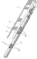
Fig. 7 is the outside drawing of the first embodiment;
Fig. 8 is that the first embodiment removes the outside drawing after active rail;
Fig. 9 is that the first embodiment removes the outside drawing after active rail and the second retainer;
Figure 10 is the guide rail cross-sectional view of the second embodiment.
The specific embodiment
Below in conjunction with drawings and Examples, further illustrate the present invention.
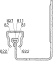
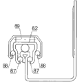
Fig. 1 and Fig. 2 are structures of existing guide rail product, and it comprises retaining rail 81 and the active rail 82 that is enclosed in retaining rail 81 outsides, and 81 years portions of retaining rail have del cross section, and active rail 82 faces are roughly П shape; The horizontal sides upper surface that retaining rail is 81 has the first raceway 811; The horizontal sides lower surface of active rail 82 has assembly between the second raceway 821, the first raceways 811 and the second raceway 821 to have the first ball 86; There is first fold turn of bilge 822 81 liang of upstanding edge lower ends of active rail; Two first fold bight portion 822 of active rail 82 are not relative with two triangle hypotenuses of retaining rail 81, and between every triangle hypotenuse of each first fold turn of bilge 822 and retaining rail 81, assembly has the second ball 87 respectively; From Fig. 1, can observe the first fold turn of bilge 822 of active rail 82 in active rail 82 upstanding edges bottom, when active rail 82 is when retaining rail 81, whole process is pulled out, active rail 82 becomes cantilever, the gravity of drawer can make active rail 82 rear ends try hard to upwarp and leave retaining rail 81, in upwarping process in order to overcome two the second ball 87(referring to Fig. 2) stop, 82 two upstanding edges of active rail to the left and right direction strut and permanent deformation occur.
Fig. 3 and Fig. 4 are another structures of existing guide rail product, and it is one three joint guide rail; Compared with the guide rail structure of Fig. 1, Fig. 2, Fig. 3, Fig. 4 are many second active rail 83 and two the 3rd balls 88 and a roller 89 being enclosed in outside active rail 82.In active rail 82 rear ends, try hard to upwarp while leaving retaining rail, two the 3rd balls 88 can provide some effects that countermeasure activity rail 82 upstanding edges expand outwardly undoubtedly, but when drawer pressure is enough powerful, the curved bend joint performance of quyi of first fold turn of bilge 822 and the second ball 87 contact positions is pulled directly, destroys and still can occur.
Referring to Fig. 5 to Fig. 9, the first embodiment of the present invention is one three joint drawer guideway.The first embodiment comprises retaining rail 1, mid-rail 2 and active rail 3, and the supporting part of retaining rail 1 has del cross section; Mid-rail 2 is all П shape roughly with the cross section of active rail 3; Retaining rail 1, mid-rail 2 and active rail 3 are the same with existing product is all to form with the steel plate punched of 1mm left and right thickness.
Between retaining rail 1 and mid-rail 2, there is the first retainer 4; Between mid-rail 2 and active rail 3, there is the second retainer 5; The horizontal sides upper surface of retaining rail 1 supporting part has the first raceway 101; The horizontal sides lower surface of mid-rail 2 has also to have between corresponding the second raceway 201, the first raceways 101 and the second raceway 201 and is embedded with the first ball 6; The roller 7 that has horizontal positioned between the upper surface of the horizontal sides lower surface of active rail 3 and mid-rail 2 horizontal sides; There is first fold turn of bilge 301 two upstanding edge lower ends of active rail 3.
Two lower flaps that are connected to mid-rail 2 horizontal sides two ends are all shaped with the second bending part 202, the 3rd bending part 203 and four fold turn of bilge 204 from top to bottom successively; The second bending part 202 is relative with the first fold turn of bilge 301 of active rail 3, between the second bending part 202 and first fold turn of bilge 101, is embedded with the second ball 8; The 3rd bending part 203 is relative with the triangle hypotenuse of retaining rail 1, is embedded with respectively the 3rd ball 9, the second balls 8 and roller 7 and all by the second retainer 5, is retrained between each the 3rd bending part 203 and every triangle hypotenuse of retaining rail 1; The 3rd ball 9 and the first ball 6 are all retrained by the first retainer 4, and the 3rd ball 9 and two the first balls 6 lay respectively on three summits of an isosceles triangle in imagination.
Main points of the present invention are that and then the end of the 3rd bending part arranges a four fold turn of bilge more, and steel plate extends since the end bending of the 3rd bending part and to the outside of flap under mid-rail.In the present embodiment four fold turn of bilge 204 since the end approximate horizontal of the 3rd bending part 203 to the outside of 2 times flaps of mid-rail, extend the long fin of 4mm.Newly-installed four fold turn of bilge has been equivalent to increase in the lower end of two lower flaps of mid-rail two reinforcements of arranging along mid-rail length direction, has improved significantly the rigidity of two sagging edge tails of mid-rail.
Referring to Figure 10, the difference of the second embodiment of the present invention and the first embodiment is that two four fold turn of bilges 204 are all two-fold bendings, and extend to the outside of flap under mid-rail at the back that steel plate is close to the 3rd bending part since the terminal of the 3rd bending part; So same formation reinforcement.
In various embodiments, in order to make each ball tight with contacting of each bending part, reduce pressure and improve the smoothness that guide rail slides, every triangle hypotenuse and first fold turn of bilge, the second bending part and the 3rd bending part of retaining rail supporting part all have arcuate groove, and arcuate groove has identical radius curve with the ball that is inlaid in this position.
Claims (3)
1. a guide rail structure of drawer, comprise retaining rail (1), mid-rail (2) and active rail (3), the supporting part of retaining rail (1) has del cross section, mid-rail (2) is all П shape roughly with the cross section of active rail (3), between retaining rail (1) and mid-rail (2), has the first retainer (4); Between mid-rail (2) and active rail (3), there is the second retainer (5);
The horizontal sides upper surface of retaining rail (1) supporting part has the first raceway (101); The horizontal sides lower surface of mid-rail (2) has corresponding the second raceway (201), between the first raceway (101) and the second raceway (201), is embedded with the first ball (6); The roller (7) that has horizontal positioned between the upper surface of the horizontal sides lower surface of active rail (3) and mid-rail (2) horizontal sides; There is first fold turn of bilge (301) two upstanding edge lower ends of active rail (3);
It is characterized in that: two lower flaps that are connected to mid-rail (2) horizontal sides two ends are all shaped with the second bending part (202), the 3rd bending part (203) and four fold turn of bilge (204) from top to bottom successively; The second bending part (202) is relative with the first fold turn of bilge (301) of active rail (3), between the second bending part (202) and first fold turn of bilge (301), is embedded with the second ball (8); The 3rd bending part (203) is relative with the triangle hypotenuse of retaining rail (1), between each the 3rd bending part (203) and the triangle hypotenuse of the rail that is relatively fixed (1), be embedded with the 3rd ball (9), the second ball (8) and described roller (7) are all retrained by the second retainer (5); The 3rd ball (9) and described the first ball (6) are all retrained by described the first retainer (4); Four fold turn of bilge (204) is since the end bending of the 3rd bending part (203) and to mid-rail (2) the outside extension of flap down.
2. according to guide rail structure of drawer claimed in claim 1, it is characterized in that: two four fold turn of bilges (204) are two-fold bendings.
3. according to guide rail structure of drawer claimed in claim 1, it is characterized in that: every triangle hypotenuse and first fold turn of bilge (301), the second bending part (202) and the 3rd bending part (203) of described retaining rail (1) supporting part all have arcuate groove, and arcuate groove has identical radius curve with the ball that is inlaid in position, place.
Priority Applications (1)
| Application Number | Priority Date | Filing Date | Title |
|---|---|---|---|
| CN201210229003.3A CN103519585A (en) | 2012-07-04 | 2012-07-04 | Drawer guide rail structure |
Applications Claiming Priority (1)
| Application Number | Priority Date | Filing Date | Title |
|---|---|---|---|
| CN201210229003.3A CN103519585A (en) | 2012-07-04 | 2012-07-04 | Drawer guide rail structure |
Publications (1)
| Publication Number | Publication Date |
|---|---|
| CN103519585A true CN103519585A (en) | 2014-01-22 |
Family
ID=49922210
Family Applications (1)
| Application Number | Title | Priority Date | Filing Date |
|---|---|---|---|
| CN201210229003.3A Pending CN103519585A (en) | 2012-07-04 | 2012-07-04 | Drawer guide rail structure |
Country Status (1)
| Country | Link |
|---|---|
| CN (1) | CN103519585A (en) |
Cited By (2)
| Publication number | Priority date | Publication date | Assignee | Title |
|---|---|---|---|---|
| CN110547618A (en) * | 2019-09-28 | 2019-12-10 | 广东东泰五金精密制造有限公司 | Smooth opening and closing structure of drawer slide rail |
| CN113208318A (en) * | 2021-04-16 | 2021-08-06 | 无锡海达尔精密滑轨股份有限公司 | Ball slide rail and subassembly thereof |
Citations (6)
| Publication number | Priority date | Publication date | Assignee | Title |
|---|---|---|---|---|
| CN201200125Y (en) * | 2008-06-03 | 2009-03-04 | 华南理工大学 | Ball style drawer railing |
| CN201205098Y (en) * | 2008-04-10 | 2009-03-11 | 何镜添 | Guide rail structure with movable-bead sliding raid |
| CN201658034U (en) * | 2010-02-01 | 2010-12-01 | 李绍汉 | Three-segmented drawer guide rail structure |
| KR20100127442A (en) * | 2009-05-26 | 2010-12-06 | 옥기수 | Structure of top and bottom symmetrical style slide rail |
| CN102283520A (en) * | 2010-06-21 | 2011-12-21 | 李绍汉 | guide rail structure of drawer |
| CN202751016U (en) * | 2012-07-04 | 2013-02-27 | 李绍汉 | Guide rail structure of drawer |
-
2012
- 2012-07-04 CN CN201210229003.3A patent/CN103519585A/en active Pending
Patent Citations (6)
| Publication number | Priority date | Publication date | Assignee | Title |
|---|---|---|---|---|
| CN201205098Y (en) * | 2008-04-10 | 2009-03-11 | 何镜添 | Guide rail structure with movable-bead sliding raid |
| CN201200125Y (en) * | 2008-06-03 | 2009-03-04 | 华南理工大学 | Ball style drawer railing |
| KR20100127442A (en) * | 2009-05-26 | 2010-12-06 | 옥기수 | Structure of top and bottom symmetrical style slide rail |
| CN201658034U (en) * | 2010-02-01 | 2010-12-01 | 李绍汉 | Three-segmented drawer guide rail structure |
| CN102283520A (en) * | 2010-06-21 | 2011-12-21 | 李绍汉 | guide rail structure of drawer |
| CN202751016U (en) * | 2012-07-04 | 2013-02-27 | 李绍汉 | Guide rail structure of drawer |
Cited By (2)
| Publication number | Priority date | Publication date | Assignee | Title |
|---|---|---|---|---|
| CN110547618A (en) * | 2019-09-28 | 2019-12-10 | 广东东泰五金精密制造有限公司 | Smooth opening and closing structure of drawer slide rail |
| CN113208318A (en) * | 2021-04-16 | 2021-08-06 | 无锡海达尔精密滑轨股份有限公司 | Ball slide rail and subassembly thereof |
Similar Documents
| Publication | Publication Date | Title |
|---|---|---|
| CN102138735A (en) | Three-segmented drawer guide rail structure | |
| CN203109093U (en) | T-shaped guide rail aligning guider | |
| CN203776447U (en) | Concealed sliding rail set | |
| CN202625550U (en) | Support structure of elevator rail | |
| CN103519585A (en) | Drawer guide rail structure | |
| KR101000744B1 (en) | Under-mount slide and production method thereof | |
| CN202751016U (en) | Guide rail structure of drawer | |
| CN102283520A (en) | guide rail structure of drawer | |
| CN202820340U (en) | Three-section-type hidden rail | |
| CN201658034U (en) | Three-segmented drawer guide rail structure | |
| CN105081097B (en) | A kind of square tube shaping mould | |
| CN204132845U (en) | A kind of structure-improved of three joint drawer guideways | |
| CN209573898U (en) | A kind of drawer backing guide rail structure | |
| CN103355964A (en) | Drawer guide rail structure | |
| CN2928281Y (en) | Straightening unit for pulling bend straightening machine | |
| CN202636185U (en) | Guide rail structure of drawer | |
| CN201759101U (en) | Drawer rail structure | |
| CN206241073U (en) | U-shape lock button bend punching die anti-attrition roller assembly | |
| CN103343772A (en) | Roller | |
| CN103047282B (en) | Rolling ball retention chain capable of torsional operation and linear movement mechanism composed of same | |
| CN203512526U (en) | Anti-static fluency strip | |
| CN103398058B (en) | Multi-directional compensation displacement connecting structure with automatic positioning function | |
| CN106901524B (en) | Drawer slide rail | |
| CN201127426Y (en) | Square guiding rail | |
| CN203182397U (en) | Supporting limiting mechanism of drawer sliding rails |
Legal Events
| Date | Code | Title | Description |
|---|---|---|---|
| C06 | Publication | ||
| PB01 | Publication | ||
| C10 | Entry into substantive examination | ||
| SE01 | Entry into force of request for substantive examination | ||
| C02 | Deemed withdrawal of patent application after publication (patent law 2001) | ||
| WD01 | Invention patent application deemed withdrawn after publication |
Application publication date: 20140122 |