CN103424973A - Light source apparatus and image projection apparatus and display apparatus - Google Patents
Light source apparatus and image projection apparatus and display apparatus Download PDFInfo
- Publication number
- CN103424973A CN103424973A CN2013101701682A CN201310170168A CN103424973A CN 103424973 A CN103424973 A CN 103424973A CN 2013101701682 A CN2013101701682 A CN 2013101701682A CN 201310170168 A CN201310170168 A CN 201310170168A CN 103424973 A CN103424973 A CN 103424973A
- Authority
- CN
- China
- Prior art keywords
- light
- light source
- supply apparatus
- reflecting part
- catoptron
- Prior art date
- Legal status (The legal status is an assumption and is not a legal conclusion. Google has not performed a legal analysis and makes no representation as to the accuracy of the status listed.)
- Pending
Links
Images


Classifications
-
- G—PHYSICS
- G03—PHOTOGRAPHY; CINEMATOGRAPHY; ANALOGOUS TECHNIQUES USING WAVES OTHER THAN OPTICAL WAVES; ELECTROGRAPHY; HOLOGRAPHY
- G03B—APPARATUS OR ARRANGEMENTS FOR TAKING PHOTOGRAPHS OR FOR PROJECTING OR VIEWING THEM; APPARATUS OR ARRANGEMENTS EMPLOYING ANALOGOUS TECHNIQUES USING WAVES OTHER THAN OPTICAL WAVES; ACCESSORIES THEREFOR
- G03B21/00—Projectors or projection-type viewers; Accessories therefor
- G03B21/14—Details
- G03B21/20—Lamp housings
- G03B21/2006—Lamp housings characterised by the light source
- G03B21/2013—Plural light sources
-
- F—MECHANICAL ENGINEERING; LIGHTING; HEATING; WEAPONS; BLASTING
- F21—LIGHTING
- F21V—FUNCTIONAL FEATURES OR DETAILS OF LIGHTING DEVICES OR SYSTEMS THEREOF; STRUCTURAL COMBINATIONS OF LIGHTING DEVICES WITH OTHER ARTICLES, NOT OTHERWISE PROVIDED FOR
- F21V7/00—Reflectors for light sources
- F21V7/0025—Combination of two or more reflectors for a single light source
- F21V7/0033—Combination of two or more reflectors for a single light source with successive reflections from one reflector to the next or following
-
- F—MECHANICAL ENGINEERING; LIGHTING; HEATING; WEAPONS; BLASTING
- F21—LIGHTING
- F21V—FUNCTIONAL FEATURES OR DETAILS OF LIGHTING DEVICES OR SYSTEMS THEREOF; STRUCTURAL COMBINATIONS OF LIGHTING DEVICES WITH OTHER ARTICLES, NOT OTHERWISE PROVIDED FOR
- F21V13/00—Producing particular characteristics or distribution of the light emitted by means of a combination of elements specified in two or more of main groups F21V1/00 - F21V11/00
- F21V13/02—Combinations of only two kinds of elements
- F21V13/04—Combinations of only two kinds of elements the elements being reflectors and refractors
-
- F—MECHANICAL ENGINEERING; LIGHTING; HEATING; WEAPONS; BLASTING
- F21—LIGHTING
- F21V—FUNCTIONAL FEATURES OR DETAILS OF LIGHTING DEVICES OR SYSTEMS THEREOF; STRUCTURAL COMBINATIONS OF LIGHTING DEVICES WITH OTHER ARTICLES, NOT OTHERWISE PROVIDED FOR
- F21V29/00—Protecting lighting devices from thermal damage; Cooling or heating arrangements specially adapted for lighting devices or systems
- F21V29/50—Cooling arrangements
- F21V29/60—Cooling arrangements characterised by the use of a forced flow of gas, e.g. air
-
- G—PHYSICS
- G03—PHOTOGRAPHY; CINEMATOGRAPHY; ANALOGOUS TECHNIQUES USING WAVES OTHER THAN OPTICAL WAVES; ELECTROGRAPHY; HOLOGRAPHY
- G03B—APPARATUS OR ARRANGEMENTS FOR TAKING PHOTOGRAPHS OR FOR PROJECTING OR VIEWING THEM; APPARATUS OR ARRANGEMENTS EMPLOYING ANALOGOUS TECHNIQUES USING WAVES OTHER THAN OPTICAL WAVES; ACCESSORIES THEREFOR
- G03B21/00—Projectors or projection-type viewers; Accessories therefor
- G03B21/14—Details
- G03B21/20—Lamp housings
- G03B21/2006—Lamp housings characterised by the light source
- G03B21/2033—LED or laser light sources
-
- G—PHYSICS
- G03—PHOTOGRAPHY; CINEMATOGRAPHY; ANALOGOUS TECHNIQUES USING WAVES OTHER THAN OPTICAL WAVES; ELECTROGRAPHY; HOLOGRAPHY
- G03B—APPARATUS OR ARRANGEMENTS FOR TAKING PHOTOGRAPHS OR FOR PROJECTING OR VIEWING THEM; APPARATUS OR ARRANGEMENTS EMPLOYING ANALOGOUS TECHNIQUES USING WAVES OTHER THAN OPTICAL WAVES; ACCESSORIES THEREFOR
- G03B21/00—Projectors or projection-type viewers; Accessories therefor
- G03B21/14—Details
- G03B21/20—Lamp housings
- G03B21/2066—Reflectors in illumination beam
-
- G—PHYSICS
- G03—PHOTOGRAPHY; CINEMATOGRAPHY; ANALOGOUS TECHNIQUES USING WAVES OTHER THAN OPTICAL WAVES; ELECTROGRAPHY; HOLOGRAPHY
- G03B—APPARATUS OR ARRANGEMENTS FOR TAKING PHOTOGRAPHS OR FOR PROJECTING OR VIEWING THEM; APPARATUS OR ARRANGEMENTS EMPLOYING ANALOGOUS TECHNIQUES USING WAVES OTHER THAN OPTICAL WAVES; ACCESSORIES THEREFOR
- G03B21/00—Projectors or projection-type viewers; Accessories therefor
- G03B21/14—Details
- G03B21/16—Cooling; Preventing overheating
Landscapes
- Physics & Mathematics (AREA)
- General Physics & Mathematics (AREA)
- Engineering & Computer Science (AREA)
- General Engineering & Computer Science (AREA)
- Optics & Photonics (AREA)
- Projection Apparatus (AREA)
- Non-Portable Lighting Devices Or Systems Thereof (AREA)
- Arrangement Of Elements, Cooling, Sealing, Or The Like Of Lighting Devices (AREA)
Abstract
The invention relates to a light source apparatus, and an image projection apparatus and a display apparatus employing the light source apparatus. The present invention is directed to provide a compact light source apparatus having a plurality of light sources to be arranged on a plane at predetermined intervals. The light source apparatus has good performance in heat radiation and can reduce the cross section of a light beam emitted from the plurality of light sources. The light source apparatus (1) includes a first reflector (10) and a second reflector (9) each having a reflection face, and a plurality of light sources (11-1) to (11-16) arranged around the second reflector (9). The reflection face (10a) of the first reflector (10) and the reflection face (9a) of the second reflector (9) are disposed opposite to each other. Light beams emitted from the plurality of light sources reflect on the first reflector (10), irradiate the second reflector (9) and then reflect on the second reflector (9).
Description
Technical field
The present invention relates to the image projection device and the display device that there is the light supply apparatus of a plurality of light sources and possess this light supply apparatus.
Background technology
Projector, as image projection device, is generally used for the image of personal computer output or video recording image and the image based on middle view data of preserving such as storage cards etc. are projected on screen.After this projector converges on the micromirror display element that is referred to as DMD (digital micromirror elements) or liquid crystal board by the light of light source emission, color display on screen.
In the past, above-mentioned projector generally adopts high-brightness charge lamp as light source, but proposes gradually to adopt the light-emitting component of the semiconductor elements such as light emitting diode (LED), laser diode (LD) or organic EL as light supply apparatus in research and development in recent years.
Advantage with laser diode as the image projection device light source is, such as improving the characteristics such as color rendering performance, luminescence efficiency and light utilization ratio, also have in addition a favourable part to be, because laser diode is pointolite (or parallel beam), illuminator is easy to design, can simplify the low NAization etc. that projecting lens is synthesized and realized to color.
Usining in the image projection device of laser diode as light source, how to guarantee that light quantity is a very important problem.To this, in prior art, propose intensive planar array shape or the two-dimentional intensive configuration solution as this problem that is arranged as of a plurality of laser diodes.For example, patent documentation 1 (JP speciallys permit No. 4711155 communiques) discloses a kind of scheme of arranging many group strip catoptrons with stepped appearance, in order to dwindle with the row interval between the light beam of the between-line spacing between the light beam of each line light source emission in a plurality of light sources of row and column formation floor plan and the emission of Ge Lie light source, reach the purpose of the light of synthetic the plurality of light source emission.
As in the past, adopt plane dense to arrange that how the key of a plurality of light sources (laser diode) is effective cooling.Although plane dense is arranged a plurality of laser diodes and can effectively be prevented the maximization of image projection device, in this case, is positioned at inboard laser diode than the laser diode that is positioned at the outside and is difficult to heat radiation, needs high-power cooling device.And in the situation that fail to obtain fully cooling, the laser dual-laser is difficult to stabilized illumination, and affects serviceable life.
On the other hand, pay the utmost attention to coolingly, strengthen light source (laser diode) interval, not only can cause that image projection device maximizes, and will increase the area of section of the light beam of a plurality of light sources emissions, cause the lens maximization of assembling for light beam.And then, when light quantity homogenizers such as utilizing equal polished rod carrys out the homogenizing light quantity, also can can't design optical system because incident angle is excessive.In addition, the light-emitting area increase will make the value of etendue increase, and unwanted light increases, and reduces the utilization ratio of the light of light source emission.
Patent documentation 1 use catoptron synthesizes light, although reduced the sectional area of light beam, but while in two-dimensional arrangement, using more high-power light source, the cooling degree of the light source around being positioned at is different with the cooling degree of the light source of inside among encirclement, exists internal light source can't stablize the problem of output.In addition, due to the synthetic light of multi-disc catoptron, thereby, the not only setting of each sheet catoptron and adjust difficulty, and the stepped appearance setting of multi-disc catoptron needs space, also has the miniaturization problem for this reason.
Summary of the invention
In view of above-mentioned the problems of the prior art, the compact image projection arrangement and the display device that the object of the present invention is to provide a kind of miniature light sources device and possess this light supply apparatus, wherein a plurality of light sources with the predetermined distance setting are floor plan, there is good heat dispersion, and can dwindle the sectional area of the light beam of a plurality of light source emissions.
In order to achieve the above object, the invention provides a kind of light supply apparatus, it is characterized in that, comprise the first reflecting part and the second reflecting part and a plurality of light source that there is respectively reflecting surface, described a plurality of light source is around described the second reflecting part setting, the reflecting surface of the reflecting surface of described the first reflecting part and described the second reflecting part is oppositely arranged, and the light of described a plurality of light source emissions is subject to rear described the second reflecting part of incident of described the first reflecting part reflection, is subject to the second reflecting part reflection.
Effect of the present invention is as follows.
By a plurality of light sources in light supply apparatus being arranged on around the second reflecting part, enlarged the interval between each light source, not only suppressed light source heat each other and interfered, and can directly effectively blow to carry out cooling, improve heat dispersion.And a plurality of reflecting parts are oppositely arranged, the light of each light source emission reflects synthetic between the plurality of reflecting part, has shortened the distance before light beam is synthetic, is conducive to the miniaturization of light supply apparatus.
For this reason, compact image projection arrangement and display device that the present invention can provide the miniature light sources device and possess this light supply apparatus, a plurality of light sources in light supply apparatus are floor plan, and heat dispersion is improved, and have dwindled the sectional area of the light beam of the light source emission that is a plurality of bright spots.
The accompanying drawing explanation
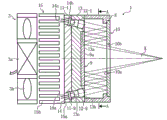
Fig. 1 is the sectional view of the light supply apparatus that relates to of first embodiment of the invention.
Fig. 2 is the sectional view on the A-A line position in Fig. 1.
Fig. 3 is each three-dimensional exploded view partly of light supply apparatus that first embodiment of the invention relates to.
Fig. 4 be the center of curvature axle that shows coupling mirror with each optical axis of light source between partial cross section enlarged drawing under the state that departs from of existence.
Fig. 5 A is that each light source is set to it and penetrates the identical light supply apparatus part schematic diagram of angle between optical axis and the first catoptron.
Fig. 5 B is the light supply apparatus part schematic diagram that the optical axis of the center of curvature axle of coupling mirror and light source is consistent.
Fig. 6 A and Fig. 6 B are the schematic diagram of axial flow fan wind speed profile, and wherein, Fig. 6 A is for showing the side view of wind direction, and Fig. 6 B is for meaning the schematic diagram of air flow region.
Fig. 7 is the schematic diagram that in the light supply apparatus that relates to of embodiment of the present invention, a plurality of light sources are arranged in squares.
Fig. 8 is that in the light supply apparatus that relates to of embodiment of the present invention, a plurality of light sources are the schematic diagram that multi-ring annular is arranged.
In the light supply apparatus that Fig. 9 embodiment of the present invention relates to, the transmissive portions of the first catoptron forms the schematic diagram of the lens shape (convex lens) with curvature.
Figure 10 is the schematic diagram that the transmissive portions of the first catoptron in the light supply apparatus that relates to of embodiment of the present invention forms the lens shape (concave mirror) with curvature.
Figure 11 is the schematic diagram that an example that embodiment of the present invention relates to possesses the image projection device of light supply apparatus.
Figure 12 is the schematic diagram of the light supply apparatus that relates to of another embodiment of the present invention.
Embodiment
The present invention is with the synthetic light of the structure of a plurality of light sources of floor plan, this structure comprises the first reflecting part and the second reflecting part and a plurality of light source that possesses respectively reflecting surface, a plurality of light sources are arranged at around the second reflecting part, the reflecting surface of the reflecting surface of the first reflecting part and the second reflecting part is oppositely arranged, the light of a plurality of light source emissions is incident the second reflecting part after being subject to the first reflecting part reflection, is subject to the second reflecting part reflection.
Below utilize accompanying drawing explanation embodiments of the present invention.Structure same section in each figure is marked by same tag, and omit repeat specification.
Fig. 1 is the sectional view of the light supply apparatus 1 of first embodiment of the invention, and Fig. 2 is the sectional view on the A-A line position in Fig. 1.Fig. 3 is the three-dimensional exploded view of light supply apparatus 1 each part.The light supply apparatus 1 the present invention relates to comprises with lower component: the light source group is configured to a plurality of light source 11-1 to 11-16 and a plurality of coupling mirror 12-1 to 12-16 respectively around the annular floor plan at same center; Light source support 14, for supporting a plurality of light source 11-1 to 11-16; Coupling mirror support 13, for installing a plurality of coupling mirror 12-1 to 12-16; The first catoptron 10 and the second catoptron 9, respectively as the first reflecting part and the second reflecting part, become for making the light penetrated by each coupling mirror 12-1 to 12-16 the light of bringing together that dwindles sectional area to circle ring center's direction; Catoptron support 8; Heat sink 15, for as radiating part; And axial flow fan 3, for as air supplying part.Right side in Fig. 1 is for irradiating side, light supply apparatus 1 from right side roughly according to the order setting of catoptron support 8, coupling mirror support 13, light source support 14, heat sink 15, axial flow fan 3.The first catoptron 10 in present embodiment and the second catoptron 9 are simple catoptron.
Aluminum or heat sink made of copper 15 are installed to be on the side surface 14a that its base portion 15a is close to light source support 14.Stream axle fan 3 is positioned at radiating part 15b mono-side at the base portion 15a back side that is formed on heat sink 15, drive motor 3a in the middle of being arranged on by driving, be positioned at the fan 3b rotation air-supply that periphery forms with blade, blows on radiating part 15b, by air-supply, to radiating part, 15b plays thermolysis.That is to say, in the present embodiment, be arranged on the heat sink 15 on the light source support 14 of supporting a plurality of light sources and make the cooling axial flow fan of heat sink 15 3 form the cooling end that light source is used to heat sink 15 air-supplies.
Light source 11-1 to 11-16 is laser diode, and such as semiconductor Laser device etc., as shown in Figure 1, these light sources insert respectively to be arranged ringwise and runs through fixing in the mounting hole 14c of light source support 14.Light source 11-1 to 11-16 can each self-emission different colours light.The collimating mirror that coupling mirror 12-1 to 12-16 comprises laser diode and the light of this laser diode emission is converted to directional light or brings light together.
Coupling mirror 12-1 to 12-16 is the convex lens formed with glass or plastics, as shown in Figure 4, each coupling mirror 12-1 to 12-16 is set in the through hole 13c formed on coupling mirror support 13, make the center of curvature axle L of each coupling mirror setover to circumferencial direction is inboard with respect to the optical axis L 1 of each light source 11-1 to 11-16, produce center shift amount d between center of curvature axle L and optical axis L 1.Fig. 1 has only shown the relation between coupling mirror 12-1,12-9 and light source 11-1,11-9 typically.
Coupling mirror 12-1 to 12-16 can also be as shown in Fig. 5 A and Fig. 5 B with the relation that arranges of light source 11-1 to 11-16.The state that light source 11-1 to 11-16 and coupling mirror 12-1 to 12-16 are consistent with the center of curvature axle L of each coupling mirror respectively with the optical axis L 1 of each light source with respect to the first catoptron 10 be obliquely installed into, form angle between the ejaculation optical axis penetrated from coupling mirror 12-1 to 12-16 and the first catoptron 10.It is that representative describes that Fig. 5 B closes with arranging between coupling mirror 12-1 and light source 11-1.That is to say, the ejaculation optical axis that the light source group can also be set to each light source is identical with respect to the angle of inclination of the first catoptron 10.
The setting of above-mentioned light source 11-1 to 11-16 and coupling mirror 12-1 to 12-16, as shown in Figure 1, can make from light source 11-1 to 11-16 emission respectively penetrate light respectively by corresponding coupling mirror 12-1 to 12-16, become with respect to the first catoptron 10, to circle ring center's direction, tilt slightly be conical ejaculation light.
In the form shown in Fig. 5 A and Fig. 5 B, a plurality of light source 11-1 to 11-16 and coupling mirror 12-1 to 12-16 are set to, ejaculation optical axis separately is identical with respect to the angle of inclination of the first catoptron 10, now do not need condenser just the light of each self-emission of light source 11-1 to 11-16 can be converged to a place, contribute to reduce element.
Catoptron support 8, coupling mirror support 13 and light source support 14, both can be integrally formed with such as formation such as the metals such as aluminium or resin moulds, also can form individually rear bonding.
The another side 14b of light source support 14 is installed on the installed surface 13d of coupling mirror support 13.In coupling mirror support 13, the core of the face 13b of a side contrary to installed surface 13d forms recess 13a.
On a side surface of the glass sheet of parallel flat, for example the AM aluminum metallization film, form reflecting surface 10a, as the reflecting part of the first catoptron 10.The center section of the first catoptron 10 be 10b,Gai opening portion, opening portion 10b as transmissive portions, form opening at plate thickness direction, can allow light pass through.Transmissive portions can also not form opening portion 10b, but retain and be equivalent to 10bDe position, opening portion while on glass surface, carrying out the aluminium film vapor deposition, evaporation on this position not, in other words, form the aluminum annular-shaped film with evaporation, the part that will be equivalent to opening portion 10b forms transparent part.Perhaps at this position, do not establish transparent plate in order to as transmissive portions, be configured to " by " structure.
It is upper that the second catoptron 9 is arranged on face 13b relative with reflecting surface 13a in coupling mirror support 13, on a side surface of the glass sheet of parallel flat, for example carries out the aluminium film vapor deposition, forms reflecting surface 9a, as the reflecting part of the second catoptron 9.In other words, as shown in Figure 2, the second catoptron 9 is arranged on the central part of the annulus of coupling mirror 12-1 to 12-16, in the recess 13a of coupling mirror support 13.
The light that respectively penetrates by coupling mirror 12-1 to 12-16 is subject to the first catoptron 10 reflections, to coupling mirror 12-1 to 12-16 one side, return, again reflected being positioned at annulus inner central section that coupling mirror 12-1 to 12-16 forms and dividing on second catoptron 9 of (recess 13a), shot to the first catoptron 10 1 sides.Like this, between the first catoptron 10 and the second catoptron 9, after the several interreflection, the zone that sees through that the central part by the first catoptron 10 forms is that opening portion 10b penetrates.
Like this, the light that respectively penetrates penetrated from coupling mirror 12-1 to 12-16 repeatedly reflects through several between the first catoptron 10 and the second catoptron 9, synthetic from coupling mirror 12-1 to 12-16, penetrate respectively penetrate light, reduced cross-sectional area becomes the light beam K brought together simultaneously, the density of this light beam K is improved, becomes high brilliance light beam K and penetrate.
During the first catoptron 10 that each light oblique incidence of penetrating from light source 11-1 to 11-16 forms with the glass plate of mirror material, because reflex moves closer to the center section of the first catoptron 10, for this reason, shorter being convenient to of distance synthesized.And then, can use the glass plate of undressed mirror material, the processing charges that the opening portion that allows light pass through in order to saving is 10 ones.
In the present embodiment, the light order of reflection between the first catoptron 10 and the second catoptron 9 is shown as twice, but the present invention is not limited to this, can set as required suitable order of reflection.
In the present embodiment, can also form light source in conjunction with laser diode and collimating mirror, collimating mirror converts directional light to for the ejaculation light that this laser diode is penetrated.In this case, can save condenser, and will converge to from the ejaculation light of light source 11-1 to 11-16 a position, contribute to reduce part.
Fig. 6 A and Fig. 6 B are the schematic diagram of the wind speed profile of axial flow fan 3.Arrow in Fig. 6 A means wind direction, and the mark B in Fig. 6 B means the inner actual circulation of air zone of axial flow fan 3.
According to Fig. 6, the wind speed profile that axial flow fan is discharged is that the outside is fast inner slow, and wind direction is rotational flow laterally.Each light source 11-1 to 11-16 arranges ringwise in the first embodiment, and is arranged on light source support 14, is positioned at the regional B shown in Fig. 6 B.For this reason, can establish greatlyr by space between light sources, interfere with the heat suppressed between light source, simultaneously, axial flow fan directly and be effectively dried, and improves heat dispersion.And light source 11-1 to 11-16 is fixedly installed on same light source support 14, not only is convenient to the setting of heat sink 15, and contribute to flowing of axial flow fan air-supply.And then, due to the size of light source support 14 and arrange that the circle diameter of a plurality of light source 11-1 to 11-16 can free setting, thereby not only can arbitrarily set quantity of light source but also can use the support that thermal capacity is large, further improve heat dispersion.For this reason, according to above-mentioned the first embodiment, can further improve the thermal diffusivity of miniature light sources device and dwindle the sectional area of the light of a plurality of bright spots (light source) emissions.In addition, the light supply apparatus 1 that above-mentioned the first embodiment relates to not only has above-mentioned various effect, and design freedom is large, can tackle various requirement.The light supply apparatus 1 that this first embodiment relates to can be used for such as image projection devices such as projectors.
Other embodiments below are described.
Fig. 7 is that routine a plurality of light source 11-1 to 11-16 and a plurality of coupling mirror 12-1 to 12-16 are the light supply apparatus 1 that arranged in squares forms, and Fig. 8 is that a plurality of light source 11-1 to 11-32 and a plurality of coupling mirror 12-1 to 12-32 arrange the light supply apparatus 1 formed with two concentric circless (multi-ring annular).As shown in Figure 7, in light supply apparatus 1, each light source 11-1 to 11-16 and coupling mirror 12-1 to 12-16 are arranged in periphery but arrange that shape is not restricted, thereby, be convenient to obtain by the Multi reflection between the first catoptron 10 and the second catoptron 9 light of bringing together that area of section reduces.
And then, as shown in Figure 8, each light source 11-1 to 11-32 and each coupling mirror 12-1 to 12-32 are made to the multi-turn arranged in concentric circles, will further be convenient to increase light quantity.In form shown in Fig. 8, light source 11-1 to 11-32 and each coupling mirror 12-1 to 12-32 are arranged to the annular that two circles have same center, but the layout of annular is not limited to two circles, if need large light quantity, also can arrange three circles, four circle concentric circless.
Fig. 9 and Figure 10 form the transmissive portions of the first catoptron 10 embodiment of the lens shape with curvature.Wherein Fig. 9 illustrated embodiment is installed convex lens 7 as transmissive portions on the 10b of opening portion, and Figure 10 illustrated embodiment is installed concave mirror 6 as transmissive portions on the 10b of opening portion.
Utilize structure shown in Fig. 9, can reduce order of reflection between the first catoptron 10 and the second catoptron 9 to shorten focusing distance, not only can reduce the light loss on the first catoptron 10 and the second catoptron 9, and can make light supply apparatus 1 miniaturization more.
Utilize structure shown in Figure 10, can further reduce the following light quantity homogenizing of incident parts is the incident angle of equal polished rod 16, the homogenizing light quantity.
In the explanation of above-mentioned embodiment, between the first catoptron 10 and the second catoptron 9, be Multi reflection, but also only primary event as shown in figure 12 of order of reflection.With Multi reflection, compare, the light loss that primary event occurs on the first catoptron 10 and the second catoptron 9 is few, thereby preferred this mode.
In addition, the first reflecting part and the second reflecting part also are not limited to the simple catoptron as above-mentioned the first catoptron 10 and the second catoptron 9 employings, can also be with a plurality of mirrors in conjunction with formation.
Figure 11 is an illustration intention that adopts the image projection device 2 of the light supply apparatus 1 the present invention relates to.
Image projection device 2 has with lower component: light supply apparatus 1, the first catoptron 10 and the second catoptron 9, light source support 14, coupling mirror support 13, catoptron support 8, heat sink 15 and the axial flow fan 3 that comprising a plurality of light source 11-1 to 11-16, a plurality of coupling mirror 12-1 to 12-16, core, are light transmission department; Equal polished rod 16 as light quantity homogenizing parts; Relay lens 17, for being sent to image forming surface plate 18 by the ejaculation light after equal polished rod 16 homogenizing; And image projection mirror 19, form for amplifying also transmission image the image formed on panel 18.
The light of each light source 11-1 to 11-16 emission penetrates from light supply apparatus 1 after assembling, and becomes light beam K.The equal polished rod 16 of this light beam K incident, this equal polished rod 16 is known light quantity homogenizing parts, the light quantity of launching for each light source of homogenizing light supply apparatus 1, and the light beam K of the equal polished rod 16 of incident is all passing through total reflection repeatedly in polished rod 16, carry out look and synthesize and the light quantity homogenizing, then penetrate from equal polished rod 16.
The light penetrated from equal polished rod 16 shines image forming surface plate 18 through relay lens 17, then by projection lens 19, is projected on not shown external screen.Image forming surface plate 18 in the image projection device 2 that present embodiment relates to is that an example forms the porjection type panel of image according to modulation signal, in addition, can also use the panel of reflection-type panel or micromirror element (DMD) type.In addition, all polished rod 16 is only routine light quantity homogenizing parts, can also use other known light quantity homogenizing parts in addition.Relay lens 17 is only the typical example that the illumination light that the present invention relates to transmits optical system, the typical example that projection lens 19 is the projection optical system that the present invention relates to.
Like this, by light supply apparatus 1 for image projection device 2, not only can obtain the high density light beam K less with the photosynthetic sectional area of the ejaculation of a plurality of light sources, and, can reduce the incident angle of the equal polished rod 16 of incident, suppress the illumination light diffusion of image forming surface plate 18, can use the projection lens 19 of NA value little (the F value is large), be convenient to manufacturing and designing of projection lens 19, contribute to guarantee image property.In other words, improved heat dispersion and the light quantity homo-effect in the image projection device 2 that uses a plurality of light sources.
In above-mentioned light supply apparatus 1, the light of the first catoptron 10 and the second catoptron 9 reflections penetrates from the core of the first catoptron 10, be converged to light beam K, but the present invention is not so limited, the ejaculation position of light beam K is not limited to as the opening portion 10b of transmissive portions the core of being located at the first catoptron 10, the position of the second catoptron 9 also is not limited to the core that is positioned at coupling mirror support 13, can be according to penetrating direction, penetrating angle, this position of appropriate change.
One illustration intention of the display device of the light supply apparatus 1 that can also the present invention relates to as employing in Figure 11.Display device has with lower component: light supply apparatus 1, the first catoptron 10 and the second catoptron 9, light source support 14, coupling mirror support 13, catoptron support 8, heat sink 15 and the axial flow fan 3 that comprising a plurality of light source 11-1 to 11-16, a plurality of coupling mirror 12-1 to 12-16, core, are light transmission department; Equal polished rod 16 as light quantity homogenizing parts; Relay lens 17, for being sent to image forming surface plate 18 by the ejaculation light after equal polished rod 16 homogenizing; And image forming surface plate 18, form image for the light by light supply apparatus 1 emission.
Claims (12)
1. a light supply apparatus, is characterized in that,
Comprise the first reflecting part and the second reflecting part and a plurality of light source that there is respectively reflecting surface,
Described a plurality of light source is around described the second reflecting part setting,
The reflecting surface of the reflecting surface of described the first reflecting part and described the second reflecting part is oppositely arranged,
The light of described a plurality of light source emissions is subject to rear described the second reflecting part of incident of described the first reflecting part reflection, is subject to the second reflecting part reflection.
2. light supply apparatus according to claim 1, is characterized in that,
Described a plurality of light source is annular or polygon is arranged,
Described the first reflecting part is arranged on the ejaculation direction of light of described a plurality of light source emission, comprising the catoptron section and the unreflecting transmissive portions that there is described reflecting surface and reflect to described light source direction in order to the light will described a plurality of light sources penetrated,
Described the second reflecting part is positioned at described light source one side, and is oppositely arranged with described the first reflecting part, the catoptron section reflection for the light by described a plurality of light source emissions to described the first reflecting part,
The light of described a plurality of light source emissions after the light reflection, penetrates from described transmissive portions as light beam between described the first reflecting part and described the second reflecting part.
3. light supply apparatus according to claim 2, is characterized in that, forms the transmissive portions of described the first reflecting part with the parallel flat of light transmissive.
4. light supply apparatus according to claim 2, is characterized in that, the transmissive portions of described the first reflecting part is formed the lens shape with curvature.
5. according to the described light supply apparatus of any one in claim 1~4, it is characterized in that, it is identical with respect to the angle of inclination of described the first catoptron that described a plurality of light sources are set to the plurality of light source ejaculation optical axis separately.
6. according to the described light supply apparatus of any one in claim 1~5, it is characterized in that, described a plurality of light sources are respectively by forming in conjunction with laser diode and collimating mirror, and this collimating mirror is for being converted to directional light or converging light by the ejaculation light of this laser diode.
7. light supply apparatus according to claim 6, is characterized in that, described a plurality of light sources are set to, and the center of curvature axle of the described collimating mirror in each light source departs from the optical axis of described laser diode, to setovering to the inside in week.
8. according to the described light supply apparatus of any one in claim 1~7, it is characterized in that, described a plurality of light sources are set to have the multi-turn annular layout at same center.
9. according to the described light supply apparatus of any one in claim 1~8, it is characterized in that, further possess radiating part and air supplying part, this radiating part is installed on the holding components of described a plurality of light sources, the cooling described radiating part of this air supplying part air-supply.
10. light supply apparatus according to claim 9, is characterized in that, in described a plurality of light sources, at least a portion light source is positioned on the air flow region of described air supplying part.
11. an image projection device, comprising:
The described light supply apparatus of any one in claim 1~10;
Light quantity homogenizing parts, for the light quantity of each light source of the described light supply apparatus of homogenizing;
Illumination light transmits optical system, for the ejaculation light after described light quantity homogenizing parts homogenizing is sent on the image forming surface plate and forms image; And,
Projection optical system, for the described image formed on amplification the described image forming surface plate of projection.
12. a display device, comprising:
The described light supply apparatus of any one in claim 1~10;
Light quantity homogenizing parts, for the light quantity of each light source of the described light supply apparatus of homogenizing;
The image forming surface plate, form image for the light by described light supply apparatus emission; And,
Illumination light transmits optical system, for the ejaculation light after described light quantity homogenizing parts homogenizing is sent to described image forming surface plate.
Applications Claiming Priority (4)
| Application Number | Priority Date | Filing Date | Title |
|---|---|---|---|
| JP2012-114923 | 2012-05-18 | ||
| JP2012114923 | 2012-05-18 | ||
| JP2013-048137 | 2013-03-11 | ||
| JP2013048137 | 2013-03-11 |
Publications (1)
| Publication Number | Publication Date |
|---|---|
| CN103424973A true CN103424973A (en) | 2013-12-04 |
Family
ID=48468130
Family Applications (1)
| Application Number | Title | Priority Date | Filing Date |
|---|---|---|---|
| CN2013101701682A Pending CN103424973A (en) | 2012-05-18 | 2013-05-10 | Light source apparatus and image projection apparatus and display apparatus |
Country Status (4)
| Country | Link |
|---|---|
| US (1) | US20130308104A1 (en) |
| EP (1) | EP2664958B1 (en) |
| JP (1) | JP6260107B2 (en) |
| CN (1) | CN103424973A (en) |
Cited By (5)
| Publication number | Priority date | Publication date | Assignee | Title |
|---|---|---|---|---|
| CN107427231A (en) * | 2015-04-09 | 2017-12-01 | 西诺德牙科设备有限公司 | method and measuring system for optical measurement object |
| CN107861322A (en) * | 2016-09-22 | 2018-03-30 | 上海激亮光电科技有限公司 | A kind of efficient laser illumination system |
| CN108885388A (en) * | 2016-04-04 | 2018-11-23 | 索尼公司 | Light supply apparatus and image display device |
| CN110345394A (en) * | 2018-04-04 | 2019-10-18 | 深圳市Tcl高新技术开发有限公司 | A kind of light collecting device |
| CN113885207A (en) * | 2016-09-12 | 2022-01-04 | 麦克赛尔株式会社 | Light source device |
Families Citing this family (25)
| Publication number | Priority date | Publication date | Assignee | Title |
|---|---|---|---|---|
| JP6311219B2 (en) * | 2012-07-26 | 2018-04-18 | 株式会社リコー | Illumination light forming device, illumination light source device, and image display device |
| JP6168387B2 (en) | 2013-02-26 | 2017-07-26 | 株式会社リコー | Light source device and image projection device provided with the same |
| JP6179792B2 (en) | 2013-02-26 | 2017-08-16 | 株式会社リコー | Light source device and image projection device provided with the same |
| JP6236811B2 (en) | 2013-03-14 | 2017-11-29 | 株式会社リコー | Light source unit, illumination device, and image projection device |
| JP6349784B2 (en) * | 2013-03-14 | 2018-07-04 | 株式会社リコー | Light source unit, illumination device, and image projection device |
| TW201439661A (en) * | 2013-04-10 | 2014-10-16 | Delta Electronics Inc | Illumination module and projection device using same |
| JP6233687B2 (en) | 2013-08-12 | 2017-11-22 | 株式会社リコー | Light source device and image projection device provided with the same |
| JP6452027B2 (en) | 2013-10-23 | 2019-01-16 | 株式会社リコー | Light source device and image projection device provided with the same |
| JP6476667B2 (en) | 2013-11-01 | 2019-03-06 | 株式会社リコー | Light source device and projector using the same |
| WO2015122075A1 (en) | 2014-02-17 | 2015-08-20 | 株式会社リコー | Optical irradiation device and image display device equipped with same |
| EP3121649B1 (en) | 2014-03-18 | 2019-12-18 | Ricoh Company, Ltd. | Light source device and image projection device having light source device |
| CN106133598B (en) * | 2014-04-08 | 2018-09-21 | 索尼公司 | Light source and image display |
| JP6547270B2 (en) | 2014-10-10 | 2019-07-24 | 株式会社リコー | Light source device and image projector having the light source device |
| FR3034497B1 (en) * | 2015-04-03 | 2020-02-07 | Xyzed | MONOCHROMATIC LED LIGHT SOURCE |
| JP6206560B2 (en) | 2015-09-28 | 2017-10-04 | 株式会社リコー | system |
| JP6701732B2 (en) * | 2015-12-29 | 2020-05-27 | セイコーエプソン株式会社 | Light source device, lighting device, and projector |
| JP6821990B2 (en) * | 2016-07-26 | 2021-01-27 | セイコーエプソン株式会社 | Lighting equipment and projectors |
| US20180100635A1 (en) * | 2016-10-07 | 2018-04-12 | Christie Digital Systems Usa, Inc. | Apparatus for combining light beams |
| TWI625589B (en) * | 2017-03-27 | 2018-06-01 | 晶睿通訊股份有限公司 | Lamp cup and camera |
| JP7268421B2 (en) | 2019-03-18 | 2023-05-08 | 株式会社リコー | Light source optical system, light source device and image projection device |
| CN111722465A (en) | 2019-03-20 | 2020-09-29 | 株式会社理光 | Light source device, image projection device, and light source optical system |
| KR102385020B1 (en) * | 2020-02-17 | 2022-04-14 | 주식회사 라이다스 | Optical system for lidar system |
| JP6813118B2 (en) * | 2020-05-07 | 2021-01-13 | セイコーエプソン株式会社 | Lighting equipment and projector |
| JP7107351B2 (en) * | 2020-12-17 | 2022-07-27 | セイコーエプソン株式会社 | Lighting system and projector |
| WO2024075209A1 (en) * | 2022-10-05 | 2024-04-11 | シャープNecディスプレイソリューションズ株式会社 | Light source device and projector |
Citations (8)
| Publication number | Priority date | Publication date | Assignee | Title |
|---|---|---|---|---|
| US20020114158A1 (en) * | 2001-02-20 | 2002-08-22 | Prokia Technology Co., Ltd. | Illuminating apparatus using multiple light sources |
| EP1333308A2 (en) * | 2002-02-01 | 2003-08-06 | Samsung Electronics Co., Ltd. | Compact illumination system and projection display device employing the same |
| EP1403695A1 (en) * | 2002-09-24 | 2004-03-31 | Agfa-Gevaert AG | Device for exposure of an original comprising homogenised and superposed multiple point light sources |
| WO2006027621A2 (en) * | 2004-09-11 | 2006-03-16 | Apticol Limited | Light engine for projection application |
| CN1831637A (en) * | 2005-03-08 | 2006-09-13 | 三星电子株式会社 | Cooling apparatus and a projector having the same |
| US20100020538A1 (en) * | 2006-09-15 | 2010-01-28 | Stiftung Alfred-Wegener-Institut Fuer Polar- Und Meeresforschung | Reflector emitter |
| CN201429765Y (en) * | 2009-04-15 | 2010-03-24 | 深圳高迪数码有限公司 | LED radiating structure of LCOS projector |
| US20100118530A1 (en) * | 2006-10-12 | 2010-05-13 | Panasonic Corporation | Light-emitting apparatus |
Family Cites Families (17)
| Publication number | Priority date | Publication date | Assignee | Title |
|---|---|---|---|---|
| US5383168A (en) * | 1993-04-01 | 1995-01-17 | Eastman Kodak Company | Actively athermalized optical head assembly |
| US6351453B1 (en) * | 1998-03-26 | 2002-02-26 | Bell Atlantic Network Services, Inc. | Internet service provider (ISP) finder |
| JP4681098B2 (en) * | 2000-04-18 | 2011-05-11 | 日東光学株式会社 | Video projector |
| JP2004013107A (en) * | 2002-06-11 | 2004-01-15 | Olympus Corp | Illuminating optical element |
| US7226188B2 (en) * | 2004-11-19 | 2007-06-05 | Whiterock Design, Llc | Stage lighting methods and apparatus |
| JP2006251149A (en) * | 2005-03-09 | 2006-09-21 | Fujinon Corp | Illumination device and projection type picture display device |
| JP2008203093A (en) * | 2007-02-20 | 2008-09-04 | Mitsutoyo Corp | Illumination device and image measurement apparatus |
| JP4538674B2 (en) * | 2007-07-26 | 2010-09-08 | 株式会社オプトデザイン | Surface illumination unit, surface illumination light source device, surface illumination device, and development substrate for manufacturing surface illumination unit |
| WO2009082737A1 (en) * | 2007-12-24 | 2009-07-02 | Columbia Insurance Company | System for representing colors including an integrating light capsule |
| DE102008006249B4 (en) * | 2008-01-25 | 2011-04-28 | Lanz, Rüdiger | Motor-driven, head-moving headlight |
| JP5315845B2 (en) * | 2008-08-07 | 2013-10-16 | 株式会社リコー | Illumination device and projection-type image display device |
| JP4711155B2 (en) | 2009-06-30 | 2011-06-29 | カシオ計算機株式会社 | Light source device and projector |
| CN102472897B (en) * | 2009-07-13 | 2014-10-22 | 马丁专业公司 | Color-combining illumination device |
| JP5166580B2 (en) * | 2010-08-06 | 2013-03-21 | ポスコ アイシーティ カンパニー リミテッド | Optical semiconductor lighting device |
| US8858040B2 (en) * | 2010-08-23 | 2014-10-14 | Cooliance, Inc. | Cooling methodology for high brightness light emitting diodes |
| JP5601097B2 (en) * | 2010-09-01 | 2014-10-08 | 株式会社リコー | Irradiation device and projector device |
| US20130077283A1 (en) * | 2011-09-23 | 2013-03-28 | Lin Li | Apparatuses and methods for high-efficiency polarization conversion in a projection light engine |
-
2013
- 2013-04-25 EP EP13165397.4A patent/EP2664958B1/en not_active Not-in-force
- 2013-04-29 US US13/872,490 patent/US20130308104A1/en not_active Abandoned
- 2013-05-10 CN CN2013101701682A patent/CN103424973A/en active Pending
- 2013-05-13 JP JP2013101515A patent/JP6260107B2/en not_active Expired - Fee Related
Patent Citations (8)
| Publication number | Priority date | Publication date | Assignee | Title |
|---|---|---|---|---|
| US20020114158A1 (en) * | 2001-02-20 | 2002-08-22 | Prokia Technology Co., Ltd. | Illuminating apparatus using multiple light sources |
| EP1333308A2 (en) * | 2002-02-01 | 2003-08-06 | Samsung Electronics Co., Ltd. | Compact illumination system and projection display device employing the same |
| EP1403695A1 (en) * | 2002-09-24 | 2004-03-31 | Agfa-Gevaert AG | Device for exposure of an original comprising homogenised and superposed multiple point light sources |
| WO2006027621A2 (en) * | 2004-09-11 | 2006-03-16 | Apticol Limited | Light engine for projection application |
| CN1831637A (en) * | 2005-03-08 | 2006-09-13 | 三星电子株式会社 | Cooling apparatus and a projector having the same |
| US20100020538A1 (en) * | 2006-09-15 | 2010-01-28 | Stiftung Alfred-Wegener-Institut Fuer Polar- Und Meeresforschung | Reflector emitter |
| US20100118530A1 (en) * | 2006-10-12 | 2010-05-13 | Panasonic Corporation | Light-emitting apparatus |
| CN201429765Y (en) * | 2009-04-15 | 2010-03-24 | 深圳高迪数码有限公司 | LED radiating structure of LCOS projector |
Cited By (6)
| Publication number | Priority date | Publication date | Assignee | Title |
|---|---|---|---|---|
| CN107427231A (en) * | 2015-04-09 | 2017-12-01 | 西诺德牙科设备有限公司 | method and measuring system for optical measurement object |
| CN108885388A (en) * | 2016-04-04 | 2018-11-23 | 索尼公司 | Light supply apparatus and image display device |
| CN108885388B (en) * | 2016-04-04 | 2021-10-19 | 索尼公司 | Light source device and image display device |
| CN113885207A (en) * | 2016-09-12 | 2022-01-04 | 麦克赛尔株式会社 | Light source device |
| CN107861322A (en) * | 2016-09-22 | 2018-03-30 | 上海激亮光电科技有限公司 | A kind of efficient laser illumination system |
| CN110345394A (en) * | 2018-04-04 | 2019-10-18 | 深圳市Tcl高新技术开发有限公司 | A kind of light collecting device |
Also Published As
| Publication number | Publication date |
|---|---|
| EP2664958A1 (en) | 2013-11-20 |
| EP2664958B1 (en) | 2015-10-28 |
| JP2014199790A (en) | 2014-10-23 |
| JP6260107B2 (en) | 2018-01-17 |
| US20130308104A1 (en) | 2013-11-21 |
Similar Documents
| Publication | Publication Date | Title |
|---|---|---|
| CN103424973A (en) | Light source apparatus and image projection apparatus and display apparatus | |
| CN104007603B (en) | Light supply apparatus and possess the image projection device of this light supply apparatus | |
| CN102411205B (en) | Light source, light combination device and projector with light source | |
| US7712931B1 (en) | Sweep collimator | |
| CN105911805B (en) | A kind of compact-sized light-source system | |
| EP1024398B1 (en) | Solid state based illumination source for a projection display | |
| JP4861328B2 (en) | Lighting system | |
| JP4823898B2 (en) | Compact light source module and projection type image display apparatus using the same | |
| JP2020502783A (en) | Multi-color micro LED array light source | |
| US11163226B2 (en) | Light source system and projection display apparatus | |
| JP6072805B2 (en) | Highly recyclable solid state light source device | |
| CN105556374A (en) | An optical system for producing uniform illumination | |
| CN101937163A (en) | Light source unit, light source apparatus and projector | |
| JP2009295577A (en) | Light-emitting diode light source module | |
| US9459436B2 (en) | Linear LED optical assembly for emitting collimated light | |
| US10237522B2 (en) | Cooling device, light source unit and projector | |
| US20170003580A1 (en) | Apparatus for High Efficiency Laser Static Phosphor Module | |
| JP2007080565A (en) | Light source device and array light source device | |
| US20080123343A1 (en) | Light source device, image display device, optical element and manufacturing method thereof | |
| CN208222182U (en) | Starry sky projector | |
| CN207750788U (en) | Display device and its back lighting device for having radiator-grid | |
| CN104487883B (en) | Beam apparatus for providing electromagnetic beam | |
| JP7499559B2 (en) | Cooling device, light source device and projection device | |
| CN207689817U (en) | Optical system and projector | |
| CN107664873A (en) | Planar light source device and liquid crystal display device |
Legal Events
| Date | Code | Title | Description |
|---|---|---|---|
| C06 | Publication | ||
| PB01 | Publication | ||
| C10 | Entry into substantive examination | ||
| SE01 | Entry into force of request for substantive examination | ||
| C12 | Rejection of a patent application after its publication | ||
| RJ01 | Rejection of invention patent application after publication |
Application publication date: 20131204 |