CN103401437A - IGBT converter chopping module - Google Patents
IGBT converter chopping module Download PDFInfo
- Publication number
- CN103401437A CN103401437A CN2013103491528A CN201310349152A CN103401437A CN 103401437 A CN103401437 A CN 103401437A CN 2013103491528 A CN2013103491528 A CN 2013103491528A CN 201310349152 A CN201310349152 A CN 201310349152A CN 103401437 A CN103401437 A CN 103401437A
- Authority
- CN
- China
- Prior art keywords
- module
- igbt
- low
- inductance bus
- radiator
- Prior art date
- Legal status (The legal status is an assumption and is not a legal conclusion. Google has not performed a legal analysis and makes no representation as to the accuracy of the status listed.)
- Pending
Links
Images


Landscapes
- Inverter Devices (AREA)
- Dc-Dc Converters (AREA)
Abstract
The invention provides an IGBT (Insulated-Gate Bipolar Transistor) converter chopping module; all components that constitute the module are mounted in the module in a laminated manner to form a drawer-type structure; through the drawer-type structure, the external size of the module is reduced, and the internal compactness of a frequency converter cabinet can be improved; meanwhile, the IGBT converter chopping module provided by the embodiment of the invention is high in integration level; an IGBT element, a radiator, a low-sensitivity busbar, an AC output busbar, an absorption capacitor, an IGBT driving component, a pulse distribution board, a current sensor and the like are integrated inside the module to form a complete converter unit; when the power needs to be expanded, all that is needed is to increase the number of the converter units and connect input and output ends of a plurality of modules in parallel without changing the internal device parameters, device arrangement and external structure of the modules, so that the complete converter unit can realize power expansion easily.
Description
Technical field
The present invention relates to the power electronic equipment technical field, particularly a kind of IGBT current transformer copped wave module.
Background technology
IGBT current transformer copped wave module is the core cell that frequency converter plays the copped wave function.When the voltage on DC bus during higher than the condition of predefined higher limit or the step-down that suits the requirements, the copped wave module will be to the braking circuit conveying capacity, when DC bus-bar voltage drops to when presetting lower limit, the copped wave module will stop to the brake apparatus conveying capacity.
Each performance of IGBT current transformer copped wave module has determined the security performance of frequency converter.But the IGBT current transformer copped wave module of extensive use at present comes with some shortcomings.
One, compact is bad, take up room larger: the modular integrated degree of existing copped wave is low, also have some not have integrated, most of product is the size that provides according to the client and design separately, each functional unit is separately independently put, well functional unit is not integrated together, this has just caused module, and not only volume is excessive, and makes electric property, heat dispersion and structural behaviour all be subject to certain impact.
Two, installation and maintenance inconvenience: many current transformers lack the consideration of modularization, rapidity due to structural design, to installation and maintenance, bring a lot of difficulties, usually in order to change an IGBT converter module, need a lot of bolts of dismounting or other part, like this except workload is large, the reliability of returning system is that bulk life time brings and has a strong impact on.
Three, the Secondary Design workload is large: because converter module is the elementary cell of current transformer, now based on the desired power grade difference of different equipment, existing current transformer need to carry out large-scale structural design, circuit design and heat dissipation design according to different power grades.
Four, power expansion difficulty: be subjected to the semiconductor technology horizontal constraints, if meet more powerful requirement, must carry out the series and parallel use to element, existing IGBT current transformer copped wave module often need to be done very large change on circuit and structure, could meet more jumbo requirement.
Summary of the invention
In view of this, the invention provides a kind of IGBT current transformer copped wave module, to meet modern industry transmission current transformer field, require high, the maintainable high and power expansion of degree of modularity purpose easily.
To achieve these goals, the present invention has adopted following technical scheme:
A kind of IGBT current transformer copped wave module, comprise, base assembly, radiator, IGBT element, low-inductance bus, interchange output busbar, absorption capacitor, IGBT driven unit, pulse distribution plate, current sensor and cap assembly, the stacked installation of each components and parts forms drawer-type structure;
Wherein, described base assembly is positioned at the bottom of described drawer-type structure;
Described radiator is positioned at the top of described base assembly;
Described IGBT element is positioned at the top of described radiator;
Described low-inductance bus exports with described the interchange top that busbar is positioned at described IGBT element, wherein, described low-inductance bus comprises main part and from the outwardly directed extension of described main part, described main part is L shaped, being shaped as of described interchange output busbar is L shaped, the extension of described low-inductance bus is connected with a described end that exchanges the output busbar, and the other end of described interchange output busbar is connected with deceleration loading;
Described current sensor is set on described interchange output busbar;
Described IGBT driven unit and described absorption capacitor are spaced apart in the top of described low-inductance bus, and the lead-out terminal of described absorption capacitor is electrically connected to the positive and negative output of described low-inductance bus;
Described pulse distribution plate and described cap assembly are positioned at the top of described absorption capacitor.
More preferably, described low-inductance bus is complementary staggered relatively in the top of described IGBT element with the described output busbar that exchanges.
More preferably, described low-inductance bus is formed by stacking by copper bar layer and insulating barrier, and peripheral edge seals with insulating material.
More preferably, described module also comprises, is fixed on the epoxy plate on described base assembly, and described IGBT driven unit is fixed on described epoxy plate.
More preferably, described module also comprises, be fixed on described base assembly be used to the first epoxy press strip of supporting described low-inductance bus be used to supporting described the second epoxy press strip that exchanges the output busbar.
More preferably, on described radiator, be provided with temperature relay, when described temperature relay surpasses preset temperature for the temperature when described IGBT current transformer copped wave module, control described IGBT current transformer copped wave module derate operation or shut down.
More preferably, described radiator adopts water cooling method.
More preferably, described IGBT element has 2n, and 2n described IGBT element be evenly distributed on the top of described radiator, wherein, n >=1, n is natural number.
The IGBT current transformer copped wave module of the embodiment of the present invention, by forming stacked being arranged in this module of each components and parts of module, form drawer-type structure.This drawer-type structure has dwindled the overall volume of module, has improved the compactedness in frequency-charger cabinet.Simultaneously, the integrated level of the IGBT current transformer copped wave module that the embodiment of the present invention provides is high, its inside is integrated with the parts such as IGBT element, radiator, low-inductance bus, interchange output busbar, absorption capacitor, IGBT driven unit, pulse distribution plate, current sensor, has formed a complete converter cell.At needs during to power expansion, only need to increase the quantity of this converter cell, the input and output of a plurality of modules are connected in parallel, do not need to change device parameters, device layout and the contour structures of inside modules, so this complete converter cell is easily realized power expansion.
In addition, the design of the versatility of this module and high integration design, can be applicable to varying environment, different loads, different capacity grade.
In addition, this module main circuit connected mode is quick, only needs to adopt copper bar or cable to connect positive and negative busbar and outgoing line busbar, can assemble fast, safeguard.
The accompanying drawing explanation
For the technical scheme in the embodiment of the present invention clearly is described, in below describing embodiment, need the accompanying drawing that uses to do to introduce briefly, apparently, accompanying drawing in the following describes is that more of the present invention everything goes well, for those of ordinary skills, under the prerequisite of not paying creative work, can also obtain according to these accompanying drawings other accompanying drawing.
Fig. 1 is the front view of the IGBT current transformer copped wave module of the embodiment of the present invention;
Fig. 2 is the vertical view of the IGBT current transformer copped wave module of the embodiment of the present invention;
Fig. 3 is the upward view of the IGBT current transformer copped wave module of the embodiment of the present invention;
Fig. 4 is the positive internal structure schematic diagram of the IGBT current transformer copped wave module of the embodiment of the present invention;
Fig. 5 is the end view of the IGBT current transformer copped wave module of the embodiment of the present invention;
Fig. 6 is the decomposing schematic representation of the IGBT current transformer copped wave module of the embodiment of the present invention;
Fig. 7 is the schematic diagram of two IGBT current transformer copped wave modules expansion in parallel;
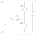
Fig. 8 is the circuit diagram of the IGBT current transformer copped wave module of the embodiment of the present invention.
In figure:
1. base assembly; 2. radiator; 3.IGBT element; 4. low-inductance bus; 5. epoxy plate; 6. high voltage gate drive plate; 7. absorption capacitor; 8. pulse distribution plate; 9. ten three-prong plugs; 10. cap assembly; 11. current sensor; 12. epoxy press strip 1; 13. epoxy press strip 2; 14. temperature relay; 15. exchange the output busbar; 16. copped wave module.
Embodiment
For above-mentioned purpose of the present invention, feature and advantage can be become apparent more, below in conjunction with accompanying drawing, the specific embodiment of the present invention is described in detail.
The embodiment of the present invention provides a kind of IGBT current transformer copped wave module, comprise, base assembly, radiator, IGBT element, low-inductance bus, interchange output busbar, absorption capacitor, IGBT driven unit, pulse distribution plate, current sensor and cap assembly, the stacked installation of each components and parts form drawer-type structure;
Wherein, described base assembly is positioned at the bottom of described drawer-type structure;
Described radiator is positioned at the top of described base assembly; Described IGBT element is positioned at the top of described radiator; Described low-inductance bus exports with described the interchange top that busbar is positioned at described IGBT element, wherein, described low-inductance bus comprises main part and from the outwardly directed extension of described main part, described main part is L shaped, being shaped as of described interchange output busbar is L shaped, the extension of described low-inductance bus is connected with a described end that exchanges the output busbar, and the publish books other end of busbar of described interchange is connected with deceleration loading;
Described current sensor is set on described interchange output busbar;
Described IGBT driven unit and described absorption capacitor are spaced apart in the top of described low-inductance bus, and the lead-out terminal of described absorption capacitor is electrically connected to government's output of described low-inductance bus;
Described pulse distribution plate and described cap assembly are positioned at the top of described absorption capacitor.
The IGBT current transformer copped wave module of the embodiment of the present invention, by forming stacked being arranged in this module of each assembly of module, form drawer-type structure.This drawer-type structure has dwindled the overall volume of module, has improved the compactedness in frequency-charger cabinet.Simultaneously, the IGBT current transformer copped wave inside modules that the embodiment of the present invention provides is integrated with the parts such as IGBT element, radiator, low-inductance bus, interchange output busbar, absorption capacitor, IGBT driven unit, pulse distribution plate, current sensor, has formed a complete converter cell.At needs during to power expansion, only need to increase the quantity of this converter cell, the input and output of a plurality of modules are connected in parallel, do not need to change device parameters, device layout and the contour structures of inside modules, so this complete converter cell is easily realized power expansion.
In addition, the design of the versatility of this module and high integration design, can be applicable to varying environment, different loads, different capacity grade.
In addition, this module main circuit connected mode is quick, only needs to adopt copper bar or cable to connect positive and negative busbar and outgoing line busbar, can assemble fast, safeguard.
View (Fig. 1 to Fig. 3 and Fig. 5) and positive internal structure schematic diagram (Fig. 4) below in conjunction with the different directions of this IGBT current transformer copped wave module are introduced its structure in detail.
For the ease of understanding the spatial relation of this IGBT current transformer copped wave module, regard whole module as a drawer-type structure, its inner all parts is equivalent to the layer structure of this drawer-type structure.
Consult Fig. 1 to Fig. 5, base assembly 1 is positioned at the bottom of IGBT current transformer copped wave module, namely is positioned at the bottom of the drawer-type structure that forms, and is equivalent to drawer box, plays a part whole module is fixed in frequency-charger cabinet.As one embodiment of the present of invention, this base assembly 1 can vertically be fixed in frequency-charger cabinet as Figure 1-5, can certainly laterally be fixed in frequency-charger cabinet.
The IGBT element 3 of 2 special-purpose copped waves is installed on radiator 2, and this IGBT element is equivalent to the second layer structure of drawer-type structure.The effect of this IGBT element 3 is that the number of this IGBT element 3 is even number as the switching device of the chopper circuit of IGBT current transformer copped wave module, and is at least two.In order to take full advantage of radiator 2 heat radiations, this even number IGBT element 3 is evenly arranged in the top of radiator 2.
Low-inductance bus 4 exports with exchanging the top that busbar is positioned at the IGBT element, and this low-inductance bus 4 exports with exchanging the three-decker that busbar 15 is equivalent to drawer-type structure.This low-inductance bus 4 comprises main part and from the outwardly directed extension of described main part, described main part is L shaped shape, and the shape of described interchange output busbar is also L shaped shape.Low-inductance bus 4 with exchange output busbar 15 can be staggered relatively in the top of IGBT element 3 according to complementary mode.The extension of this low-inductance bus 4 is used for connecting the both positive and negative polarity busbar of main circuit on frequency-charger cabinet, and conducts electricity and be connected with IGBT element 3.
This low-inductance bus 4 is overrided to form by copper bar layer and insulating barrier, and peripheral edge seals with insulating material.
The IGBT driven unit be high voltage gate drive plate 6 and absorption capacitor 7 between the upper and lower every the top that is distributed in described low-inductance bus 4, high voltage gate drive plate 6 and absorption capacitor 7 are equivalent to the four-layer structure of module.High voltage gate drive plate 6 is used for driving IGBT element 3, controls turning on and off of IGBT element 3.
This IGBT current transformer copped wave module can also comprise the epoxy plate 5 that is bolted on base assembly 1, and high voltage gate drive plate 6 can be fixed on epoxy plate 5 like this.Due to rigidity and the good insulating of the epoxy material of making epoxy plate 5, epoxy plate 5 plays a part to support high voltage gate drive plate 6 and isolates high pressure on low-inductance bus 4.
This IGBT current transformer copped wave module can also comprise epoxy press strip 13, this epoxy press strip 13 comprises the first epoxy press strip and the second epoxy press strip, this the first epoxy press strip and the second epoxy press strip all are fixed on base assembly 1, the first epoxy press strip works to support low-inductance bus 4, more particularly, the first epoxy press strip supports the both positive and negative polarity part of low-inductance bus 4, and the second epoxy press strip plays a part to support to exchange exports busbar.
Wherein, on cap assembly 10, be fixed with ten three-prong plugs 9, this IGBT current transformer copped wave module is carried out wiring by this ten three-prong plug 9 with the whole cabinet of frequency converter and is connected.
The above is the concrete structure of the IGBT current transformer copped wave module of the embodiment of the present invention.For position and the annexation of the components and parts of more clearly understanding this IGBT current transformer copped wave module, can also consult the decomposing schematic representation of this IGBT current transformer copped wave module, refer to Fig. 6.
The component structure of this IGBT current transformer copped wave module is rationally distributed, and the positive and negative busbar of module main circuit adopts low-inductance bus to connect, and effectively reduces the switch overvoltage, has improved the electric property of whole system.Radiator adopts water cooling method, be conducive to reduce the thermal resistance of radiator, improve the power output of module, can allow the heat dispersion of whole system reach good effect, at one, on temperature spot, reach a poised state preferably, improve the reliability of device and system.
This IGBT current transformer copped wave module adopts drawer-type structure, has greatly reduced the overall dimension of this module, and the size of the general construction of this module for example can be 334x385x199mm, has greatly improved the compactedness in frequency-charger cabinet.
In addition, the integrated level of this IGBT current transformer copped wave module is high, its inner each integrated components and parts have formed a complete converter cell, like this when frequency converter is carried out to power expansion, can only need to increase the quantity of converter module, the input and output parallel connection of a plurality of modules can be realized to the expansion upgrading of power, not need to change device parameters, device component and contour structures of inside modules etc., so the IGBT current transformer copped wave module that the embodiment of the present invention provides easily realizes expansion.Figure 7 shows that the structural representation of two IGBT current transformer copped wave modules expansion in parallel.
The versatility design of this IGBT current transformer copped wave module, high integration design, can be applicable to different environment such as plateau, ocean, sandy beach etc., different loads such as air-conditioning, wind power generation, oil drilling, Ship Propeling etc., different power grades are as from 400KW to 5MW.
This IGBT current transformer copped wave module main circuit connected mode is quick, only needs to adopt copper bar or cable to connect positive and negative busbar and outgoing line busbar, can assemble fast, safeguard, reduces labor cost, improves barrier for some reason and safeguards reliability and the life problems of bringing.
Below in conjunction with circuit diagram Fig. 8 of this IGBT current transformer copped wave module, introduce in detail the circuit theory of this IGBT current transformer copped wave module.
Be understandable that, IGBT current transformer copped wave module shown in Figure 8 comprises IGBT V17 and the V18 of two special-purpose copped waves, current sensor LH12 and absorption capacitor C3.When the voltage on DC bus during higher than the condition of the higher limit of in advance setting or the step-down that suits the requirements, the copped wave module will send control command, which IGBT opens an IGBT(in V17 or V18 specifically opens and depends on the braking circuit wiring, as brake wiring for-UDC and+R, open V17, if connect+UDC and+R opens V18), after IGBT opens, will be to the braking circuit conveying capacity; When DC bus-bar voltage drops to lower than in advance preset lower limit, the copped wave module will send order, turn-off the IGBT that opens, thereby stop to the brake apparatus conveying capacity.Since Absorption Capacitance C3 uses, suppressed the overvoltage of IGBT switch, current sensor is in order to measure when IGBT opens the size of current that flows to braking circuit.
The above is only preferred embodiment of the present invention, not the present invention is done to any pro forma restriction.Although the present invention discloses as above with preferred embodiment, yet not in order to limit the present invention.Any those of ordinary skill in the art, do not breaking away from technical solution of the present invention scope situation, all can utilize method and the technology contents of above-mentioned announcement to make many possible changes and modification to technical solution of the present invention, or be revised as the equivalent embodiment of equivalent variations.Therefore, every content that does not break away from technical solution of the present invention,, all still belong in the scope of technical solution of the present invention protection any simple modification made for any of the above embodiments, equivalent variations and modification according to technical spirit of the present invention.
Claims (8)
1. IGBT current transformer copped wave module, it is characterized in that, comprise, base assembly, radiator, IGBT element, low-inductance bus, interchange output busbar, absorption capacitor, IGBT driven unit, pulse distribution plate, current sensor and cap assembly, the stacked installation of each components and parts forms drawer-type structure;
Wherein, described base assembly is positioned at the bottom of described drawer-type structure;
Described radiator is positioned at the top of described base assembly;
Described IGBT element is positioned at the top of described radiator;
Described low-inductance bus exports with described the interchange top that busbar is positioned at described IGBT element, wherein, described low-inductance bus comprises main part and from the outwardly directed extension of described main part, described main part is L shaped, being shaped as of described interchange output busbar is L shaped, the extension of described low-inductance bus is connected with a described end that exchanges the output busbar, and the other end of described interchange output busbar is connected with deceleration loading;
Described current sensor is set on described interchange output busbar;
Described IGBT driven unit and described absorption capacitor are spaced apart in the top of described low-inductance bus, and the lead-out terminal of described absorption capacitor is electrically connected to the positive and negative output of described low-inductance bus;
Described pulse distribution plate and described cap assembly are positioned at the top of described absorption capacitor.
2. module according to claim 1, is characterized in that, described low-inductance bus is complementary staggered relatively in the top of described IGBT element with the described output busbar that exchanges.
3. module according to claim 1, is characterized in that, described low-inductance bus is formed by stacking by copper bar layer and insulating barrier, and peripheral edge seals with insulating material.
4. the described module of according to claim 1-3 any one, is characterized in that, described module also comprises, is fixed on the epoxy plate on described base assembly, and described IGBT driven unit is fixed on described epoxy plate.
5. module according to claim 4, is characterized in that, described module also comprises, be fixed on described base assembly be used to the first epoxy press strip of supporting described low-inductance bus be used to supporting described the second epoxy press strip that exchanges the output busbar.
6. module according to claim 5; it is characterized in that; on described radiator, be provided with temperature relay, when described temperature relay surpasses preset temperature for the temperature when described IGBT current transformer copped wave module, control described IGBT current transformer copped wave module derate operation or shut down.
7. the described module of according to claim 1-3 any one, is characterized in that, described radiator adopts water cooling method.
8. the described module of according to claim 1-3 any one, is characterized in that, described IGBT element has 2n, and 2n described IGBT element be evenly distributed on the top of described radiator, wherein, n >=1, n is natural number.
Priority Applications (1)
| Application Number | Priority Date | Filing Date | Title |
|---|---|---|---|
| CN2013103491528A CN103401437A (en) | 2013-08-12 | 2013-08-12 | IGBT converter chopping module |
Applications Claiming Priority (1)
| Application Number | Priority Date | Filing Date | Title |
|---|---|---|---|
| CN2013103491528A CN103401437A (en) | 2013-08-12 | 2013-08-12 | IGBT converter chopping module |
Publications (1)
| Publication Number | Publication Date |
|---|---|
| CN103401437A true CN103401437A (en) | 2013-11-20 |
Family
ID=49565006
Family Applications (1)
| Application Number | Title | Priority Date | Filing Date |
|---|---|---|---|
| CN2013103491528A Pending CN103401437A (en) | 2013-08-12 | 2013-08-12 | IGBT converter chopping module |
Country Status (1)
| Country | Link |
|---|---|
| CN (1) | CN103401437A (en) |
Cited By (5)
| Publication number | Priority date | Publication date | Assignee | Title |
|---|---|---|---|---|
| CN106357126A (en) * | 2016-10-31 | 2017-01-25 | 天津安捷励电控技术有限责任公司 | Current control structure, motor controller and electric vehicle |
| CN106564405A (en) * | 2016-10-19 | 2017-04-19 | 株洲中车时代电气股份有限公司 | Drive controller of new energy vehicle |
| CN108123599A (en) * | 2016-11-29 | 2018-06-05 | 中车株洲电力机车研究所有限公司 | A kind of current transformer copped wave module |
| CN110098718A (en) * | 2018-01-30 | 2019-08-06 | 中车株洲电力机车研究所有限公司 | A kind of current transformator power module |
| CN112152599A (en) * | 2020-08-13 | 2020-12-29 | 中车株洲电力机车研究所有限公司 | All-solid-state direct current circuit breaker |
Citations (10)
| Publication number | Priority date | Publication date | Assignee | Title |
|---|---|---|---|---|
| CN1546340A (en) * | 2003-12-05 | 2004-11-17 | 株洲时代集团公司 | A universalized, integrated and modularized IGBT traction converter module |
| CN101197530A (en) * | 2007-12-13 | 2008-06-11 | 西南交通大学 | Suspending chopper box of magnetic suspension train |
| CN101222173A (en) * | 2008-01-02 | 2008-07-16 | 株洲南车时代电气股份有限公司 | High pressure IGBT current transformer module |
| CN101404445A (en) * | 2008-11-12 | 2009-04-08 | 中国北车股份有限公司大连电力牵引研发中心 | Current transformer power module main body apparatus and its processing method |
| CN101902119A (en) * | 2010-06-13 | 2010-12-01 | 中国北车股份有限公司大连电力牵引研发中心 | Brake power device and brake wave chopper |
| JP2012110152A (en) * | 2010-11-18 | 2012-06-07 | Nabtesco Corp | Converter |
| CN102624205A (en) * | 2012-04-16 | 2012-08-01 | 株洲南车时代电气股份有限公司 | Power module of converter |
| CN102801285A (en) * | 2012-08-15 | 2012-11-28 | 株洲南车时代电气股份有限公司 | High-voltage IGBT converter module |
| CN103078471A (en) * | 2011-10-26 | 2013-05-01 | 中国北车股份有限公司大连电力牵引研发中心 | Power module and current converter |
| CN202931226U (en) * | 2012-10-16 | 2013-05-08 | 南车株洲电力机车研究所有限公司 | IGBT current transformer module |
-
2013
- 2013-08-12 CN CN2013103491528A patent/CN103401437A/en active Pending
Patent Citations (10)
| Publication number | Priority date | Publication date | Assignee | Title |
|---|---|---|---|---|
| CN1546340A (en) * | 2003-12-05 | 2004-11-17 | 株洲时代集团公司 | A universalized, integrated and modularized IGBT traction converter module |
| CN101197530A (en) * | 2007-12-13 | 2008-06-11 | 西南交通大学 | Suspending chopper box of magnetic suspension train |
| CN101222173A (en) * | 2008-01-02 | 2008-07-16 | 株洲南车时代电气股份有限公司 | High pressure IGBT current transformer module |
| CN101404445A (en) * | 2008-11-12 | 2009-04-08 | 中国北车股份有限公司大连电力牵引研发中心 | Current transformer power module main body apparatus and its processing method |
| CN101902119A (en) * | 2010-06-13 | 2010-12-01 | 中国北车股份有限公司大连电力牵引研发中心 | Brake power device and brake wave chopper |
| JP2012110152A (en) * | 2010-11-18 | 2012-06-07 | Nabtesco Corp | Converter |
| CN103078471A (en) * | 2011-10-26 | 2013-05-01 | 中国北车股份有限公司大连电力牵引研发中心 | Power module and current converter |
| CN102624205A (en) * | 2012-04-16 | 2012-08-01 | 株洲南车时代电气股份有限公司 | Power module of converter |
| CN102801285A (en) * | 2012-08-15 | 2012-11-28 | 株洲南车时代电气股份有限公司 | High-voltage IGBT converter module |
| CN202931226U (en) * | 2012-10-16 | 2013-05-08 | 南车株洲电力机车研究所有限公司 | IGBT current transformer module |
Cited By (7)
| Publication number | Priority date | Publication date | Assignee | Title |
|---|---|---|---|---|
| CN106564405A (en) * | 2016-10-19 | 2017-04-19 | 株洲中车时代电气股份有限公司 | Drive controller of new energy vehicle |
| CN106564405B (en) * | 2016-10-19 | 2019-04-19 | 株洲中车时代电气股份有限公司 | A kind of new-energy automobile drive control device |
| CN106357126A (en) * | 2016-10-31 | 2017-01-25 | 天津安捷励电控技术有限责任公司 | Current control structure, motor controller and electric vehicle |
| CN108123599A (en) * | 2016-11-29 | 2018-06-05 | 中车株洲电力机车研究所有限公司 | A kind of current transformer copped wave module |
| CN108123599B (en) * | 2016-11-29 | 2020-05-12 | 中车株洲电力机车研究所有限公司 | Chopping module of converter |
| CN110098718A (en) * | 2018-01-30 | 2019-08-06 | 中车株洲电力机车研究所有限公司 | A kind of current transformator power module |
| CN112152599A (en) * | 2020-08-13 | 2020-12-29 | 中车株洲电力机车研究所有限公司 | All-solid-state direct current circuit breaker |
Similar Documents
| Publication | Publication Date | Title |
|---|---|---|
| CN101741227B (en) | Water-cooled three-phase diode-clamped three-level inverted power module | |
| CN201616760U (en) | Water-cooled power module of three-phase diode-clamped three-level inverter | |
| CN103138184B (en) | locomotive converter cabinet | |
| CN102136730B (en) | Movable-type static synchronous compensator with compact structure design | |
| CN201418024Y (en) | Half-bridge power module and back to back type current transformer constituted by the half-bridge power module | |
| CN104201867B (en) | Three-level IGBT power cabinet based on heat pipe radiator | |
| CN103401437A (en) | IGBT converter chopping module | |
| CN106026693A (en) | High-integration converter module | |
| CN204030990U (en) | Lamination spraying row mixes the new power converter unit using with composite bus bar | |
| CN104167933A (en) | Novel power conversion unit allowing laminated coating row and composite busbar to be used in hybrid mode | |
| CN101447740A (en) | High-voltage converter current transforming unit with modularized space structure | |
| CN202997950U (en) | Single-phase bridge type inverter based on water cooling | |
| CN201726303U (en) | High-power high-voltage inverter power unit | |
| CN204257409U (en) | The capacitance component of frequency converter and frequency converter | |
| CN202309481U (en) | Tri-level middling voltage converter power module | |
| CN208806749U (en) | A kind of converter module | |
| CN103354231A (en) | IGBT power unit and sub-module for VSC-HVDC (voltage source converter high voltage direct current) | |
| CN202395663U (en) | Super-high-capacity single-phase bridge-type inverter adopting water-cooling heat radiating | |
| CN110932565A (en) | Current transformer for passenger-cargo dual-purpose locomotive | |
| CN204334378U (en) | A kind of inverter module | |
| CN204258594U (en) | The isolation rubber cushion blocks of IGBT pipe binding post and frequency converter | |
| CN203313041U (en) | Flexible direct-current power transmission power module | |
| CN204334294U (en) | Frequency converter | |
| CN203813676U (en) | IGBT power unit | |
| CN102170220A (en) | Component connection structure of voltage source converter based on full-control device |
Legal Events
| Date | Code | Title | Description |
|---|---|---|---|
| C06 | Publication | ||
| PB01 | Publication | ||
| C10 | Entry into substantive examination | ||
| SE01 | Entry into force of request for substantive examination | ||
| RJ01 | Rejection of invention patent application after publication |
Application publication date: 20131120 |
|
| RJ01 | Rejection of invention patent application after publication |