CN103394514A - Quick dismantling and replacing device for bearing pedestals of working roll - Google Patents
Quick dismantling and replacing device for bearing pedestals of working roll Download PDFInfo
- Publication number
- CN103394514A CN103394514A CN2013103568214A CN201310356821A CN103394514A CN 103394514 A CN103394514 A CN 103394514A CN 2013103568214 A CN2013103568214 A CN 2013103568214A CN 201310356821 A CN201310356821 A CN 201310356821A CN 103394514 A CN103394514 A CN 103394514A
- Authority
- CN
- China
- Prior art keywords
- roll
- replacing device
- tracks
- working roll
- quick dismantling
- Prior art date
- Legal status (The legal status is an assumption and is not a legal conclusion. Google has not performed a legal analysis and makes no representation as to the accuracy of the status listed.)
- Pending
Links
Images

Abstract
The invention relates to the technical field of cold rolled production auxiliary equipment, and provides a quick dismantling and replacing device for bearing pedestals of a working roll. The quick dismantling and replacing device comprises a roll replacing rack, two hydraulic trolleys, four tracks arranged in parallel, and a roll storage rack, wherein each hydraulic trolley is arranged on two tracks, and the roll replacing rack and the roll storage rack are fixedly arranged in the middle of the tracks. The quick dismantling and replacing device has the advantages and the positive effects as follows: due to adoption of the technical scheme, eight working rolls can be replaced by two workers per hour, the production efficiency can be improved by 50%, the labor intensity of workers is greatly reduced, and the number of required overhead traveling cranes is reduced; the quick dismantling and replacing device is simple in structure, convenient to maintain and low in machining cost.
Description
Technical field
The invention belongs to cold rolling production auxiliary equipment technical field, especially relate to a kind of working roll bearing block fast dismantling changing device.
Background technology
The working roll two ends of cold-rolling mill are arranged on two bearing blocks, rotate under the driving of transmission device, complete the rolling function to sheet material.Working roll need to check to bearing block to also have after moving a period of time, working roll after completing the plate rolling of some,, because of the working roll that roll surface wearing need to more renew, all needs to face the dismounting problem of bearing block.
In existing technology, cold rolling factory changes program to bearing seat of operation roll of mill: utilize a day handlebar working roll to winch on roll-changing platform, coordinate again single dismounting bearing block with the people with overhead traveling crane, winch to by the new roller of bearing block to be installed with a day handlebar bearing block after having torn open, the people coordinates single the bearing block new roller of packing into overhead traveling crane again.The length consuming time of above-mentioned working procedure, production efficiency is low, and personnel labor intensity is large.
Summary of the invention
The problem to be solved in the present invention is to provide a kind of working roll bearing block fast dismantling changing device of realizing fast roll changing.
For solving the problems of the technologies described above, the technical solution used in the present invention is:
Working roll bearing block fast dismantling changing device, comprise roll change stand, two hydraulic trolley, four tracks that be arranged in parallel and store up the roller stand, each described hydraulic trolley is placed on respectively on two tracks, at central authorities' difference fixed placement roll change stand and the storage roller stand of track.
Preferably, described hydraulic trolley comprises the hydraulic cylinder between vehicle frame, supporting plate and vehicle frame and supporting plate, described bottom of frame fixed installation pulley.
Advantage and good effect that the present invention has are: owing to adopting technique scheme, said apparatus two people per hour can change eight working rolls, can enhance productivity 50%, and worker's labour intensity reduces greatly, and can reduce the overhead traveling crane consumption; The tool apparatus structure is simple, and is easy to maintenance, and processing cost is low.
Description of drawings
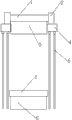
Fig. 1 is structural representation of the present invention;
Fig. 2 is the structural representation of hydraulic trolley of the present invention.
In figure:
1, working roll 2, bearing block 3, roll change stand
4, hydraulic trolley 5, track 6, storage roller stand
7, vehicle frame 8, supporting plate 9, hydraulic cylinder
10, pulley
The specific embodiment
As shown in Figure 1, working roll bearing block fast dismantling changing device of the present invention, comprise roll change stand 3, two hydraulic trolley 4, four tracks that be arranged in parallel 5 and store up roller stand 6, each described hydraulic trolley 4 is placed on two tracks, at central authorities' difference fixed placement roll change stand 3 and the storage roller stand 6 of track.
As shown in Figure 2, described hydraulic trolley 4 comprises the hydraulic cylinder 9 between vehicle frame 7, supporting plate 8 and vehicle frame 7 and supporting plate 8, described vehicle frame 7 bottom fixed installation pulleys 10.
The course of work of this example: the working roll to be changed 1 that utilizes day handlebar to contain bearing block 2 is placed on roll change stand 3, then simultaneously two bearing blocks 2 are lifted to height for convenience detach by two hydraulic trolley 4, the bearing block 2 at quick-detachment working roll 1 two ends, the pulley 10 of hydraulic trolley 4 is along track 5 walkings, the bearing block 2 that transportation disassembles is to the storage roller stand 6 of placing new working roll 1, utilize the liftable function of hydraulic trolley 4, fast bearing block 2 is mounted on new working roll 1.
Above one embodiment of the present of invention are had been described in detail, but described content is only preferred embodiment of the present invention, can not be considered to be used to limiting practical range of the present invention.All equalizations of doing according to the present patent application scope change and improve etc., within all should still belonging to patent covering scope of the present invention.
Claims (2)
1. working roll bearing block fast dismantling changing device, it is characterized in that: comprise roll change stand, two hydraulic trolley, four tracks that be arranged in parallel and store up the roller stand, each described hydraulic trolley is placed on respectively on two tracks, at central authorities' difference fixed placement roll change stand and the storage roller stand of track.
2. working roll bearing block fast dismantling changing device according to claim 1, it is characterized in that: described hydraulic trolley comprises the hydraulic cylinder between vehicle frame, supporting plate and vehicle frame and supporting plate, described bottom of frame fixed installation pulley.
Priority Applications (1)
| Application Number | Priority Date | Filing Date | Title |
|---|---|---|---|
| CN2013103568214A CN103394514A (en) | 2013-08-15 | 2013-08-15 | Quick dismantling and replacing device for bearing pedestals of working roll |
Applications Claiming Priority (1)
| Application Number | Priority Date | Filing Date | Title |
|---|---|---|---|
| CN2013103568214A CN103394514A (en) | 2013-08-15 | 2013-08-15 | Quick dismantling and replacing device for bearing pedestals of working roll |
Publications (1)
| Publication Number | Publication Date |
|---|---|
| CN103394514A true CN103394514A (en) | 2013-11-20 |
Family
ID=49558341
Family Applications (1)
| Application Number | Title | Priority Date | Filing Date |
|---|---|---|---|
| CN2013103568214A Pending CN103394514A (en) | 2013-08-15 | 2013-08-15 | Quick dismantling and replacing device for bearing pedestals of working roll |
Country Status (1)
| Country | Link |
|---|---|
| CN (1) | CN103394514A (en) |
Cited By (2)
| Publication number | Priority date | Publication date | Assignee | Title |
|---|---|---|---|---|
| CN104891323A (en) * | 2015-05-13 | 2015-09-09 | 莱芜钢铁集团有限公司 | Device and method for rapid replacement of lower connecting shaft of horizontal rolling mill |
| CN110449468A (en) * | 2019-07-22 | 2019-11-15 | 昆山铝业有限公司 | A kind of the replacement system and replacing options of operation roll of mill |
-
2013
- 2013-08-15 CN CN2013103568214A patent/CN103394514A/en active Pending
Cited By (2)
| Publication number | Priority date | Publication date | Assignee | Title |
|---|---|---|---|---|
| CN104891323A (en) * | 2015-05-13 | 2015-09-09 | 莱芜钢铁集团有限公司 | Device and method for rapid replacement of lower connecting shaft of horizontal rolling mill |
| CN110449468A (en) * | 2019-07-22 | 2019-11-15 | 昆山铝业有限公司 | A kind of the replacement system and replacing options of operation roll of mill |
Similar Documents
| Publication | Publication Date | Title |
|---|---|---|
| CN105521998A (en) | Disassembling and assembling device for parallel dual-supporting roller shaft bearings | |
| CN102335677A (en) | Quick replacement device and replacement method for stand roller of heavy plate mill | |
| CN103394514A (en) | Quick dismantling and replacing device for bearing pedestals of working roll | |
| CN202803757U (en) | Lining plate replacement device of blooming mill | |
| CN201823754U (en) | Device for replacing bent roller block or balance block of rolling mill | |
| CN203459406U (en) | Quick detaching and changing device for work roll bearing seat | |
| CN201437124U (en) | Same inclination plate wedge type device for reducing space between rolling mill bearing block and housing frame lining plate | |
| CN203556644U (en) | Mounting and dismounting all-in-one machine for roller bearing supports | |
| CN206794368U (en) | Four-roller stove rolls up the cylinder replacing device of reversable mill automatic thickness control device | |
| CN202061883U (en) | Tension measuring roller replacing device for mill | |
| CN204307942U (en) | A kind of hydraulic lifting roller | |
| CN204278933U (en) | Wheel is to dismounting machine | |
| CN204416909U (en) | A kind of suspender for changing vertical miller roll | |
| CN102950451A (en) | Quick replacement method of counterbalance of four-high mill | |
| CN201436151U (en) | Replacing mechanism for thrust bearing of four high mill | |
| CN205949480U (en) | Quick roll -changing device of four -high mill | |
| CN207563438U (en) | A kind of online hot-strip inspection station guide plate table apparatus | |
| CN202963037U (en) | Rack for replacing bending roll and shifting roll hydraulic cylinder of plate-type rolling mill | |
| CN201960516U (en) | Workholder for replacing winding drums of uncoiler | |
| CN204262060U (en) | Device changed by a kind of multi-roll mill roller | |
| CN109909947B (en) | Four stand hydraulic press auxiliary device | |
| CN202741422U (en) | Finishing mill on hot rolled wide strip steel production line | |
| CN204508596U (en) | A kind of crane in bridge type supports jockey pulley | |
| CN203610438U (en) | Positioning structure of rolling-assisting device frame body | |
| CN203316476U (en) | Arrangement structure of hot mill in workshop |
Legal Events
| Date | Code | Title | Description |
|---|---|---|---|
| C06 | Publication | ||
| PB01 | Publication | ||
| WD01 | Invention patent application deemed withdrawn after publication | ||
| WD01 | Invention patent application deemed withdrawn after publication |
Application publication date: 20131120 |