CN103357830A - Method for continuous casting by using continuous casting dummy bar assembly and continuous casting dummy bar assembly - Google Patents
Method for continuous casting by using continuous casting dummy bar assembly and continuous casting dummy bar assembly Download PDFInfo
- Publication number
- CN103357830A CN103357830A CN2013103102089A CN201310310208A CN103357830A CN 103357830 A CN103357830 A CN 103357830A CN 2013103102089 A CN2013103102089 A CN 2013103102089A CN 201310310208 A CN201310310208 A CN 201310310208A CN 103357830 A CN103357830 A CN 103357830A
- Authority
- CN
- China
- Prior art keywords
- dummy
- dummy bar
- continuous casting
- chill
- cage
- Prior art date
- Legal status (The legal status is an assumption and is not a legal conclusion. Google has not performed a legal analysis and makes no representation as to the accuracy of the status listed.)
- Granted
Links
Images


Abstract
The invention relates to a method for continuous casting by using a continuous casting dummy bar assembly. The continuous casting dummy bar assembly comprises a dummy bar hook, a baffle and a chill cage. When the continuous casting dummy bar assembly is used for performing continuous casting, a dummy bar head is firstly fed into a secondary cooling chamber, the lower end of the dummy bar hook and a cross bar are installed in an open slot of the dummy bar head, then the dummy bar head continuously enters a process required position of a dummy bar section of a mold copper pipe, an asbestos rope is used for blocking a gap between the dummy bar head and the mold copper pipe, a first iron shot layer is laid on the dummy bar head, the baffle penetrates through the first iron shot layer at the dummy bar head from a penetrating head at the upper end of the dummy bar hook, a second iron shot layer is laid on the baffle, the chill cage is put in the center of a dummy bar chamber formed by the dummy bar head and the mold copper pipe, and finally a certain quantity of deformed steel bars are inserted into the chill cage. Casting is started after the continuous casting dummy bar assembly is installed, molten steel forms a blank head which is connected with the dummy bar head and the continuous production of casting blanks is realized under the traction of a withdrawing and straightening machine.
Description
Technical field
The present invention relates to the continuous casting steel machine technical field, relate in particular to the front envelope dummy ingot technique of continuous casting casting, be applicable to the production than the small dimension continuous casting billet.
Background technology
Before the circular-arc type continuous casting machine cast steel, the crystallizer copper pipe dummy ingot segment process that dummy bar is sent into dummy bar head in the crystallizer requires the position, then adopt slit between the material plugging dummy bar heads such as asbestos cord and the copper pipe, in the dummy ingot chamber of dummy bar head and copper pipe composition, put into coolant, open that molten steel is full of rapidly in the copper pipe when watering, coolant has been accelerated solidifying of molten steel in the dummy ingot chamber, forms the base head and is connected with dummy bar head, under the withdrawal straightening machine traction, the realization strand is produced continuously.
At present, when producing than the small dimension conticaster, use a, appearance and size identical with the crystallizer copper tube shape less than the sheet iron cylinder of crystallizer copper pipe and the reinforcing bar of several certain-lengths, the sheet iron cylinder is supported in the dummy ingot chamber by dummy bar head, sticks with reinforcing bar in the sheet iron cylinder.The problem that said method exists is: open and water rear sheet iron cylinder and can not melt fully, easily scratch the crystallizer copper inside pipe wall; Lengths of rebar can not wrapped up fully by molten steel besides, and initial solidification shell is imperfect; Be exactly in addition after the base head goes out crystallizer the sheet iron cylinder scatter, easily scratch crystallizer foot roll or backing roll, caused drawing the motionless production accident that causes by roller is stuck when serious.
Summary of the invention
The objective of the invention is to overcome the above-mentioned deficiency of prior art and a kind of method and continuous casting ingot guide sub-assembly that adopts the continuous casting ingot guide sub-assembly to carry out continuous casting when producing than the small dimension conticaster be provided.
Technical scheme of the present invention is: a kind of method that adopts the continuous casting ingot guide sub-assembly to carry out continuous casting, described continuous casting ingot guide sub-assembly comprises the dummy ingot hook, baffle plate and chill cage, when using continuous casting ingot guide to carry out continuous casting with sub-assembly, first dummy bar head is sent to two cold houses, again dummy ingot hook lower end and cross bar are packed in the open slot of dummy bar head, then dummy bar head continues to enter into crystallizer copper pipe dummy ingot segment process requirement position, with the slit between asbestos cord plugging dummy bar head and the crystallizer copper pipe, place mat ground floor shot on dummy bar head, the surface of ground floor shot forms the inclined-plane with the dummy bar head coupling.Baffle plate passes on the ground floor shot layer that is placed on dummy bar head from the elbow of dummy ingot hook upper end, place mat second layer shot on baffle plate again, then the chill cage is put into the center in the dummy ingot chamber of dummy bar head and crystallizer copper pipe composition, chill cage lower end is passed second layer shot and is supported on the baffle plate, insert the screw-thread steel section of some in the chill cage again and leave the space, water rear molten steel rapid solidification in order to open.
The continuous casting ingot guide sub-assembly is installed rear beginning casting, open that molten steel is full of rapidly in the crystallizer copper pipe when watering, dummy ingot hook, chill cage, screw-thread steel section, ground floor shot layer, second layer shot as coolant in the dummy ingot chamber have been accelerated solidifying of molten steel, making molten steel form the base head is connected with dummy bar head, under the withdrawal straightening machine traction, the realization strand is produced continuously.Dummy bar head by withdrawal straightening machine after with breaking away from the cross bar of the dummy ingot hook lower end open slot from the dummy bar head, then cut away the cross bar of dummy ingot hook lower end, take off baffle plate for envelope dummy ingot next time from the dummy ingot hook.
The continuous casting ingot guide sub-assembly that said method uses comprises dummy ingot hook, baffle plate and chill cage.
Described dummy ingot hook upper end is provided with an elbow, and bend part adopts arc transition, and dummy ingot hook lower end is provided with a cross bar, and cross bar is fixed by welding in the lower end of dummy ingot hook, and the elbow of cross bar and dummy ingot hook upper end mutually staggers along axis and 90 spends.
Described baffle plate is a disk, and baffle plate is provided with centre bore, and the diameter of centre bore is convenient to the dummy ingot hook and is passed baffle plate greater than the diameter of dummy ingot hook.
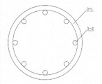
Described chill cage is comprised of a plurality of annulus and complex root reinforcement, and a plurality of annulus are equidistant separately, and the complex root reinforcement is and equidistantly distributes the inner ring that is welded on annulus, by welding annulus and reinforcement is connected into an integral body.After reinforcement was welded on the annulus, an end of reinforcement was concordant with first annulus of chill cage upper end, and the other end of reinforcement stretches out outside last annulus of chill cage lower end, and extension forms an inclined-plane that mates with dummy bar head.
The present invention compared with prior art has following features:
1, simple in structure, the placement of sub-assembly each several part is by manually-operated, and is convenient and reliable;
2, the chill cage is open architecture, opens to water rear molten steel and can in time be full of crystallizer, parcel chill cage, forms fast complete base head, can not scratch copper pipe, sufficient roller and backing roll, and the casting success rate is high;
3, baffle plate and dummy ingot hook are flexibly connected, and the deingot backboard can take off and reuse;
4, owing to not using the sheet iron cylinder, the usage quantity of reinforcing bar reduces, and has reduced production cost.
Below in conjunction with the drawings and specific embodiments detailed structure of the present invention is further described.
Description of drawings
Accompanying drawing 1 is the structural representation of dummy ingot hook;
Accompanying drawing 2 is the left view of accompanying drawing 1;
Accompanying drawing 3 is the structural representation of baffle plate;
Accompanying drawing 4 is the A-A cutaway view in the accompanying drawing 3;
Accompanying drawing 5 is the structural representation of chill cage;
Accompanying drawing 6 is the top view of accompanying drawing 5;
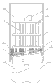
Accompanying drawing 7 uses state reference map for the present invention.
The specific embodiment
A kind of method that adopts the continuous casting ingot guide sub-assembly to carry out continuous casting, described continuous casting ingot guide sub-assembly comprises dummy ingot hook 1, baffle plate 2 and chill cage 3, when the continuous casting ingot guide sub-assembly that uses carries out continuous casting, send dummy bar head 4 to two cold houses first, again dummy ingot hook 1 lower end and cross bar 1-2 are packed in the open slot 4-1 of dummy bar head 4, then dummy bar head 4 continues to enter into crystallizer copper pipe 5 dummy ingot segment process requirement positions, with the slit between asbestos cord 8 plugging dummy bar heads 4 and the crystallizer copper pipe 5, place mat ground floor shot 6 on dummy bar head 4, the surface of ground floor shot 6 forms the inclined-plane with dummy bar head 4 couplings.Baffle plate 2 passes on the ground floor shot layer 6 that is placed on dummy bar head 4 from the elbow 1-1 of dummy ingot hook 1 upper end, place mat second layer shot 7 on baffle plate 2 again, then chill cage 3 is put into the center in the dummy ingot chamber 10 of dummy bar head 4 and crystallizer copper pipe 5 compositions, chill cage 3 lower ends are passed second layer shot 7 and are supported on the baffle plate 2, insert the screw-thread steel section 9 of some in the chill cages 3 again and leave the space, water rear molten steel rapid solidification in order to open.
The continuous casting ingot guide sub-assembly is installed rear beginning casting, open that molten steel is full of rapidly in the crystallizer copper pipe 5 when watering, dummy ingot chamber 10 interior dummy ingot hooks 1 as coolant, chill cage 3, screw-thread steel section 9, ground floor shot layer 6, second layer shot 7 have been accelerated solidifying of molten steel, making molten steel form the base head is connected with dummy bar head 4, under the withdrawal straightening machine traction, the realization strand is produced continuously.Dummy bar head 4 by behind the withdrawal straightening machine with breaking away from the cross bar 1-2 of the dummy ingot hook 1 lower end open slot 4-1 from the dummy bar head 4, then cut away the cross bar 1-2 of dummy ingot hook 1 lower end, take off baffle plate 2 for envelope dummy ingot next time from dummy ingot hook 1.
The continuous casting ingot guide sub-assembly that said method uses comprises dummy ingot hook 1, baffle plate 2 and chill cage 3.
Described dummy ingot hook 1 upper end is provided with an elbow 1-1, arc transition is adopted at elbow 1-1 position, dummy ingot hook 1 lower end is provided with a cross bar 1-2, and cross bar 1-2 is fixed by welding in the lower end of dummy ingot hook 1, the elbow 1-1 of cross bar 1-2 and dummy ingot hook 1 upper end along axis mutually stagger 90 the degree.
Described baffle plate 2 is a disk, and baffle plate 2 is provided with centre bore 2-1, and the diameter of centre bore 2-1 is convenient to dummy ingot hook 1 and is passed baffle plate 2 greater than the diameter of dummy ingot hook 1.
Described chill cage 3 is comprised of three annulus 3-1 and eight reinforcement 3-2, and three annulus 3-1 are equidistant separately, and eight reinforcement 3-2 are and equidistantly distribute the inner ring that is welded on annulus 3-1, by welding annulus 3-1 and reinforcement 3-2 are connected into an integral body.After reinforcement 3-2 is welded on the annulus 3-1, the end of reinforcement 3-2 is concordant with first annulus 3-1 of chill cage 3 upper ends, the other end of reinforcement 3-2 stretches out outside last annulus 3-1 of chill cage 3 lower ends, and extension forms an inclined-plane that mates with dummy bar head 4.
Claims (3)
1. method that adopts the continuous casting ingot guide sub-assembly to carry out continuous casting, it is characterized in that: described continuous casting ingot guide sub-assembly comprises dummy ingot hook, baffle plate and chill cage, when using the continuous casting ingot guide sub-assembly to carry out continuous casting, first dummy bar head is sent to two cold houses, again dummy ingot hook lower end and cross bar are packed in the open slot of dummy bar head, then dummy bar head continues to enter into crystallizer copper pipe dummy ingot segment process requirement position, with the slit between asbestos cord plugging dummy bar head and the crystallizer copper pipe, place mat ground floor shot on dummy bar head, the surface of ground floor shot forms the inclined-plane with the dummy bar head coupling; Baffle plate passes on the ground floor shot layer that is placed on dummy bar head from the elbow of dummy ingot hook upper end, place mat second layer shot on baffle plate again, then the chill cage is put into the center in the dummy ingot chamber of dummy bar head and crystallizer copper pipe composition, chill cage lower end is passed second layer shot and is supported on the baffle plate, insert the screw-thread steel section of some in the chill cage again and leave the space, water rear molten steel rapid solidification in order to open;
The continuous casting ingot guide sub-assembly is installed rear beginning casting, open that molten steel is full of rapidly in the crystallizer copper pipe when watering, dummy ingot hook, chill cage, screw-thread steel section, ground floor shot layer, second layer shot as coolant in the dummy ingot chamber have been accelerated solidifying of molten steel, making molten steel form the base head is connected with dummy bar head, under the withdrawal straightening machine traction, the realization strand is produced continuously;
Dummy bar head by withdrawal straightening machine after with breaking away from the cross bar of the dummy ingot hook lower end open slot from the dummy bar head, then cut away the cross bar of dummy ingot hook lower end, take off baffle plate for envelope dummy ingot next time from the dummy ingot hook.
2. continuous casting ingot guide sub-assembly, it is characterized in that: it comprises dummy ingot hook, baffle plate and chill cage;
Described dummy ingot hook upper end is provided with an elbow, and bend part adopts arc transition, and dummy ingot hook lower end is provided with a cross bar, and cross bar is fixed by welding in the lower end of dummy ingot hook, and the elbow of cross bar and dummy ingot hook upper end mutually staggers along axis and 90 spends;
Described baffle plate is a disk, and baffle plate is provided with centre bore, and the diameter of centre bore is convenient to the dummy ingot hook and is passed baffle plate greater than the diameter of dummy ingot hook;
Described chill cage is comprised of a plurality of annulus and complex root reinforcement, and a plurality of annulus are equidistant separately, and the complex root reinforcement is and equidistantly distributes the inner ring that is welded on annulus, by welding annulus and reinforcement is connected into an integral body; After reinforcement was welded on the annulus, an end of reinforcement was concordant with first annulus of chill cage upper end, and the other end of reinforcement stretches out outside last annulus of chill cage lower end, and extension forms an inclined-plane that mates with dummy bar head.
3. a kind of continuous casting ingot guide sub-assembly according to claim 2, it is characterized in that: described chill cage is comprised of three annulus and eight reinforcements, and three annulus are equidistant separately, and eight reinforcements are and equidistantly distribute the inner ring that is welded on annulus.
Priority Applications (1)
| Application Number | Priority Date | Filing Date | Title |
|---|---|---|---|
| CN201310310208.9A CN103357830B (en) | 2013-07-23 | 2013-07-23 | The method and continuous casting ingot guide sub-assembly of continuous casting are carried out using continuous casting ingot guide sub-assembly |
Applications Claiming Priority (1)
| Application Number | Priority Date | Filing Date | Title |
|---|---|---|---|
| CN201310310208.9A CN103357830B (en) | 2013-07-23 | 2013-07-23 | The method and continuous casting ingot guide sub-assembly of continuous casting are carried out using continuous casting ingot guide sub-assembly |
Publications (2)
| Publication Number | Publication Date |
|---|---|
| CN103357830A true CN103357830A (en) | 2013-10-23 |
| CN103357830B CN103357830B (en) | 2017-11-07 |
Family
ID=49360567
Family Applications (1)
| Application Number | Title | Priority Date | Filing Date |
|---|---|---|---|
| CN201310310208.9A Active CN103357830B (en) | 2013-07-23 | 2013-07-23 | The method and continuous casting ingot guide sub-assembly of continuous casting are carried out using continuous casting ingot guide sub-assembly |
Country Status (1)
| Country | Link |
|---|---|
| CN (1) | CN103357830B (en) |
Cited By (13)
| Publication number | Priority date | Publication date | Assignee | Title |
|---|---|---|---|---|
| CN103934438A (en) * | 2014-04-30 | 2014-07-23 | 江苏理工学院 | Casting method for thick and large steel casting through internal chill |
| CN104226946A (en) * | 2014-09-29 | 2014-12-24 | 天津钢铁集团有限公司 | Blocking method of round billet continuous casting dummy bar head |
| CN104972082A (en) * | 2015-07-13 | 2015-10-14 | 江苏联峰能源装备有限公司 | Casting connector of section dummy bar head |
| CN105436444A (en) * | 2015-12-22 | 2016-03-30 | 芜湖新兴铸管有限责任公司 | Continuous casting blank section casting cold material placing structure and placing method thereof |
| CN106270428A (en) * | 2016-11-10 | 2017-01-04 | 芜湖新兴铸管有限责任公司 | Large-scale continuous casting base section is opened and is watered dummy device and assemble method |
| CN106493317A (en) * | 2016-11-10 | 2017-03-15 | 芜湖新兴铸管有限责任公司 | The large-scale continuous casting base section of high stability is opened and pours dummy device and assemble method |
| CN108188364A (en) * | 2018-03-16 | 2018-06-22 | 山东钢铁股份有限公司 | Large round billet continuous casting dummy device and its application method |
| CN113102700A (en) * | 2021-03-09 | 2021-07-13 | 广东韶钢松山股份有限公司 | Ingot dummy head for continuous casting of square billet |
| CN113477895A (en) * | 2021-07-08 | 2021-10-08 | 攀钢集团攀枝花钢钒有限公司 | Casting starting device for small continuous casting square billet crystallizer and construction method |
| CN114082905A (en) * | 2021-11-24 | 2022-02-25 | 广东韶钢松山股份有限公司 | Connecting assembly for dummy bar head of small square billet and assembling method thereof |
| CN114160765A (en) * | 2021-11-30 | 2022-03-11 | 广东韶钢松山股份有限公司 | Square billet continuous casting dummy ingot assembly and continuous casting method using same |
| CN115055655A (en) * | 2022-05-14 | 2022-09-16 | 江阴兴澄特种钢铁有限公司 | Casting device and method for oversized continuous casting round billet |
| CN115780751A (en) * | 2022-11-18 | 2023-03-14 | 张家港荣盛特钢有限公司 | Dummy ingot device for square billet continuous casting and control method for rapidly packaging dummy ingot head |
Citations (11)
| Publication number | Priority date | Publication date | Assignee | Title |
|---|---|---|---|---|
| US3627017A (en) * | 1968-04-29 | 1971-12-14 | Concast Ag | Dummy bar head for continuous casting and method of using same |
| US4685506A (en) * | 1981-01-27 | 1987-08-11 | Danieli & C. Officine Meccaniche S.P.A. | Billet launching device in continuous casting machines |
| CN2412682Y (en) * | 2000-03-23 | 2001-01-03 | 重庆钢铁(集团)有限责任公司 | Dummy cap |
| CN2417951Y (en) * | 2000-01-31 | 2001-02-07 | 上海宝钢集团公司 | Apparatus for quickly sealing dummy device for continuous casting round and square blank |
| CN201807709U (en) * | 2010-07-29 | 2011-04-27 | 南通宝钢钢铁有限公司 | Crystallizer copper pipe protector of continuous casting machine |
| CN202291318U (en) * | 2011-11-01 | 2012-07-04 | 江苏泰富兴澄特殊钢有限公司 | Continuous casting ingot guide box for small square billet |
| CN202336568U (en) * | 2011-11-16 | 2012-07-18 | 天津钢铁集团有限公司 | Connector for dummy bar head of continuous casting machine |
| CN202447615U (en) * | 2011-12-20 | 2012-09-26 | 鞍钢股份有限公司 | Dummy ingot hook for billet caster |
| CN102847895A (en) * | 2012-09-17 | 2013-01-02 | 中天钢铁集团有限公司 | Ingot guide device for steelmaking continuous casting technique and ingot guide method thereof |
| CN202726006U (en) * | 2012-08-11 | 2013-02-13 | 武钢集团昆明钢铁股份有限公司 | Blank casting dummy ingot device |
| CN203409208U (en) * | 2013-07-23 | 2014-01-29 | 衡阳华菱钢管有限公司 | Continuous casting dummy ingot assembly |
-
2013
- 2013-07-23 CN CN201310310208.9A patent/CN103357830B/en active Active
Patent Citations (11)
| Publication number | Priority date | Publication date | Assignee | Title |
|---|---|---|---|---|
| US3627017A (en) * | 1968-04-29 | 1971-12-14 | Concast Ag | Dummy bar head for continuous casting and method of using same |
| US4685506A (en) * | 1981-01-27 | 1987-08-11 | Danieli & C. Officine Meccaniche S.P.A. | Billet launching device in continuous casting machines |
| CN2417951Y (en) * | 2000-01-31 | 2001-02-07 | 上海宝钢集团公司 | Apparatus for quickly sealing dummy device for continuous casting round and square blank |
| CN2412682Y (en) * | 2000-03-23 | 2001-01-03 | 重庆钢铁(集团)有限责任公司 | Dummy cap |
| CN201807709U (en) * | 2010-07-29 | 2011-04-27 | 南通宝钢钢铁有限公司 | Crystallizer copper pipe protector of continuous casting machine |
| CN202291318U (en) * | 2011-11-01 | 2012-07-04 | 江苏泰富兴澄特殊钢有限公司 | Continuous casting ingot guide box for small square billet |
| CN202336568U (en) * | 2011-11-16 | 2012-07-18 | 天津钢铁集团有限公司 | Connector for dummy bar head of continuous casting machine |
| CN202447615U (en) * | 2011-12-20 | 2012-09-26 | 鞍钢股份有限公司 | Dummy ingot hook for billet caster |
| CN202726006U (en) * | 2012-08-11 | 2013-02-13 | 武钢集团昆明钢铁股份有限公司 | Blank casting dummy ingot device |
| CN102847895A (en) * | 2012-09-17 | 2013-01-02 | 中天钢铁集团有限公司 | Ingot guide device for steelmaking continuous casting technique and ingot guide method thereof |
| CN203409208U (en) * | 2013-07-23 | 2014-01-29 | 衡阳华菱钢管有限公司 | Continuous casting dummy ingot assembly |
Cited By (15)
| Publication number | Priority date | Publication date | Assignee | Title |
|---|---|---|---|---|
| CN103934438A (en) * | 2014-04-30 | 2014-07-23 | 江苏理工学院 | Casting method for thick and large steel casting through internal chill |
| CN103934438B (en) * | 2014-04-30 | 2015-12-30 | 江苏理工学院 | Internal densener is used for the casting method of heavy section steel castings |
| CN104226946A (en) * | 2014-09-29 | 2014-12-24 | 天津钢铁集团有限公司 | Blocking method of round billet continuous casting dummy bar head |
| CN104972082A (en) * | 2015-07-13 | 2015-10-14 | 江苏联峰能源装备有限公司 | Casting connector of section dummy bar head |
| CN105436444A (en) * | 2015-12-22 | 2016-03-30 | 芜湖新兴铸管有限责任公司 | Continuous casting blank section casting cold material placing structure and placing method thereof |
| CN106493317A (en) * | 2016-11-10 | 2017-03-15 | 芜湖新兴铸管有限责任公司 | The large-scale continuous casting base section of high stability is opened and pours dummy device and assemble method |
| CN106270428A (en) * | 2016-11-10 | 2017-01-04 | 芜湖新兴铸管有限责任公司 | Large-scale continuous casting base section is opened and is watered dummy device and assemble method |
| CN108188364A (en) * | 2018-03-16 | 2018-06-22 | 山东钢铁股份有限公司 | Large round billet continuous casting dummy device and its application method |
| CN108188364B (en) * | 2018-03-16 | 2023-09-29 | 山东钢铁股份有限公司 | Dummy ingot device for large round billet continuous casting and use method thereof |
| CN113102700A (en) * | 2021-03-09 | 2021-07-13 | 广东韶钢松山股份有限公司 | Ingot dummy head for continuous casting of square billet |
| CN113477895A (en) * | 2021-07-08 | 2021-10-08 | 攀钢集团攀枝花钢钒有限公司 | Casting starting device for small continuous casting square billet crystallizer and construction method |
| CN114082905A (en) * | 2021-11-24 | 2022-02-25 | 广东韶钢松山股份有限公司 | Connecting assembly for dummy bar head of small square billet and assembling method thereof |
| CN114160765A (en) * | 2021-11-30 | 2022-03-11 | 广东韶钢松山股份有限公司 | Square billet continuous casting dummy ingot assembly and continuous casting method using same |
| CN115055655A (en) * | 2022-05-14 | 2022-09-16 | 江阴兴澄特种钢铁有限公司 | Casting device and method for oversized continuous casting round billet |
| CN115780751A (en) * | 2022-11-18 | 2023-03-14 | 张家港荣盛特钢有限公司 | Dummy ingot device for square billet continuous casting and control method for rapidly packaging dummy ingot head |
Also Published As
| Publication number | Publication date |
|---|---|
| CN103357830B (en) | 2017-11-07 |
Similar Documents
| Publication | Publication Date | Title |
|---|---|---|
| CN103357830A (en) | Method for continuous casting by using continuous casting dummy bar assembly and continuous casting dummy bar assembly | |
| CN101428335B (en) | Continuous casting method for producing round blank with diameter larger than Phi800m on straight continuous casting machine | |
| CN101024229A (en) | Continuous casting, continuous solling production method and apparatus for stainless steel seamless composite pipe | |
| CN203409208U (en) | Continuous casting dummy ingot assembly | |
| CN102248136A (en) | Pouring and breakout preventing technological method for continuous casting | |
| CN208879655U (en) | A kind of continuous cast mold Yarn feeding device | |
| CN101934370B (en) | Process for preparing extra-thick or composite pipe blank by injection moulding and device thereof | |
| CN104259413A (en) | Continuous casting system and process producing large-specification elliptical billets | |
| CN102847895B (en) | Ingot guide device for steelmaking continuous casting technique and ingot guide method thereof | |
| CN203862975U (en) | Cooling frame for capping of tail blanks of continuous casting machine | |
| CN203887184U (en) | Ingot mold for round casting blank with large height-diameter ratio | |
| CN201889398U (en) | Casting device of vertical copper and copper alloy thick-wall hollow casting ingot | |
| CN207840049U (en) | A kind of molten steel casting blank connector | |
| CN102069163B (en) | Crystallizer, device and method for producing casting blank, casting blank and super-large-section casting blank | |
| CN202804119U (en) | Ingot pulling-out device for steel-making continuous-casting process | |
| CN105436444A (en) | Continuous casting blank section casting cold material placing structure and placing method thereof | |
| CN203992295U (en) | Big round billet crystallizer plays cast iron cage | |
| CN102527998A (en) | Preparation method and device for dual-metal multi-layer pipeline | |
| CN105033217A (en) | Continuous casting method | |
| CN202726006U (en) | Blank casting dummy ingot device | |
| CN204934550U (en) | A kind of casting apparatus | |
| CN201913204U (en) | Crystallizer, casting blank production device, casting blank and ultra-large-section casting blank | |
| CN105921705A (en) | Composite die preventing alloy ingot from producing casting shrinkage cavities | |
| CN103611893B (en) | A kind of method and device thereof of filling ingot mold air gap | |
| CN205816754U (en) | A kind of composite die preventing alloy pig from producing casting shrinking hole |
Legal Events
| Date | Code | Title | Description |
|---|---|---|---|
| C06 | Publication | ||
| PB01 | Publication | ||
| C10 | Entry into substantive examination | ||
| SE01 | Entry into force of request for substantive examination | ||
| GR01 | Patent grant | ||
| GR01 | Patent grant |