CN103345983A - Bidirectional wrapping machine of superconductivity strip insulating band - Google Patents
Bidirectional wrapping machine of superconductivity strip insulating band Download PDFInfo
- Publication number
- CN103345983A CN103345983A CN2013102798609A CN201310279860A CN103345983A CN 103345983 A CN103345983 A CN 103345983A CN 2013102798609 A CN2013102798609 A CN 2013102798609A CN 201310279860 A CN201310279860 A CN 201310279860A CN 103345983 A CN103345983 A CN 103345983A
- Authority
- CN
- China
- Prior art keywords
- insulating tape
- wrapped
- pinch rollers
- band
- chain
- Prior art date
- Legal status (The legal status is an assumption and is not a legal conclusion. Google has not performed a legal analysis and makes no representation as to the accuracy of the status listed.)
- Granted
Links
Images


Landscapes
- Superconductors And Manufacturing Methods Therefor (AREA)
Abstract
A bidirectional wrapping machine of a superconductivity strip insulating band is composed of a winding disc, an unwinding disc, two sets of insulating band wrapping discs, two sets of insulating band pressing idler wheels and a set of transmission parts. The winding disc, the unwinding disc, the two sets of insulating band wrapping discs and the two sets of insulating band pressing idler wheels are installed on an operation table. The unwinding disc, the first set of insulating band wrapping discs, the first set of insulating band pressing idler wheels, the second set of insulating band wrapping discs, the second set of insulating band pressing idler wheels and the winding disc are sequentially installed from right to left. The transmission parts are installed below the operation table. The first set of insulating band wrapping discs and the first set of insulating band pressing idler wheels are used for wrapping the superconductivity strip insulating band unidirectionally. The superconductivity strip insulating band is led into the second set of insulating band wrapping discs and the second set of insulating band pressing idler wheels to be wrapped bidirectionally.
Description
Technical field
The present invention relates to a kind of superconducting strip material insulation band lapping device.
Background technology
The insulation of superconducting tape is wrapped to be important in a superconductor applications link, and overlap distance is suitable between requirement insulation belt and the layer, and multilayer is wrapped all the more so, otherwise the irregular phenomenon of thickness can appear in the superconduction band after wrapped.Must do between superconducting tape and the insulating tape in the wrapped process and compress processing, can not leave bubble, otherwise can have influence on insulation effect, more accident may occur in case be applied under the hyperbaric environment.The ultimate tensile stress of superconducting tape is little, and the excessive words of motor pulling force that therefore are used for straining superconducting tape may cause the superconducting tape fracture failure.At present the wrapped machine of insulating tape on the market is all at common cable, and it is wrapped to be that the wrapped tightness degree of cable tightening force or insulating tape all is not suitable for the superconduction tape insulation.
Summary of the invention
The objective of the invention is to overcome the shortcoming that the excessive and insulating tape of the wrapped machine of current insulating tape tightening force in the wrapped process of superconduction band compresses the degree deficiency, propose the two-way wrapped device of a kind of superconducting strip material insulation band.The present invention can realize that the insulating tape multilayer is wrapped, and lay of lapping is adjustable; And make that to compress degree between superconduction band and the insulating tape suitable, retain through the no bubble of check that superconduction band tightening force is moderate in the wrapped process of insulating tape, to superconduction band not damaged.
The concrete technical scheme of the present invention is as follows:
The two-way lapping device of superconducting strip material insulation band of the present invention is made up of take-up reel, draw drum, two groups of wrapped dishes of insulating tape, two groups of insulating tape pinch rollers and a cover running part.According to the wrapped workflow of insulating tape, take-up reel, draw drum, two groups of wrapped dishes of insulating tape and two groups of insulating tape pinch rollers are installed on the operating desk, and erection sequence is turned left from the right side and is successively: draw drum, first group of wrapped dish of insulating tape, first group of insulating tape pinch rollers, second group of wrapped dish of insulating tape, second group of insulating tape pinch rollers, take-up reel.It is wrapped that the first pair of wrapped dish of insulating tape and insulating tape pinch rollers are used for the unidirectional insulating tape of superconducting tape, carries out two-way wrapped second group of wrapped dish of insulating tape and the insulating tape pinch rollers then the superconduction band introduced of superconduction band if desired.
The wrapped dish of insulating tape is the disk of a band hollow straight tube, a superconduction band lead-in wire groove is installed in the hollow straight tube, sprocket wheel is welded on the hollow straight tube middle part, be used for being connected with the running part that is installed on the two-way lapping device operating platform of superconducting strip material insulation band of the present invention bottom, drive the wrapped dish of insulating tape and rotate.The wrapped dish integrated disc portions of insulating tape is equipped with insulating tape anchor clamps, and the insulating tape anchor clamps are used for installing the insulation band, and it is wrapped in running the superconduction band to be carried out insulating tape.
Insulating tape pinch rollers device has two insulating tape pinch rollers up and down, following pinch rollers is fixed, under compress a sprocket wheel be installed on the roller shaft, be used for being connected with the running part that is installed on the two-way lapping device operating platform of superconducting strip material insulation band of the present invention bottom, drive insulating tape pinch rollers device and rotate.But last pinch rollers up-down adjustment position.
Running part is installed in the below of the two-way lapping device operating desk of superconducting strip material insulation band of the present invention, and running part is made up of change gear box, forward power transmission shaft, reverse drive axle, reverse gear group, master control motor, the wrapped driving-chain of reverse isolation band, the wrapped driving-chain of forward insulating tape and insulating tape pinch rollers driving-chain.Change gear box is installed under the two-way lapping device operating desk of the superconducting strip material insulation band of the present invention left side, the master control motor is installed under the two-way lapping device operating desk of the superconducting strip material insulation band of the present invention right side, is connected by the forward power transmission shaft between change gear box and the master control motor.Forward power transmission shaft below is the reverse drive axle, between forward power transmission shaft below and the reverse drive axle a pair of reverse gear group is installed; The wrapped driving-chain of forward insulating tape is installed under first group of wrapped dish of insulating tape, and the wrapped driving-chain of reverse isolation band is installed under second group of wrapped dish of insulating tape, and insulating tape pinch rollers driving-chain is installed in the change gear box side.
Master control motor output speed is delivered to change gear box by the forward power transmission shaft, master control motor output speed is delivered on first group of insulating tape pinch rollers by insulating tape pinch rollers driving-chain after slowing down through change gear box, and drives first group of insulating tape pinch rollers rotation; Master control motor output speed is delivered on first group of wrapped dish of insulating tape by the wrapped driving-chain of forward insulating tape that is installed between forward power transmission shaft and the first group of wrapped dish of insulating tape, and drives first group of wrapped dish of insulating tape and rotate; Master control motor output speed is delivered on the reverse drive axle by the reverse gear group that is installed between forward power transmission shaft and the reverse drive axle, be delivered on second group of wrapped dish of insulating tape by the wrapped driving-chain of reverse isolation band that is installed between reverse drive axle and the second group of wrapped dish of insulating tape again, and drive second group of wrapped dish of insulating tape and rotate.
The course of work of the present invention is as follows:
It is unidirectional when wrapped to carry out the superconducting strip material insulation band, be wound on not wrapped superconduction tape leader on the draw drum earlier, draw drum with the good superconduction band of coiling is installed on the two-way lapping device of superconducting strip material insulation band of the present invention right side then, the reverse gear group of the two-way lapping device running part of superconducting strip material insulation band of the present invention is thrown off, make the wrapped driving-chain of reverse isolation band be in halted state, open the two-way lapping device running part of superconducting strip material insulation band of the present invention then.The superconduction band that is wound on the draw drum is pulled out the wrapped dish of introducing insulating tape from draw drum.The wrapped dish of insulating tape is the disk of a band hollow straight tube, a superconduction band lead-in wire groove is installed in the hollow straight tube, sprocket wheel is welded on the middle part of hollow straight tube, be connected with the running part of the two-way lapping device of superconducting strip material insulation band of the present invention that is installed on the operating platform bottom, drive the wrapped dish of insulating tape and rotate.Insulating tape anchor clamps on the wrapped dish disk of insulating tape carry out insulating tape to the superconduction band in running wrapped.
Superconduction band behind the lapped insulation band is introduced insulating tape pinch rollers device, insulating tape pinch rollers device has two insulating tape pinch rollers up and down, following pinch rollers is fixed, under compress a sprocket wheel be installed on the roller shaft, be used for being connected with the running part that is installed on the two-way lapping device of operating platform bottom superconducting strip material insulation band, drive insulating tape pinch rollers device and rotate.But last pinch rollers up-down adjustment position, superconduction band after insulating tape is wrapped is from passing through between two insulating tape pinch rollers up and down, by the tightness of regulating pinch rollers the superconduction band is compressed, eliminate the bubble between superconduction band and the insulating tape, and move the mutually frictional force that produces of two pinch rollers can drive superconduction and takes to preceding motion up and down.So far the unidirectional wrapped process of superconducting strip material insulation band is finished.
Carry out two-way wrapped if desired, the reverse gear group of the two-way lapping device running part of superconducting strip material insulation band of the present invention is meshed together, make the wrapped driving-chain of reverse isolation band in running order, open the two-way lapping device running part of superconducting strip material insulation band of the present invention then, the unidirectional wrapped insulation band of finishing is introduced second group of wrapped dish of insulating tape and insulating tape pinch rollers, and to carry out two-way insulating tape wrapped, at last with wrapped good superconduction band coiling to wire spool, finish the wrapped process of whole insulating tape.
Description of drawings
Fig. 1 a, Fig. 1 b are draw drum, take-up reel structure chart, and wherein Fig. 1 a is front view, and Fig. 1 b is end view;
Fig. 2 a, Fig. 2 b are the wrapped dish structure chart of insulating tape, and wherein Fig. 2 a is front view, and Fig. 2 b is end view;
Fig. 3 a, Fig. 3 b are the wire spool structure chart, and wherein Fig. 3 a is front view, and Fig. 3 b is end view;
Fig. 4 is superconduction band lead-in wire groove structure chart;
Fig. 5 a, Fig. 5 b are insulating tape clamp structure figure, and wherein Fig. 5 a is end view, and Fig. 5 b is stereogram;
Fig. 6 a, Fig. 6 b are insulating tape pinch rollers structure chart, and wherein Fig. 6 a is front view, and Fig. 6 b is end view;
Fig. 7 is pressure roller structure figure;
Fig. 8 a, Fig. 8 b are stainless steel understructure figure, and wherein Fig. 8 a is front view, and Fig. 8 b is vertical view;
Fig. 9 is the running part structure chart;
Figure 10 a, Figure 10 b are master control motor schematic diagram, and wherein Figure 10 a is front view, and Figure 10 b is right view.
Embodiment
The two-way lapping device of superconducting strip material insulation band of the present invention is made up of take-up reel, draw drum, two groups of wrapped dishes of insulating tape, two groups of insulating tape pinch rollers and a cover running part.According to the wrapped workflow of insulating tape, take-up reel, draw drum, two groups of wrapped dishes of insulating tape and two groups of insulating tape pinch rollers erection sequence on the two-way lapping device operating desk of superconducting strip material insulation band of the present invention are turned left from the right side and are successively: draw drum, first group of wrapped dish of insulating tape, first group of insulating tape pinch rollers, second group of wrapped dish of insulating tape, second group of insulating tape pinch rollers, take-up reel.It is wrapped that the first pair of wrapped dish of insulating tape and insulating tape pinch rollers are used for the unidirectional insulating tape of superconducting tape, carries out two-way wrapped second group of wrapped dish of insulating tape and the insulating tape pinch rollers then the superconduction band introduced of superconduction band if desired.Running part is installed in the below of the two-way lapping device operating desk of superconducting strip material insulation band of the present invention.
The invention will be further described below in conjunction with the drawings and specific embodiments:
The structure of described take-up reel, draw drum is shown in Fig. 1 a and Fig. 1 b.The structure of take-up reel and draw drum is identical, by two wooden baffle plates 101,102 and superconduction band coiling plate 103 form.The superconduction band is wound on the superconduction band coiling plate 103, and the two wooden baffle plates 101,102 that are positioned at superconduction band coiling plate 103 left and right sides can prevent that the superconduction band from scattering.
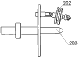
The wrapped dish of described insulating tape is made up of wire spool 201, insulating tape anchor clamps 202 and superconduction band lead-in wire groove 203 shown in Fig. 2 a and Fig. 2 b.Wire spool 201 is disks of a band hollow straight tube, and internal thread is arranged in the hollow straight tube.Insulating tape anchor clamps 202 are installed on the disk of wire spool 201, and superconduction band lead-in wire groove 203 is installed in the hollow straight tube of wire spool 201.
Described wire spool 201 is shown in Fig. 3 a and Fig. 3 b, formed by disk 301, hollow straight tube 302 and sprocket wheel 303, disk 301 centers have a circular hole, hollow straight tube 302 is stuck in described circular hole place, disk 301 and hollow straight tube 302 are welded together, sprocket wheel 303 is welded on the axial middle part of hollow straight tube 302, is used for being connected with the running part of the two-way lapping device of superconducting strip material insulation band of the present invention.Hollow straight tube 302 has internal thread, is used for installing superconduction band lead-in wire groove 203.Have four screwed holes that have nothing in common with each other apart from the disc centre distance on the disk 301, be used for installing insulating tape anchor clamps 202.
Described superconduction band goes between groove 203 as shown in Figure 4, and superconduction band lead-in wire groove 203 is four fluorine tubes of a hollow, and 401 are the lead channels of superconduction band, and the superconduction band passes from lead channels 401.The outer wall of superconduction band lead-in wire groove has screw thread 402, is used for being connected with internal thread on the hollow straight tube 302.
Described insulating tape anchor clamps 202 are shown in Fig. 5 a and Fig. 5 b, and insulating tape anchor clamps 202 are made up of two insulating tape pressing plates 501,502, adjustment nut 503 and connecting rod 504.Insulating tape is placed between two insulating tape pressing plates 501,502, adjusting nut 503 is installed on the insulating tape pressing plate 502, by adjusting the degree that compresses that nut 503 is regulated insulating tapes, screwed connecting rod 504 is installed on the screwed hole of disk 301 of wire spool 201.
Described insulating tape pinch rollers is made up of last pinch rollers 601, movable axis bearing 602, stainless steel base 603, elasticity bolt 604, sprocket wheel 605 and following pinch rollers 606 shown in Fig. 6 a and 6b.Stainless steel base 603 is installed on the operating desk of the two-way lapping device of superconducting strip material insulation band of the present invention, last pinch rollers 601 is installed on the movable axis bearing 602, movable axis bearing 602 is installed on the stainless steel base 603, elasticity bolt 604 is installed in stainless steel base 603 tops, and last pinch rollers 601 is by elasticity bolt 604 up-down adjustment positions; Following pinch rollers 606 is installed on the stainless steel base 603, and sprocket wheel 605 is installed in down on the axle of pinch rollers 606.
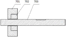
Described upward pinch rollers 601 is identical with following pinch rollers 606 structures, and as shown in Figure 7, last pinch rollers 601 and following pinch rollers 606 are formed by cover 702 in rubber wheel 701, the stainless steel and connecting axle 703.Cover 702 is embedded in the rubber wheel 701 in the stainless steel, bonds together by seccotine and rubber wheel 701.Connecting axle 703 cover 702 centre bores in rubber wheel 701 and the stainless steel pass, and and stainless steel in cover 702 weld together.Connecting axle 703 axial directions have keyway, are used for installing sprocket wheel 605.The insulating tape pinch rollers is connected with the running part of the two-way lapping device of superconducting strip material insulation band of the present invention by sprocket wheel 605, drives whole insulating tape pinch rollers device motion.
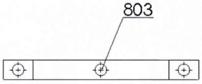
Described stainless steel base 603 is shown in Fig. 8 a and Fig. 8 b.There are notch 801 and three fixed vias 802 of three road activities stainless steel base 603 sides.Last pinch rollers 601 is installed in 801 li in movable notch, but the tightness of up-down adjustment insulating tape, and following pinch rollers 606 is installed in 802 li of fixed vias.Elasticity bolt installing hole 803 is arranged at stainless steel base 603 tops, and elasticity bolt installing hole 803 is installed elasticity bolt 604.
Described running part is made up of change gear box 901, forward power transmission shaft 902, reverse drive axle 903, reverse gear group 904, master control motor 905, the wrapped driving-chain 906 of reverse isolation band, the wrapped driving-chain 907 of forward insulating tape and insulating tape pinch rollers driving-chain 908 as shown in Figure 9.
Described master control motor 905 is shown in Figure 10 a and Figure 10 b, and 1001 is forward power transmission shaft 902 connectors, and 1002 is no-load voltage ratio deceleration delivery outlet.Insulating tape pinch rollers driving-chain 908 is made up of a sprocket wheel and a chain, and sprocket wheel is installed on the no-load voltage ratio deceleration delivery outlet 1002 of master control motor 905, and sprocket wheel on chain and the insulating tape pinch rollers device lower pressure wheel 606 605 is connected by chain.
Claims (10)
1. two-way wrapped machine of superconducting strip material insulation band is characterized in that: described wrapped machine is made up of take-up reel, draw drum, two groups of wrapped dishes of insulating tape, two groups of insulating tape pinch rollers and a cover running part; Take-up reel, draw drum, two groups of wrapped dishes of insulating tape and two groups of insulating tape pinch rollers are installed on the operating desk, and erection sequence is turned left from the right side and is successively: draw drum, first group of wrapped dish of insulating tape, first group of insulating tape pinch rollers, second group of wrapped dish of insulating tape, second group of insulating tape pinch rollers, take-up reel; Running part is installed in the below of operating desk.
2. the two-way wrapped machine of superconducting strip material insulation band according to claim 1 is characterized in that: described take-up reel, draw drum structure are identical, form by wooden baffle plate (101,102) and superconduction band coiling plate (103); Two wooden baffle plates (101,102) are positioned at the left and right sides of superconduction band coiling plate (103), and the superconduction band is wound on the superconduction band coiling plate (103).
3. the two-way wrapped machine of superconducting strip material insulation band according to claim 1 is characterized in that: the wrapped dish of described insulating tape is made up of wire spool (201), insulating tape anchor clamps (202) and superconduction band lead-in wire groove (203); Wire spool (201) is the disk of a band hollow straight tube, in the described hollow straight tube internal thread is arranged; Insulating tape anchor clamps (202) are installed on the disk of wire spool (201), and superconduction band lead-in wire groove (203) is installed in the hollow straight tube of wire spool (201).
4. the two-way wrapped machine of superconducting strip material insulation band according to claim 1, it is characterized in that: described wire spool is made up of disk (301), hollow straight tube (302) and sprocket wheel (303); Disk (301) center has a circular hole, and hollow straight tube (302) is stuck in described circular hole place, and disk (301) and hollow straight tube (302) weld together; Sprocket wheel (303) is welded on hollow straight tube (302) middle part, is used for being connected with the running part of the two-way lapping device of described superconducting strip material insulation band; Hollow straight tube (302) has internal thread, is used for installing superconduction band lead-in wire groove (203); Have four screwed holes that have nothing in common with each other apart from the disc centre distance on the disk (301), be used for installing insulating tape anchor clamps (202).
5. the two-way wrapped machine of superconducting strip material insulation band according to claim 1, it is characterized in that: described superconduction band lead-in wire groove (203) is the four fluorine tube of a hollow, superconduction band lead-in wire groove outer wall has external screw thread, is used for being connected with internal thread on the hollow straight tube (302).
6. the two-way wrapped machine of superconducting strip material insulation band according to claim 1, it is characterized in that: described insulating tape anchor clamps (202) are made up of two insulating tape pressing plates (501,502), adjustment nut (503) and connecting rod (504), and insulating tape is placed between two insulating tape pressing plates (501,502); Adjust nut (503) and be installed on the insulating tape pressing plate (502), regulate the degree that compresses of insulating tape by adjusting nut (503), threaded connecting rod (504) is installed on the screwed hole of disk (301) of wire spool (201).
7. the two-way wrapped machine of superconducting strip material insulation band according to claim 1, it is characterized in that: described insulating tape pinch rollers is made up of last pinch rollers (601), movable axis bearing (602), stainless steel base (603), elasticity bolt (604), sprocket wheel (605) and following pinch rollers (606); Stainless steel base (603) is installed on the operating desk of the two-way lapping device of superconducting strip material insulation band of the present invention; Last pinch rollers (601) is installed on the movable axis bearing (602), movable axis bearing (602) is installed on the stainless steel base (603), elasticity bolt (604) is installed in stainless steel base (603) top, and last pinch rollers (601) is by elasticity bolt (604) up-down adjustment position; Following pinch rollers (606) is installed on the stainless steel base (603), and sprocket wheel (605) is installed in down on the axle of pinch rollers (606).
8. the two-way wrapped machine of superconducting strip material insulation band according to claim 1, it is characterized in that: described upward pinch rollers (601) is identical with following pinch rollers (606) structure, and last pinch rollers (601) and following pinch rollers (606) are formed by cover (702) and connecting axle (703) in rubber wheel (701), the stainless steel; Cover (702) is embedded in the rubber wheel (701) in the stainless steel, bonds together with rubber wheel (701); Connecting axle (703) passes from the centre bore of rubber wheel (701) and the interior cover of stainless steel (702), and welds together with the interior cover of stainless steel (702); Connecting axle (703) axial direction has keyway, is used for installing sprocket wheel (605); The insulating tape pinch rollers is connected with the running part of the two-way lapping device of described superconducting strip material insulation band by sprocket wheel (605), drives whole insulating tape pinch rollers device motion.
9. the two-way wrapped machine of superconducting strip material insulation band according to claim 1, it is characterized in that: there are notch (801) and three fixing through holes (802) of three road activities the side of described stainless steel base (603); Last pinch rollers 601 is installed in movable notch (801) lining, and following pinch rollers (606) is installed in fixed via (802) lining; Elasticity bolt installing hole (803) is arranged at stainless steel base (603) top, and elasticity bolt installing hole (803) is installed elasticity bolt (604).
10. the two-way wrapped machine of superconducting strip material insulation band according to claim 1, it is characterized in that: described running part is made up of change gear box (901), forward power transmission shaft (902), reverse drive axle (903), reverse gear group (904), master control motor (905), the wrapped driving-chain of reverse isolation band (906), the wrapped driving-chain of forward insulating tape (907) and insulating tape pinch rollers driving-chain (908); Change gear box (901) is installed under the two-way lapping device operating desk of the described superconducting strip material insulation band left side; Master control motor (905) is installed under the two-way lapping device operating desk of the described superconducting strip material insulation band right side; Forward power transmission shaft (902) is installed between change gear box (901) and the master control motor (905); Reverse drive axle (903) is installed in the below of forward power transmission shaft (902); Reverse gear group (904) is made up of a pair of gear, cogs to be installed on the forward power transmission shaft (902), and lower gear is installed on the reverse drive axle (903); The wrapped driving-chain of forward insulating tape (907) is made up of a sprocket wheel and a chain, and sprocket wheel is installed on the forward power transmission shaft (902); Sprocket wheel is connected by chain with sprocket wheel (303) on the hollow straight tube (302); Master control motor (905) drives first group of wrapped dish of insulating tape by the wrapped driving-chain of forward insulating tape (907) and rotates wrapped; The wrapped driving-chain of reverse isolation band (906) is identical with the wrapped driving-chain of forward insulating tape (907) structure, and the sprocket wheel of the wrapped driving-chain of reverse isolation band (906) is installed on the reverse drive axle (903), is connected with second group of wrapped dish of insulating tape by chain; Insulating tape pinch rollers driving-chain (908) is made up of a sprocket wheel and a chain, sprocket wheel is installed on the no-load voltage ratio deceleration delivery outlet (1002) of master control motor (905), and the sprocket wheel (605) under chain and the insulating tape pinch rollers on the pinch rollers (606) is connected by chain.
Priority Applications (1)
| Application Number | Priority Date | Filing Date | Title |
|---|---|---|---|
| CN201310279860.9A CN103345983B (en) | 2013-07-04 | 2013-07-04 | The two-way winding machine of superconducting strip material insulation band |
Applications Claiming Priority (1)
| Application Number | Priority Date | Filing Date | Title |
|---|---|---|---|
| CN201310279860.9A CN103345983B (en) | 2013-07-04 | 2013-07-04 | The two-way winding machine of superconducting strip material insulation band |
Publications (2)
| Publication Number | Publication Date |
|---|---|
| CN103345983A true CN103345983A (en) | 2013-10-09 |
| CN103345983B CN103345983B (en) | 2015-11-04 |
Family
ID=49280772
Family Applications (1)
| Application Number | Title | Priority Date | Filing Date |
|---|---|---|---|
| CN201310279860.9A Expired - Fee Related CN103345983B (en) | 2013-07-04 | 2013-07-04 | The two-way winding machine of superconducting strip material insulation band |
Country Status (1)
| Country | Link |
|---|---|
| CN (1) | CN103345983B (en) |
Cited By (2)
| Publication number | Priority date | Publication date | Assignee | Title |
|---|---|---|---|---|
| CN111554453A (en) * | 2020-05-07 | 2020-08-18 | 安徽英杰精工机械有限公司 | Vertical wrapping machine for cable processing |
| CN112951519A (en) * | 2021-03-16 | 2021-06-11 | 国家电网有限公司 | Flame retarded cable apparatus for producing |
Citations (5)
| Publication number | Priority date | Publication date | Assignee | Title |
|---|---|---|---|---|
| US1594492A (en) * | 1925-03-03 | 1926-08-03 | Acme Wire Co | Electric-wire-wrapping machine |
| CN201348898Y (en) * | 2008-12-31 | 2009-11-18 | 湖北鄂电萃宇电缆有限公司 | Concentric cable refractory layer wrapping machine |
| CN101630548A (en) * | 2009-08-11 | 2010-01-20 | 河南省电力公司新乡供电公司 | Stranding machine lapping device |
| CN201498269U (en) * | 2009-08-07 | 2010-06-02 | 常熟市豪威富机械制造有限公司 | Thin film silk wrapping machine |
| CN202871408U (en) * | 2012-11-12 | 2013-04-10 | 天津市信九电子有限公司 | Double-wrapping machine |
-
2013
- 2013-07-04 CN CN201310279860.9A patent/CN103345983B/en not_active Expired - Fee Related
Patent Citations (5)
| Publication number | Priority date | Publication date | Assignee | Title |
|---|---|---|---|---|
| US1594492A (en) * | 1925-03-03 | 1926-08-03 | Acme Wire Co | Electric-wire-wrapping machine |
| CN201348898Y (en) * | 2008-12-31 | 2009-11-18 | 湖北鄂电萃宇电缆有限公司 | Concentric cable refractory layer wrapping machine |
| CN201498269U (en) * | 2009-08-07 | 2010-06-02 | 常熟市豪威富机械制造有限公司 | Thin film silk wrapping machine |
| CN101630548A (en) * | 2009-08-11 | 2010-01-20 | 河南省电力公司新乡供电公司 | Stranding machine lapping device |
| CN202871408U (en) * | 2012-11-12 | 2013-04-10 | 天津市信九电子有限公司 | Double-wrapping machine |
Cited By (3)
| Publication number | Priority date | Publication date | Assignee | Title |
|---|---|---|---|---|
| CN111554453A (en) * | 2020-05-07 | 2020-08-18 | 安徽英杰精工机械有限公司 | Vertical wrapping machine for cable processing |
| CN112951519A (en) * | 2021-03-16 | 2021-06-11 | 国家电网有限公司 | Flame retarded cable apparatus for producing |
| CN112951519B (en) * | 2021-03-16 | 2022-06-24 | 国家电网有限公司 | Flame retarded cable apparatus for producing |
Also Published As
| Publication number | Publication date |
|---|---|
| CN103345983B (en) | 2015-11-04 |
Similar Documents
| Publication | Publication Date | Title |
|---|---|---|
| CN207361659U (en) | A kind of new shift automatic cable arranging device | |
| CN101269563B (en) | Superposition enclosing apparatus for continuous long expanded polytetrafluoroethylene sealing material | |
| CN101872665B (en) | Six-reel steel band armouring machine | |
| CN1881484A (en) | High-temperature superconducting cable coiling machine and cable coiling method | |
| CN106128641B (en) | Cable stranding machine | |
| CN104528561B (en) | Combined marine winch | |
| CN206840688U (en) | A kind of compound pipe enhancement layer wind | |
| WO2022041747A1 (en) | Auxiliary wire feeding apparatus for motor winding | |
| CN110610784A (en) | Wrapping machine for cable production line | |
| CN103345983A (en) | Bidirectional wrapping machine of superconductivity strip insulating band | |
| CN103625995B (en) | Can the identical tension formula cable drum device of flexible take-up | |
| CN203582135U (en) | Wire automatic stopping output device | |
| CN110371724A (en) | A kind of micro- drawing-off automatic flexible unwinding device and its discharging method | |
| CN107415210B (en) | A kind of compound pipe enhancement layer wind | |
| CN117263069A (en) | OHT suspension type lifting system and hoisting transmission mechanism thereof | |
| CN207328896U (en) | A kind of automatic tape winding machine | |
| CN113085223A (en) | Automatic flat plate tape laying equipment and control method thereof | |
| CN104269269A (en) | Insulating layer assembly device | |
| CN210944054U (en) | Multilayer gauze covering device | |
| CN107499555A (en) | A kind of automatic tape winding machine | |
| CN208666964U (en) | Rope guider for winding drum double-layer winding steel wire rope | |
| CN111799032A (en) | Outer cladding layer winding equipment of cable | |
| CN203754085U (en) | Six-disk nonmetallic belt winding machine | |
| CN221225909U (en) | Cable core cladding forming device for cable processing | |
| CN116564626B (en) | Fire-resistant mica tape wrapping machine for power cable |
Legal Events
| Date | Code | Title | Description |
|---|---|---|---|
| C06 | Publication | ||
| PB01 | Publication | ||
| C10 | Entry into substantive examination | ||
| SE01 | Entry into force of request for substantive examination | ||
| C14 | Grant of patent or utility model | ||
| GR01 | Patent grant | ||
| CF01 | Termination of patent right due to non-payment of annual fee | ||
| CF01 | Termination of patent right due to non-payment of annual fee |
Granted publication date: 20151104 Termination date: 20160704 |