CN103328362A - Stop sequencing for braking device - Google Patents
Stop sequencing for braking device Download PDFInfo
- Publication number
- CN103328362A CN103328362A CN2011800667306A CN201180066730A CN103328362A CN 103328362 A CN103328362 A CN 103328362A CN 2011800667306 A CN2011800667306 A CN 2011800667306A CN 201180066730 A CN201180066730 A CN 201180066730A CN 103328362 A CN103328362 A CN 103328362A
- Authority
- CN
- China
- Prior art keywords
- drg
- brake
- brake coil
- control device
- elevator
- Prior art date
- Legal status (The legal status is an assumption and is not a legal conclusion. Google has not performed a legal analysis and makes no representation as to the accuracy of the status listed.)
- Granted
Links
Images
Classifications
-
- B—PERFORMING OPERATIONS; TRANSPORTING
- B66—HOISTING; LIFTING; HAULING
- B66B—ELEVATORS; ESCALATORS OR MOVING WALKWAYS
- B66B1/00—Control systems of elevators in general
- B66B1/24—Control systems with regulation, i.e. with retroactive action, for influencing travelling speed, acceleration, or deceleration
- B66B1/28—Control systems with regulation, i.e. with retroactive action, for influencing travelling speed, acceleration, or deceleration electrical
- B66B1/32—Control systems with regulation, i.e. with retroactive action, for influencing travelling speed, acceleration, or deceleration electrical effective on braking devices, e.g. acting on electrically controlled brakes
-
- B—PERFORMING OPERATIONS; TRANSPORTING
- B66—HOISTING; LIFTING; HAULING
- B66B—ELEVATORS; ESCALATORS OR MOVING WALKWAYS
- B66B5/00—Applications of checking, fault-correcting, or safety devices in elevators
- B66B5/02—Applications of checking, fault-correcting, or safety devices in elevators responsive to abnormal operating conditions
-
- F—MECHANICAL ENGINEERING; LIGHTING; HEATING; WEAPONS; BLASTING
- F16—ENGINEERING ELEMENTS AND UNITS; GENERAL MEASURES FOR PRODUCING AND MAINTAINING EFFECTIVE FUNCTIONING OF MACHINES OR INSTALLATIONS; THERMAL INSULATION IN GENERAL
- F16D—COUPLINGS FOR TRANSMITTING ROTATION; CLUTCHES; BRAKES
- F16D63/00—Brakes not otherwise provided for; Brakes combining more than one of the types of groups F16D49/00 - F16D61/00
- F16D63/002—Brakes with direct electrical or electro-magnetic actuation
Landscapes
- Engineering & Computer Science (AREA)
- Automation & Control Theory (AREA)
- General Engineering & Computer Science (AREA)
- Mechanical Engineering (AREA)
- Elevator Control (AREA)
Abstract
Description
技术领域 technical field
本公开内容通常涉及制动装置,且具体而言,涉及与电梯一起使用的制动装置。 The present disclosure relates generally to braking devices, and in particular, to braking devices for use with elevators.
背景技术 Background technique
在现代社会,电梯已经变成用于运送人和货物经过多层建筑物的普遍存在的机器。由于电梯整天都在连续地操作,在各个楼层处进行频繁停止,因而电梯的制动系统在电梯的平稳操作中起着重要作用。 In modern society, elevators have become ubiquitous machines for transporting people and goods through multistory buildings. Since elevators operate continuously throughout the day with frequent stops at various floors, the braking system of the elevator plays an important role in the smooth operation of the elevator.
使用带驱动或绳索驱动的系统以升起或降下电梯轿厢的牵引机器(如,电梯系统中使用的那些)通常使用机械的或机电的制动系统来停止或暂时保持特定的动作。例如,电梯的机电制动器通常利用离合器型制动机构,以用于供应足以使电梯轿厢减慢或保持在固定位置的保持转矩或制动转矩。由离合器型制动器供应的制动转矩可由刚性地附接至机器轴的旋转制动盘与可释放地放置成与制动盘的表面接触的一组摩擦垫之间生成的摩擦机械地产生。摩擦垫的接合或解除接合由制动器线圈机电地控制。当制动器线圈被启动时,电枢板与电磁核芯之间的磁吸力引起摩擦垫与制动盘的表面解除接合。当制动器线圈停用时,接合电枢板的弹簧将电枢板推动成与制动盘的表面相接合。尽管已经证明此类离合器型制动器是有效的,且现今仍广泛用于各种牵引应用(如,电梯等)中,但其仍具有改善的空间。 Traction machines, such as those used in elevator systems, that use belt-driven or rope-driven systems to raise or lower elevator cars typically use mechanical or electromechanical braking systems to stop or temporarily hold certain motions. For example, electromechanical brakes for elevators typically utilize a clutch-type braking mechanism for supplying a holding or braking torque sufficient to slow or hold the elevator car in a fixed position. The braking torque supplied by a clutch-type brake may be mechanically produced by friction generated between a rotating brake disc rigidly attached to a machine shaft and a set of friction pads releasably placed in contact with the surface of the brake disc. Engagement or disengagement of the friction pads is electromechanically controlled by brake coils. When the brake coil is activated, the magnetic attraction between the armature plate and the electromagnetic core causes the friction pads to disengage from the surface of the brake disc. When the brake coil is deactivated, a spring engaging the armature plate pushes the armature plate into engagement with the surface of the brake disc. Although such clutch-type brakes have proven effective and are still widely used today in various traction applications (eg, elevators, etc.), there is still room for improvement.
例如,离合器型制动器不可取决于所需要的停止类型(例如,紧急停止对正常停止)而选择性地施加不同量的力来停止电梯。典型离合器型制动器限于其额定转矩,该额定转矩还由制动器的机械极限、其摩擦垫的材料成分等规定。在紧急状况期间,如,通向建筑物的电力损失,制动系统必须快速地停止电梯。此类紧急停止通常为突然的,且引起电梯轿厢带有急停的停止,这可能对电梯轿厢内搭乘的乘客是不适的经历。由于电梯制动系统对正常停止提供与其对紧急停止所提供的相同的制动转矩,因而每当制动系统用以针对紧急停止而停止电梯时,电梯轿厢和轿厢内的乘客可能经历急停。因此,由此可见,离合器型制动器没有提供用以停止电梯的制动力的控制或变化。 For example, clutch-type brakes cannot selectively apply different amounts of force to stop an elevator depending on the type of stop required (eg, emergency stop versus normal stop). A typical clutch-type brake is limited by its rated torque, which is also dictated by the mechanical limits of the brake, the material composition of its friction pads, and the like. During an emergency, such as a loss of power to the building, the braking system must quickly stop the elevator. Such emergency stops are often sudden and cause the elevator car to stop with an emergency stop, which can be an uncomfortable experience for passengers riding in the elevator car. Since the elevator braking system provides the same braking torque for a normal stop as it does for an emergency stop, whenever the braking system is used to stop the elevator for an emergency stop, the elevator car and the passengers in the car may experience Emergency stop. Thus, it follows that clutch-type brakes do not provide control or variation of the braking force to stop the elevator.
鉴于前述内容,继续寻求改善,以用于提供有效的制动系统来安全地停止电梯,同时提高停止对于乘客的舒适度。 In view of the foregoing, improvements continue to be sought for providing effective braking systems for safely stopping elevators while increasing the comfort of stopping for passengers.
发明内容 Contents of the invention
根据本公开内容的一个方面,公开了一种电梯系统。电梯系统可包括轿厢、具有第一磁性制动器线圈的第一制动器和具有制动器电源的制动器控制装置。第一制动器可在解除接合位置与接合位置之间移动。制动器控制装置可电连接到第一制动器,且可构造成利用来自第一制动器线圈的第一剩余电流来选择性地延迟第一制动器向接合位置的移动。第一制动器可构造成在第一制动器线圈被制动器电源激励时可移动到解除接合位置,且可构造成在第一制动器线圈被解除激励时可移动到接合位置。第一剩余电流可通过减慢第一制动器线圈内的储存能量的衰减速率来延迟第一制动器向接合位置的移动。在实施例中,该延迟可在大约150毫秒到大约600毫秒的范围内。在一些实施例中,第一制动器向接合位置的移动可响应于电梯轿厢的无意移动而延迟。 According to one aspect of the present disclosure, an elevator system is disclosed. An elevator system may include a car, a first brake having a first magnetic brake coil, and a brake control having a brake power supply. The first brake is movable between a disengaged position and an engaged position. A brake control device may be electrically connected to the first brake and may be configured to utilize a first residual current from the first brake coil to selectively delay movement of the first brake to the engaged position. The first brake may be configured to be movable to a disengaged position when the first brake coil is energized by the brake power source, and may be configured to be movable to an engaged position when the first brake coil is de-energized. The first residual current may delay movement of the first brake to the engaged position by slowing the rate of decay of stored energy within the first brake coil. In an embodiment, the delay may be in the range of about 150 milliseconds to about 600 milliseconds. In some embodiments, movement of the first brake to the engaged position may be delayed in response to inadvertent movement of the elevator car.
在一些实施例中,电梯系统还包括具有第二磁性制动器线圈的第二制动器。第二制动器可电连接到制动器控制装置,且可在解除接合位置与接合位置之间移动。第二制动器可具有第二磁性制动器线圈。第二制动器在第二制动器线圈被制动器电源激励时可从接合位置移动到解除接合位置。第二制动器可构造成在第二制动器线圈被解除激励时可移动到接合位置。在实施例中,制动器控制装置可构造成利用来自第二制动器线圈的第二剩余电流来选择性地延迟第二制动器向接合位置的移动。 In some embodiments, the elevator system also includes a second brake having a second magnetic brake coil. A second brake is electrically connectable to the brake control device and movable between a disengaged position and an engaged position. The second brake may have a second magnetic brake coil. The second brake is movable from an engaged position to a disengaged position when the second brake coil is energized by the brake power supply. The second brake may be configured to be movable to an engaged position when the second brake coil is de-energized. In an embodiment, the brake control device may be configured to utilize the second residual current from the second brake coil to selectively delay movement of the second brake to the engaged position.
根据本公开内容的另一个方面,电梯系统可包括安全链,该安全链包括可在断开位置与闭合位置之间移动的调节器开关。该安全链可电连接到制动器控制装置。在实施例中,第二制动器向接合位置的移动可响应于调节器开关转换到断开位置来延迟。电梯电源可连接到安全链,其中第一制动器的移动可响应于从电源到安全链的电力损失来延迟。 According to another aspect of the present disclosure, an elevator system may include a safety chain including a regulator switch movable between an open position and a closed position. The safety chain may be electrically connected to the brake control. In an embodiment, movement of the second brake to the engaged position may be delayed in response to the regulator switch transitioning to the disengaged position. The elevator power supply may be connected to the safety chain, wherein movement of the first brake may be delayed in response to loss of power from the power supply to the safety chain.
根据本公开内容的另一个方面,公开了一种用于电梯的制动装置。该制动系统可包括具有第一磁性制动器线圈且构造成可在解除接合位置与接合位置之间移动的第一制动器,以及用于利用来自第一制动器线圈的剩余电流来选择性地延迟第一制动器向接合位置的移动的制动器控制装置,该制动器控制装置电连接到第一制动器。 According to another aspect of the present disclosure, a braking device for an elevator is disclosed. The braking system may include a first brake having a first magnetic brake coil configured to move between a disengaged position and an engaged position, and for selectively delaying the first magnetic brake coil using residual current from the first brake coil. A brake control device for movement of the brake to the engaged position, the brake control device being electrically connected to the first brake.
在备选实施例中,制动系统可包括具有第二磁性制动器线圈且构造成可在解除接合位置与接合位置之间移动的第二制动器,其中,制动器控制装置可利用来自第二制动器线圈的剩余电流来选择性地延迟第二制动器向接合位置的移动,制动器控制装置电连接到第二制动器。 In an alternative embodiment, the braking system may include a second brake having a second magnetic brake coil and configured to be movable between a disengaged position and an engaged position, wherein the brake control device may utilize feedback from the second brake coil The residual current is used to selectively retard movement of the second brake to the engaged position, and the brake control device is electrically connected to the second brake.
在实施例中,制动器控制系统可响应于电梯轿厢的无意移动和/或来自电梯电源的电力损失而延迟第一制动器的移动。在包括第二制动器的实施例中,制动器控制装置可响应于超速事件而延迟第二制动器的移动。在实施例中,此类延迟可在大约150毫秒到大约600毫秒的范围内。 In an embodiment, the brake control system may delay movement of the first brake in response to unintentional movement of the elevator car and/or loss of power from the elevator power supply. In embodiments including a second brake, the brake control may delay movement of the second brake in response to an overspeed event. In an embodiment, such delays may be in the range of about 150 milliseconds to about 600 milliseconds.
根据本公开内容的又一个方面,公开了一种对具有轿厢、第一制动器和制动器控制装置的电梯系统的改造方法,该第一制动器具有第一磁性制动器线圈。该方法可包括改变制动器控制装置,以通过控制第一磁性制动器线圈内的储存能量的衰减速率来选择性地延迟第一制动器的启动。衰减速率可通过使剩余电流再循环经过第一磁性制动器线圈来控制。在实施例中,此类延迟可在大约150毫秒到大约600毫秒的范围内。 According to yet another aspect of the present disclosure, a method of retrofitting an elevator system having a car, a first brake having a first magnetic brake coil, and a brake control is disclosed. The method may include modifying the brake control to selectively delay activation of the first brake by controlling a rate of decay of stored energy within the first magnetic brake coil. The decay rate can be controlled by recirculating residual current through the first magnetic brake coil. In an embodiment, such delays may be in the range of about 150 milliseconds to about 600 milliseconds.
在备选实施例中,该方法还可包括改变制动器控制装置,以通过控制第二磁性制动器线圈内的储存能量的衰减速率来选择性地延迟第二制动器的启动。第二磁性制动器线圈内的储存能量的衰减速率可通过使剩余电流再循环经过第二磁性制动器线圈来控制。在实施例中,此类延迟可在大约150毫秒到大约600毫秒的范围内。 In an alternative embodiment, the method may further include modifying the brake control to selectively delay activation of the second brake by controlling the rate of decay of stored energy within the second magnetic brake coil. The decay rate of the stored energy within the second magnetic brake coil can be controlled by recirculating residual current through the second magnetic brake coil. In an embodiment, such delays may be in the range of about 150 milliseconds to about 600 milliseconds.
在实施例中,电梯系统还包括具有可在闭合位置与断开位置之间移动的调节器开关的安全链。当电梯轿厢经历无意移动时,第一制动器可在第二制动器之前被启动,而当调节器转换到断开位置时,第二制动器可在第一制动器之前被启动。 In an embodiment, the elevator system further includes a safety chain having a regulator switch movable between a closed position and an open position. The first brake may be activated before the second brake when the elevator car experiences unintentional movement, and the second brake may be activated before the first brake when the regulator is switched to the off position.
当结合附图阅读以下详细描述时,本公开内容的这些方面和其它方面将更容易显而易见。 These and other aspects of the present disclosure will become more readily apparent from the following detailed description when read in conjunction with the accompanying drawings.
附图说明 Description of drawings
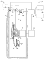
图1为可使用根据本公开内容的教授内容构造的制动器控制系统的示例性电梯系统; 1 is an exemplary elevator system that may use a brake control system constructed in accordance with the teachings of this disclosure;
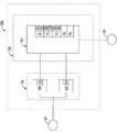
图2为示出根据本公开内容的教授内容的制动器控制系统的一个实施例的示意图; FIG. 2 is a schematic diagram illustrating one embodiment of a brake control system according to the teachings of the present disclosure;
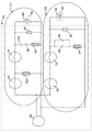
图3为用于在图2的制动器控制系统中使用的制动器控制装置的一个实施例;以及 FIG. 3 is one embodiment of a brake control device for use in the brake control system of FIG. 2; and
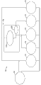
图4示出了图3的制动器控制装置的各种电气构件与电梯系统互连的一个实施例。 Figure 4 illustrates one embodiment of the interconnection of various electrical components of the brake control of Figure 3 with an elevator system.
尽管本公开内容许各种修改和备选构造,但其某些示例性实施例已经在附图中示出且将在下文详细地描述。然而,应理解的是,不旨在限于所公开的特定形式,而相反,旨在覆盖落入本公开内容的要旨和范围的所有的修改、备选构造和等同物。 While the present disclosure is susceptible to various modifications and alternative constructions, certain exemplary embodiments thereof have been shown in the drawings and will be described in detail below. It should be understood, however, that the intention is not to be limited to the particular forms disclosed, but on the contrary, the intention is to cover all modifications, alternative constructions, and equivalents falling within the spirit and scope of the disclosure.
具体实施方式 Detailed ways
现参照图1,以示意图方式示出了示例性的电梯系统20。将理解的是,图1中示出的电梯系统20的形式仅出于示范目的,且用以呈现用于通常的电梯系统的各种构件的背景。
Referring now to FIG. 1 , an
如图1中所示,电梯系统20可至少部分地存在于垂直地设在多层建筑物24内的井道22中。电梯系统的一些构件可存在于井道22外,例如,井道上方的机器房中。通常,井道22可为设在建筑物物24的中心部分内的中空竖井,其中如果建筑物具有足够的大小且包括多个电梯,则提供多个井道。轨道26和28可大致延伸井道22的长度。电梯轿厢30可滑动地安装在一对轨道26上(为了清楚起见,图1中仅示出了一个轨道26),且配重32可滑动地安装在一对轨道28上(为了清楚起见,图1中仅示出一个轨道28)。尽管图1中未详细描绘,但本领域中的普通技术人员将理解的是,轿厢30和配重32两者都可包括辊子装配件34、轴承等,以用于沿轨道26和28平稳移动。辊子装配件、轴承等还可以以稳固的方式可滑动地安装到轨道26和28。
As shown in FIG. 1 ,
为了移动轿厢30且因此移动装载在轿厢上的乘客和/或货物,包括电动马达36的机器(31)通常可设在井道22的顶部处或设在井道22上方的机器房中。电子控制器38可电联接到马达36,该电子控制器38继而又可电联接到设在各楼层上的多个操作者界面40以调用电梯轿厢30,以及设在各个轿厢30上的操作者界面42以允许其乘客规定轿厢30的方向。
In order to move the
安全链电路54以及电力供应部56还可电联接到电子控制器38。传动轴44可从马达36机械地延伸,该传动轴44继而又可操作地联接到牵引滑轮46,且还可延伸以操作地联接到制动设备52。在一些情况下,牵引滑轮46可为传动轴44的一部分。
受拉部件48可围绕滑轮46连续,该受拉部件48如圆形绳索或平坦带。受拉部件48继而又可以以任何适合的绳索布置来操作地联接到配重32和轿厢30。当然,这些构件的多个不同实施例或布置可能带有包括多个受拉部件48以及用于电梯系统20的马达和滑轮的各种布置的典型系统。
A
电梯系统20还可包括制动器控制系统58。在一些实施例,用于升起和降下电梯轿厢30的机器31可包括制动器控制系统58。如图2中所示,制动器控制系统58可电连接到电力供应部56,且机械地联接到电梯系统20的马达36。制动器控制系统58可包括电连接到制动器控制装置60的制动设备52。
The
制动设备52可包括至少一个制动器。在示例性实施例中,制动设备52可包括第一制动器(如,服务制动器66)和第二制动器(如,紧急制动器62)。第一制动器可为与第二制动器分离的单元,或第一制动器和第二制动器可为单个制动器单元的构件。紧急制动器62可具有磁性紧急制动器线圈64,且服务制动器66可具有磁性服务制动器线圈68。在激励时,制动器线圈64、68引起制动器62、66解除接合,从而不施加制动力来减慢或停止电梯轿厢30。在制动器线圈64、68没有激励(或未充分激励)时,制动器62、66接合,且制动力被施加至电梯轿厢(这还可被称为"使制动器落下")。
The braking device 52 may comprise at least one brake. In an exemplary embodiment, braking apparatus 52 may include a first brake (eg, service brake 66 ) and a second brake (eg, emergency brake 62 ). The first brake may be a separate unit from the second brake, or the first brake and the second brake may be members of a single brake unit. The
制动器控制装置60可联接到制动设备52的制动器线圈64、68,且在某些操作情况期间可选择性地控制线圈64、68中的一者或两者内的储存能量的衰减。在实施例中,制动器控制装置60可为电子控制器38的一部分。在其它实施例中,制动器控制装置60可与电子控制器38相分离或并入电梯系统20中的其它构件中。在实施例中,制动器控制装置60可控制各个制动器线圈64、68内的储存能量的衰减,从而可相对快地接合制动器62、66中的一者,且另一个制动器的接合可通过在其相关的制动器线圈内的储存能量的自然衰减而延迟。紧急制动器62和服务制动器66的应用的定序可减小施加至传动轴44(图1)的初始迟滞力,该初始迟滞力导致电梯轿厢30的较低的减速速率。在其期间选择性地控制可使用的一个或两个线圈内的储存能量的衰减的电梯系统的操作状态包括,例如,电力损失、无意轿厢移动、上升轿厢超速等。
The
制动器控制装置60可包括具有多个接触件的制动拾取件(brake pick)70、具有多个接触件的电力监测继电器72、具有多个接触件的超速继电器74、无意轿厢移动(UCM)继电器76和安全链继电器78。制动拾取件70用于闭合开关80和82,以在电梯运转开始时激励制动器线圈64和68且在电梯运转结束时断开开关80和82。在实施例中,电力监测继电器72可监测交流(AC)电力。在其它实施例中,电力监测继电器72可监测直流(DC)电力,或DC和AC电力。如下文进一步论述的那样,制动器控制装置60还可包括制动器电源、多个二极管和多个缓冲器。缓冲器可用于本文论述的制动器控制装置60,以在电流突然中断时防止对制动器控制装置元件的损坏。
The
现转向图3,公开了示例性的制动器控制装置60。制动器控制装置60可通过紧急制动器线圈64而电连接到紧急制动器62,且通过服务制动器线圈68而电连接到服务制动器66。第一制动开关80可连接到UCM继电器76。如图3中所示,制动器控制装置60可包括第一二极管84,该第一二极管84可通过超速继电器74的第一接触件86和第一电力监测继电器72的主接触件88而与紧急制动器线圈64并联。超速继电器74用于在超速事件期间断开开关86,以切断二极管84,以防止紧急制动器线圈64中的电流循环。第一缓冲器90还可与紧急制动器线圈64并联。UCM继电器76可连接到紧急制动器线圈64。以上所描述的制动器控制装置60的部分和紧急制动器线圈64可共同被称为"紧急制动器电路"92。在实施例中,紧急制动器电路92可接收来自制动器电源94的电力,该制动器电源94可为制动器控制装置60的一部分。
Turning now to FIG. 3 , an exemplary
如图3中进一步所示,第二制动开关82可连接到安全链继电器78。安全链继电器78可连接到服务制动器线圈68。第二二极管96可通过超速继电器74的第二接触件98和电力监测继电器72的副接触件100而与服务制动器线圈68并联。缓冲器91还可与服务制动器线圈68并联。第三二极管102可连接到安全链继电器78。以上所描述的制动器控制装置60的部分和服务制动器线圈68可共同被称为"服务制动器电路"104。服务制动器电路104可接收来自制动器电源94的电力。
As further shown in FIG. 3 , a
如图4中示意性地示出,电力供应部56可激励安全链54和电力继电器72。应理解的是,电力供应部56可激励电梯系统20内的其它构件,例如但不限于电子控制器38和操作者界面40、42。此外,电力供应部56可取决于所激励的构件的电力需要而提供AC电源和/或DC电源。此外,电梯系统20可结合一个以上的电力供应部,以激励系统20内的各种构件。例如,在实施例中,可使用单独的制动器电源94,以向紧急制动器电路92和服务制动器电路104提供电力。
As shown schematically in FIG. 4 , the
安全链54可包括电连接在一起的调节器106和各种电气保护装置(EPDs)108。调节器106监测轿厢30的速度。在备选实施例中,除了调节器106以外的装置也可监测轿厢30的速度,包括超速。EPDs108可监测各种电梯系统20的构件安全状态。调节器106和EPDs 108可以以串联电路连接在一起。如果调节器106或EPDs108中的一个没有闭合(接通电路),则安全链54可为"断开的"。通常,当安全链54断开时,使电梯轿厢30停止或保持停止。当轿厢30的速度超过阈值时,此类断开状态可由调节器106触发。当由EPD108探测到不安全情况时,也可触发断开状态。如图4中所示,超速继电器74、UCM继电器76和安全链继电器78可电连接到安全链54。在一些实施例中,这些元件可为安全链54的一部分。此外,制动拾取件70可由电力供应部56激励。
The
如图3-4中所示,在电梯系统20的正常操作期间,第一制动开关80和第二制动开关82可为闭合的,安全链继电器78可为闭合的,UCM继电器76可为闭合的,且可激励超速继电器74和电力监测继电器72两者。当激励时,在紧急制动器电路92中,第一超速继电器接触件86可为闭合的,且主电力监测继电器接触件88可为断开的。在服务制动器电路104中,第二超速继电器接触件98可为断开的,且副电力监测继电器接触件100可为闭合的。在该实施例中,由于第二超速继电器接触件98断开,因而第二二极管96大致与服务制动器线圈68切断。
As shown in FIGS. 3-4, during normal operation of the
当接收到信号以在楼层处停止电梯轿厢30来供乘客上下时,马达起停止电梯的作用。服务制动器66和紧急制动器62在停止期间可用于将电梯轿厢30保持在适当的位置。因此,第一制动开关80和第二制动开关82可断开。然而,在图3中示出的实施例中,从服务制动器线圈68流动的剩余电流的一些可继续循环经过第三二极管102和安全链继电器78,返回经过服务制动器线圈68。来自紧急制动器线圈64的一些剩余电流可继续循环经过第一二极管84和第一超速继电器接触件86,返回到紧急制动器线圈64。由于此类电路对来自制动器线圈64、68的剩余电流提供了低阻抗电流通路,因而流经制动器线圈64、68的电流相对慢地衰减。当由制动开关80、82移除电力时,制动器线圈64、68两者中的该缓慢衰减延迟了服务制动器66和紧急制动器62两者的应用。当电流耗散超过阈值时,其不再可激励线圈,且相应的制动器将被接合(被落下)。在实施例中,该延迟可在大约150毫秒到大约600毫秒的范围内。
When a signal is received to stop the
如本领域中已知的那样,当移动的电梯轿厢30的速度超过限定的阈值时,发生轿厢在任一方向上的超速。在此类超速的事件中,调节器106断开。在图3至图4中示出的实施例中,调节器106的断开中断(断开)安全链54,且引起UCM继电器76、超速继电器74和安全链继电器78中的各个都断开。虽然调节器106断开,但电力监测继电器72可保持激励。
As is known in the art, overspeeding of the car in either direction occurs when the speed of the moving
在超速事件期间,第一超速继电器接触件86和主电力监测继电器接触件88两者可在紧急制动器电路92中断开。这可导致第一二极管84与紧急制动器线圈64切断。因此,紧急制动器线圈64中的电流相对快地耗散,且一旦电流变得太弱以致于不能继续激励紧急制动器线圈64,则接合紧急制动器62。
During an overspeed event, both the first
在图3中示出的实施例中,断开安全链继电器78使第三二极管102与服务制动器线圈68切断。在服务制动器电路104中,第二超速继电器接触件98和副电力监测继电器接触件100两者都闭合,因而第二二极管96与服务制动器线圈68并联。由于该布置对剩余电流提供了低阻抗循环通路,因而来自服务制动器线圈68的一些剩余电流可继续循环经过第二二极管96、第二超速继电器接触件98和副电力监测继电器接触件100,返回到服务制动器线圈68。这减慢了服务制动器线圈68中的电流衰减,因此延迟了服务制动器66的应用。在实施例中,延迟可在大约150毫秒到大约600毫秒的范围内。一旦剩余电流变得太弱以致于不能继续激励服务制动器线圈68,则接合服务制动器66,且制动器中的弹簧克服由激励的线圈创造的力并应用制动力。相反,紧急制动器线圈64的剩余电流不具有低阻抗的循环通路,且快速地衰减,因此引起紧急制动器62通常比服务制动器落下得更快。
In the embodiment shown in FIG. 3 , opening the
如本领域中已知的那样,有时,电梯轿厢30在操作期间可经历无意轿厢移动(UCM)。此类UCM事件的示例为当轿厢(30)处于楼梯平台处且门开启或未锁的同时发生轿厢(30)的移动。在操作期间感测到UCM的情况下,UCM继电器76和安全链54两者断开。在图3至图4中示出的实施例中,断开安全链54还断开了安全链继电器78,因此使第三二极管102与服务制动器线圈68切断。如图3-4中所示,超速继电器74和电力监测继电器72两者都被激励。当激励时,在紧急制动器电路92中,第一超速继电器接触件86可闭合,且主电力监测继电器接触件88可断开。在服务制动器电路104中,第二超速继电器接触件98可断开,且副电力监测继电器接触件100可闭合。由于第二超速继电器接触件98断开,因而第二二极管96与服务制动器线圈68切断。第一二极管84通过第一超速继电器接触件86而与紧急制动器线圈64并联联结。因此,在UCM事件期间,由于剩余的服务制动器线圈68电流不具有低阻抗循环通路,因而服务制动器66无延迟地落下。相反,紧急制动器62的应用(或落下)利用再循环经过紧急制动器线圈64的剩余电流来延迟。一旦剩余电流变得太弱以致于不能激励紧急制动器线圈64,则紧急制动器62将被接合。在实施例中,延迟可在大约150毫秒到大约600毫秒的范围内。
As is known in the art, at times,
如图3-4中所示,在电梯损失电力的事件中,超速继电器74和电力监测继电器72两者以及UCM继电器76和安全链继电器78都可解除激励。在此情况下,在紧急制动器电路92中,第一超速继电器接触件86可断开,且主电力监测继电器接触件88可闭合。在服务制动器电路104中,第二超速继电器接触件98可闭合,且副电力监测继电器接触件100可断开。
As shown in Figures 3-4, in the event of an elevator losing power, both the
在图3的实施例中,第一二极管84通过主电力监测继电器接触件88而与紧急制动器线圈64并联联结。另一方面,由于副电力监测继电器接触件100断开,因而第二二极管96与服务制动器线圈68大致切断。此外,第三二极管102因安全链继电器78而与服务制动器线圈68切断。由于服务制动器66电流不具有低阻抗循环通路,因而服务制动器线圈68中的电流将相对快地耗散,从而允许相对快地接合服务制动器66。紧急制动器62的应用将通过剩余的紧急制动器线圈电流的一些再循环经过主电力监测继电器接触件88返回到紧急制动器线圈64从而延迟。一旦剩余电流变得太弱以致于不能激励紧急制动器线圈64,则紧急制动器62将被接合。在实施例中,该延迟可在大约150毫秒到大约600毫秒的范围内。
In the embodiment of FIG. 3 , the
行业应用 Industry application
根据前述内容,可看到的是,本公开内容阐明了带有新颖制动系统的电梯,该制动系统当电梯轿厢在紧急停止或电力损失的事件期间被制动器停止时减小对乘客造成不适。电梯持续地用于将乘客从一层运输到另一层,从而产生了频繁的停止。甚至在紧急事件中,本公开内容的制动系统也减小了对乘客造成的不适。当电梯经历电力损失或故障(如,超速或UCM事件)时,可能发生紧急状况。在紧急事件中,制动装置可确保电梯产生平稳的停止。 From the foregoing, it can be seen that the present disclosure sets forth an elevator with a novel braking system that reduces the discomfort. Elevators are continuously used to transport passengers from one floor to another, resulting in frequent stops. Even in an emergency, the braking system of the present disclosure reduces discomfort to passengers. Emergency situations may occur when an elevator experiences a power loss or failure (eg, overspeed or UCM event). In an emergency, the braking device ensures that the elevator comes to a smooth stop.
电梯系统可包括轿厢、包括可在断开位置与闭合位置之间移动的调节器开关的安全链、具有第一磁性制动器线圈的第一制动器、具有第二磁性制动器线圈的第二制动器、以及具有制动器电源的制动器控制装置。第一制动器可在解除接合位置与接合位置之间移动。第二制动器可在解除接合位置与接合位置之间移动。制动器控制装置可电连接到第一制动器和第二制动器以及调节器开关,且可构造成利用来自相应制动器线圈的剩余电流而选择性地延迟第一制动器和第二制动器向接合位置的移动。选择性地定序延迟制动器的接合至少可使电梯轿厢的停止对乘客变得柔和。 The elevator system may include a car, a safety chain including a regulator switch movable between an open position and a closed position, a first brake having a first magnetic brake coil, a second brake having a second magnetic brake coil, and Brake control with brake power supply. The first brake is movable between a disengaged position and an engaged position. The second brake is movable between a disengaged position and an engaged position. A brake control device may be electrically connected to the first and second brakes and the regulator switch, and may be configured to selectively delay movement of the first and second brakes to the engaged position using residual current from the respective brake coils. Selectively sequencing the delayed engagement of the brakes at least makes stopping of the elevator car softer for passengers.
尽管已经阐明了仅某些实施例,但备选和修改将从以上描述中对本领域中的技术人员变得明显。这些和其它备选被认为是等同物,且在本公开内容的要旨和范围内。 While only certain embodiments have been set forth, alternatives and modifications will become apparent to those skilled in the art from the above description. These and other alternatives are considered equivalents and within the spirit and scope of this disclosure.
Claims (24)
Applications Claiming Priority (1)
| Application Number | Priority Date | Filing Date | Title |
|---|---|---|---|
| PCT/US2011/023769 WO2012105986A1 (en) | 2011-02-04 | 2011-02-04 | Stop sequencing for braking device |
Publications (2)
| Publication Number | Publication Date |
|---|---|
| CN103328362A true CN103328362A (en) | 2013-09-25 |
| CN103328362B CN103328362B (en) | 2015-11-25 |
Family
ID=46603026
Family Applications (1)
| Application Number | Title | Priority Date | Filing Date |
|---|---|---|---|
| CN201180066730.6A Active CN103328362B (en) | 2011-02-04 | 2011-02-04 | For the stopping sequencing of brake equipment |
Country Status (5)
| Country | Link |
|---|---|
| US (1) | US9457987B2 (en) |
| EP (1) | EP2670695B1 (en) |
| JP (1) | JP5909505B2 (en) |
| CN (1) | CN103328362B (en) |
| WO (1) | WO2012105986A1 (en) |
Cited By (5)
| Publication number | Priority date | Publication date | Assignee | Title |
|---|---|---|---|---|
| CN106573751A (en) * | 2014-08-07 | 2017-04-19 | 因温特奥股份公司 | Elevator system, brake system for an elevator system and method for controlling a brake system of an elevator system |
| CN107000961A (en) * | 2014-11-24 | 2017-08-01 | 奥的斯电梯公司 | Electromagnetic braking system |
| CN108290705A (en) * | 2015-11-02 | 2018-07-17 | 因温特奥股份公司 | Elevator is staggeredly braked |
| CN110621606A (en) * | 2017-05-23 | 2019-12-27 | 三菱电机株式会社 | Brake release device for elevator |
| US20210163262A1 (en) * | 2018-10-03 | 2021-06-03 | Mitsubishi Electric Corporation | Elevator control device |
Families Citing this family (15)
| Publication number | Priority date | Publication date | Assignee | Title |
|---|---|---|---|---|
| CN102892698B (en) * | 2010-05-21 | 2015-05-06 | 奥的斯电梯公司 | Braking device for elevator, elevator and method for controlled stopping of elevator |
| FI122393B (en) * | 2010-10-11 | 2011-12-30 | Kone Corp | Method in the event of an elevator emergency stop and lift safety arrangement |
| FI123506B (en) * | 2012-05-31 | 2013-06-14 | Kone Corp | Elevator control and elevator safety arrangement |
| US9828211B2 (en) * | 2012-06-20 | 2017-11-28 | Otis Elevator Company | Actively damping vertical oscillations of an elevator car |
| CN102795524B (en) * | 2012-07-27 | 2014-07-23 | 石家庄五龙制动器股份有限公司 | ABS brake control circuit of elevator brake system |
| WO2015038116A1 (en) * | 2013-09-11 | 2015-03-19 | Otis Elevator Company | Braking device for braking a hoisted object relative to a guide member |
| FI124903B (en) * | 2013-11-01 | 2015-03-13 | Kone Corp | Elevator and method for utilizing the elevator control system for monitoring the load in the basket and / or for determining a load situation |
| US10479645B2 (en) | 2015-06-29 | 2019-11-19 | Otis Elevator Company | Electromagnetic brake system for elevator application |
| US10450162B2 (en) | 2015-06-29 | 2019-10-22 | Otis Elevator Company | Electromagnetic brake control circuitry for elevator application |
| US10442659B2 (en) * | 2015-06-29 | 2019-10-15 | Otis Elevator Company | Electromagnetic brake system for elevator application |
| CN107922147B (en) * | 2015-08-12 | 2019-11-19 | 因温特奥股份公司 | Anti-lock braking device for an elevator and method for controlling the same |
| EP3153443B1 (en) * | 2015-10-08 | 2021-09-08 | KONE Corporation | A method and an arrangement for controlling an elevator machinery brake |
| US10919730B2 (en) | 2016-03-18 | 2021-02-16 | Otis Elevator Company | Management of mutiple coil brake for elevator system |
| US11040848B2 (en) | 2018-03-27 | 2021-06-22 | Otis Elevator Company | Elevator machine brake delay control |
| EP4008664B1 (en) * | 2020-12-04 | 2024-10-23 | Otis Elevator Company | Method of preventing gravity jump at emergency stop in elevator systems |
Citations (4)
| Publication number | Priority date | Publication date | Assignee | Title |
|---|---|---|---|---|
| JP2001146366A (en) * | 1999-11-19 | 2001-05-29 | Mitsubishi Electric Corp | Elevator braking system |
| CN100526190C (en) * | 2005-03-16 | 2009-08-12 | 株式会社日立制作所 | Arrester control device for elevator |
| CN101903276A (en) * | 2007-12-10 | 2010-12-01 | 奥蒂斯电梯公司 | Elevator braking apparatus including permanent magnets biased to apply braking force |
| CN101903279A (en) * | 2007-12-21 | 2010-12-01 | 因温特奥股份公司 | Elevator with two elevator cars and common counterweight |
Family Cites Families (38)
| Publication number | Priority date | Publication date | Assignee | Title |
|---|---|---|---|---|
| US4116306A (en) * | 1977-04-29 | 1978-09-26 | Elevator Industries | Elevator car generator-motor-brake control unit apparatus and method |
| IT208095Z2 (en) | 1986-05-07 | 1988-03-31 | Gmv Service S R L | BRAKING DEVICE FOR LIFTING VEHICLES, SUCH AS LIFTS AND LIFTS. |
| JPH0697875B2 (en) | 1987-05-20 | 1994-11-30 | 日本オ−チス・エレベ−タ株式会社 | Inverter for driving elevator |
| JPH0764493B2 (en) * | 1988-06-27 | 1995-07-12 | 三菱電機株式会社 | Elevator control equipment |
| JPH04286587A (en) | 1991-03-14 | 1992-10-12 | Mitsubishi Electric Corp | Linear motor type elevator control device |
| JPH05201678A (en) * | 1992-01-22 | 1993-08-10 | Mitsubishi Electric Corp | Passenger conveyor control device |
| US5327055A (en) * | 1993-03-08 | 1994-07-05 | International Business Machines Corporation | Mechanical brake hold circuit for an electric motor |
| JPH06286950A (en) * | 1993-04-02 | 1994-10-11 | Mitsubishi Electric Corp | Linear motor drive elevator controller |
| JPH07101645A (en) * | 1993-10-05 | 1995-04-18 | Hitachi Building Syst Eng & Service Co Ltd | Elevator emergency stop device |
| JPH07157211A (en) * | 1993-12-03 | 1995-06-20 | Mitsubishi Electric Corp | Elevator brake equipment |
| FI97718C (en) | 1995-03-24 | 1997-02-10 | Kone Oy | Elevator motor emergency drive |
| US5893432A (en) | 1996-12-31 | 1999-04-13 | Inventio Ag | Controlled emergency stop apparatus for elevators |
| JP4439074B2 (en) | 2000-03-29 | 2010-03-24 | 三菱電機株式会社 | Elevator emergency stop device |
| US6802395B1 (en) * | 2003-03-28 | 2004-10-12 | Kone Corporation | System for control and deceleration of elevator during emergency braking |
| JP2007046129A (en) | 2005-08-11 | 2007-02-22 | Sanyo Electric Co Ltd | Electrode for electrolysis, and method for producing electrode for electrolysis |
| EP1918239B1 (en) | 2005-08-25 | 2016-09-21 | Mitsubishi Denki Kabushiki Kaisha | Elevator device |
| EP1939125B1 (en) * | 2005-10-17 | 2015-03-11 | Mitsubishi Denki Kabushiki Kaisha | Elevator device |
| FI118124B (en) * | 2006-01-17 | 2007-07-13 | Kone Corp | Gejdbroms |
| JP5037139B2 (en) * | 2006-02-01 | 2012-09-26 | 三菱電機株式会社 | Elevator equipment |
| EP2765107B1 (en) | 2006-03-17 | 2015-03-11 | Mitsubishi Electric Corporation | Elevator apparatus |
| US7770698B2 (en) | 2006-03-17 | 2010-08-10 | Mitsubishi Electric Corporation | Elevator apparatus |
| KR100931430B1 (en) * | 2006-03-20 | 2009-12-11 | 미쓰비시덴키 가부시키가이샤 | Elevator device |
| MY151628A (en) | 2006-05-29 | 2014-06-30 | Inventio Ag | Lift facility with a braking device and method for braking a lift facility |
| CN101268003B (en) | 2006-07-27 | 2010-08-18 | 三菱电机株式会社 | Elevator device |
| JP4821548B2 (en) | 2006-10-02 | 2011-11-24 | コニカミノルタホールディングス株式会社 | Image processing apparatus, image processing apparatus control method, and image processing apparatus control program |
| JP5188699B2 (en) * | 2006-11-08 | 2013-04-24 | 株式会社日立製作所 | Brake control device for elevator |
| KR101181205B1 (en) * | 2007-01-23 | 2012-09-18 | 미쓰비시덴키 가부시키가이샤 | Elevator apparatus |
| FI120828B (en) * | 2007-02-21 | 2010-03-31 | Kone Corp | Electronic motion limiter and procedure for controlling electronic motion limiter |
| EP2147883B1 (en) | 2007-05-24 | 2017-11-29 | Mitsubishi Electric Corporation | Elevator apparatus |
| EP2011759A1 (en) | 2007-07-03 | 2009-01-07 | Inventio Ag | Device and method for operating a lift |
| ES2343608B1 (en) | 2007-08-03 | 2011-06-16 | Orona, S.Coop | PROCEDURE AND DEVICE FOR ACTION IN EMERGENCY SITUATION IN LIFTING DEVICES. |
| JP5339705B2 (en) | 2007-10-05 | 2013-11-13 | 株式会社日立製作所 | Elevator safe stop method and safe stop system |
| EP2303747B1 (en) | 2008-06-17 | 2013-04-10 | Otis Elevator Company | Safe control of a brake using low power control devices |
| RU2484003C2 (en) | 2008-07-25 | 2013-06-10 | Отис Элевэйтор Компани | Method of lift operation in emergency mode |
| CN102414110A (en) * | 2009-05-01 | 2012-04-11 | 三菱电机株式会社 | Elevator device |
| FI20090335L (en) * | 2009-09-16 | 2011-03-17 | Kone Corp | Method and arrangement for preventing uncontrolled movement of an elevator car |
| FI122393B (en) * | 2010-10-11 | 2011-12-30 | Kone Corp | Method in the event of an elevator emergency stop and lift safety arrangement |
| BR112013021840B1 (en) * | 2011-08-16 | 2020-08-25 | Inventio Ag | method and device in an emergency to apply an elevator brake to an elevator installation |
-
2011
- 2011-02-04 WO PCT/US2011/023769 patent/WO2012105986A1/en not_active Ceased
- 2011-02-04 CN CN201180066730.6A patent/CN103328362B/en active Active
- 2011-02-04 EP EP11857863.2A patent/EP2670695B1/en active Active
- 2011-02-04 US US13/983,234 patent/US9457987B2/en active Active
- 2011-02-04 JP JP2013552508A patent/JP5909505B2/en active Active
Patent Citations (4)
| Publication number | Priority date | Publication date | Assignee | Title |
|---|---|---|---|---|
| JP2001146366A (en) * | 1999-11-19 | 2001-05-29 | Mitsubishi Electric Corp | Elevator braking system |
| CN100526190C (en) * | 2005-03-16 | 2009-08-12 | 株式会社日立制作所 | Arrester control device for elevator |
| CN101903276A (en) * | 2007-12-10 | 2010-12-01 | 奥蒂斯电梯公司 | Elevator braking apparatus including permanent magnets biased to apply braking force |
| CN101903279A (en) * | 2007-12-21 | 2010-12-01 | 因温特奥股份公司 | Elevator with two elevator cars and common counterweight |
Cited By (10)
| Publication number | Priority date | Publication date | Assignee | Title |
|---|---|---|---|---|
| CN106573751A (en) * | 2014-08-07 | 2017-04-19 | 因温特奥股份公司 | Elevator system, brake system for an elevator system and method for controlling a brake system of an elevator system |
| CN107000961A (en) * | 2014-11-24 | 2017-08-01 | 奥的斯电梯公司 | Electromagnetic braking system |
| US10745239B2 (en) | 2014-11-24 | 2020-08-18 | Otis Elevator Company | Electromagnetic brake system for an elevator with variable rate of engagement |
| US11897725B2 (en) | 2014-11-24 | 2024-02-13 | Otis Elevator Company | Adjustment of drop rate of elevator car with electromagnetic brake system |
| CN108290705A (en) * | 2015-11-02 | 2018-07-17 | 因温特奥股份公司 | Elevator is staggeredly braked |
| US10494224B2 (en) | 2015-11-02 | 2019-12-03 | Inventio Ag | Staggered braking of an elevator |
| CN110621606A (en) * | 2017-05-23 | 2019-12-27 | 三菱电机株式会社 | Brake release device for elevator |
| CN110621606B (en) * | 2017-05-23 | 2021-03-23 | 三菱电机株式会社 | Brake release device for elevator |
| US20210163262A1 (en) * | 2018-10-03 | 2021-06-03 | Mitsubishi Electric Corporation | Elevator control device |
| US12486143B2 (en) * | 2018-10-03 | 2025-12-02 | Mitsubishi Electric Corporation | Elevator control device |
Also Published As
| Publication number | Publication date |
|---|---|
| WO2012105986A1 (en) | 2012-08-09 |
| EP2670695A4 (en) | 2017-07-05 |
| EP2670695A1 (en) | 2013-12-11 |
| CN103328362B (en) | 2015-11-25 |
| EP2670695B1 (en) | 2022-09-07 |
| JP5909505B2 (en) | 2016-04-26 |
| US9457987B2 (en) | 2016-10-04 |
| US20130313052A1 (en) | 2013-11-28 |
| JP2014504579A (en) | 2014-02-24 |
| HK1189564A1 (en) | 2014-06-13 |
Similar Documents
| Publication | Publication Date | Title |
|---|---|---|
| CN103328362B (en) | For the stopping sequencing of brake equipment | |
| CN102892698B (en) | Braking device for elevator, elevator and method for controlled stopping of elevator | |
| KR101229002B1 (en) | Safe control of a brake using low power control devices | |
| CN102036898B (en) | Elevator apparatus and operating method thereof | |
| CN107207199B (en) | Rescue device and elevator | |
| US9688511B2 (en) | Brake | |
| CN103249662B (en) | Method relating to an emergency stop situation of an elevator, and safety device for an elevator | |
| CN110657178A (en) | Method, software program and brake system for diagnosing and/or maintaining a brake | |
| CN107108158B (en) | Rescue device and elevator | |
| CN103313927B (en) | Backup circuit for electricity supply, elevator system, and method | |
| CN1886320B (en) | elevator safety device | |
| CN114426236A (en) | Emergency stop device and elevator | |
| CN107000961A (en) | Electromagnetic braking system | |
| CN1993289B (en) | Traction device for elevator | |
| HK1189564B (en) | Stop sequencing for braking device | |
| CN108290705A (en) | Elevator is staggeredly braked | |
| JP2025104878A (en) | Elevator safety system and elevator | |
| HK40020359A (en) | Method for diagnosis and/or maintenance of a brake of a transportation system, computer readable medium, and brake apparatus | |
| HK1157722B (en) | Safe control of a brake using low power control devices | |
| HK1208896B (en) | Brake | |
| HK1244772A1 (en) | A rescue apparatus and an elevator | |
| HK1240563A1 (en) | A rescue apparatus and an elevator |
Legal Events
| Date | Code | Title | Description |
|---|---|---|---|
| C06 | Publication | ||
| PB01 | Publication | ||
| C10 | Entry into substantive examination | ||
| SE01 | Entry into force of request for substantive examination | ||
| REG | Reference to a national code |
Ref country code: HK Ref legal event code: DE Ref document number: 1189564 Country of ref document: HK |
|
| C14 | Grant of patent or utility model | ||
| GR01 | Patent grant | ||
| REG | Reference to a national code |
Ref country code: HK Ref legal event code: GR Ref document number: 1189564 Country of ref document: HK |