CN103277366A - Numerical control double-arm double-cylinder stretch bender hydraulic oil temperature adjustment device - Google Patents
Numerical control double-arm double-cylinder stretch bender hydraulic oil temperature adjustment device Download PDFInfo
- Publication number
- CN103277366A CN103277366A CN 201310190954 CN201310190954A CN103277366A CN 103277366 A CN103277366 A CN 103277366A CN 201310190954 CN201310190954 CN 201310190954 CN 201310190954 A CN201310190954 A CN 201310190954A CN 103277366 A CN103277366 A CN 103277366A
- Authority
- CN
- China
- Prior art keywords
- hydraulic oil
- double
- numerical control
- oil temperature
- adjustment device
- Prior art date
- Legal status (The legal status is an assumption and is not a legal conclusion. Google has not performed a legal analysis and makes no representation as to the accuracy of the status listed.)
- Pending
Links
Images


Abstract
The invention provides a numerical control double-arm double-cylinder stretch bender hydraulic oil temperature adjustment device, and relates to the technical field of numerical control double-arm double-cylinder stretch benders manufacturing. The numerical control double-arm double-cylinder stretch bender hydraulic oil temperature adjustment device comprises a hydraulic cylinder (1), a circulating water pipe (2), a water inlet end (3), a water outlet end (4), a temperature sensor (5) and various servo valves. The circulating water pipe (2) is evenly connected outside the outer wall of the hydraulic cylinder (1) in a winding mode; the water inlet end (3) of the circulating water pipe (2) is arranged on the upper portion of one side of the hydraulic cylinder (1); the water outlet end (4) of the circulating water pipe (2) is arranged at the bottom of one side the hydraulic cylinder (1). The numerical control double-arm double-cylinder stretch bender hydraulic oil temperature adjustment device further comprises a fan shell (5) and fans (6). The fan shell (5) is arranged outside the hydraulic cylinder (1) and the circulating water pipe (2); the fans (6) are arranged on the periphery of the fan shell (5); the water inlet end (3) and the water outlet end (4) penetrate through the fan shell (5). When being too low in temperature, hydraulic oil can be heated by the numerical control double-arm double-cylinder stretch bender hydraulic oil temperature adjustment device, and can be cooled by the numerical control double-arm double-cylinder stretch bender hydraulic oil temperature adjustment device when being too high in temperature, the numerical control double-arm double-cylinder stretch bender hydraulic oil temperature adjustment device can keep the temperature of the hydraulic oil in an oil tank constant and ensure that a mother machine stably works, and is simple in structure, reasonable in design and easy to maintain.
Description
Technical field
The present invention relates to numerical control both arms twin-tub stretch benders manufacturing technology field, be specifically related to a kind of numerical control both arms twin-tub stretch benders hydraulic oil temperature controlling device.
Background technique
The temperature of hydraulic oil is generally controlled the scope about 30 ℃~50 ℃ in the hydraulic transmission, the highest should be above 60 ℃.If hydraulic fluid temperature is too high or low excessively, hydraulic system will produce harmful effect, and work is affected.After the oil temperature rise, the viscosity of oil product reduces, and the cohesive force of fluid reduces, and leakage increases, and machine run speed instability is easy to generate and creeps; After the oil temperature rise, hydraulic system pressure descends, and the stability of a system is affected, and has reduced operating accuracy, influences the equipment proper functioning; After the oil temperature rise, the lubricant film attenuation of relative motion surface, the hydraulic element expanded by heating has increased mechanical wear, and the pump valve class component increases wearing and tearing, even is stuck.
In order to reduce hydraulic oil temperature, dispose cooling system in the present hydraulic system, this cooling system structure complexity, volume is bigger, is not easy to maintaining.If it is low that hydraulic oil temperature is spent, then need start preheating earlier, reduce working efficiency, increase the wearing and tearing of machine.
Summary of the invention
The purpose of this invention is to provide a kind of numerical control both arms twin-tub stretch benders hydraulic oil temperature controlling device, it is crossed at hydraulic oil temperature and can heat it when low, can be to its cooling of lowering the temperature when hydraulic oil temperature is too high, and simple in structure, reasonable in design, be easy to maintaining.
In order to solve the existing problem of background technique, the present invention has adopted following technological scheme:
Numerical control both arms twin-tub stretch benders hydraulic oil temperature controlling device of the present invention comprises hydraulic jack 1, circulating pipe 2, feed-water end 3, waterexit end 4, temperature transducer and servovalve, circulating pipe 2 even solderless wrapped connections are in hydraulic jack 1 outer wall outside, and the feed-water end 3 of circulating pipe 2 is arranged at a upper lateral part of hydraulic jack 1, and the waterexit end 4 of circulating pipe 2 is arranged at a side bottom of hydraulic jack 1.
Its principle is: hydraulic oil temperature is crossed when hanging down, can in circulating pipe 2, feed hot water it is heated, when hydraulic oil temperature is too high, can in circulating pipe 2, feed cold water or frozen water to its cooling of lowering the temperature, 4 outflows reserve for other use energy saving to water after the heating through the waterexit end.Its temperature control is by temperature transducer and the control of various servovalve corresponding actions.
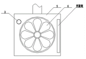
For when hydraulic oil temperature is too high, further strengthening radiating effect, also be provided with fan hub 5 and fan 6 in numerical control both arms twin-tub stretch benders hydraulic oil temperature controlling device of the present invention, fan hub 5 is arranged on the outside of hydraulic jack 1, circulating pipe 2, and be provided with fan 6 around the fan hub 5, feed-water end 3 and waterexit end 4 pass from fan hub 5.
Its principle is: when hydraulic oil temperature is too high, not only can in circulating pipe 2, feed cold water or frozen water to its cooling of lowering the temperature, can also open fan 6 and accelerate cooling, and good cooling results, assurance equipment can normal operation.
The beneficial effect of the invention: the present invention crosses at hydraulic oil temperature and can heat it when low, can be to its cooling of lowering the temperature when hydraulic oil temperature is too high, and simple in structure, reasonable in design, be easy to maintaining.When opening fan, heat radiation obtains promoting that cooling effect is strengthened, so cooling effect is better.
Description of drawings
Fig. 1 is the structural representation of a specific embodiment of the present invention,
Fig. 2 is the structural representation of another embodiment of the present invention,
Fig. 3 is the left view of Fig. 2,
Fig. 4 is the right elevation of Fig. 2.
In the drawings: 1 hydraulic jack; 2 circulating pipes; 3 feed-water ends; 4 waterexit ends; 5 fan hubs; 6 fans.
Embodiment
Embodiment one: with reference to Fig. 1, this embodiment is by the following technical solutions: it comprises hydraulic jack 1, circulating pipe 2, feed-water end 3 and waterexit end 4, circulating pipe 2 even solderless wrapped connections are in hydraulic jack 1 outer wall outside, and the feed-water end 3 of circulating pipe 2 is arranged at a upper lateral part of hydraulic jack 1, and the waterexit end 4 of circulating pipe 2 is arranged at a side bottom of hydraulic jack 1.
The principle of this embodiment is: hydraulic oil temperature is crossed when hanging down, can feed hot water in circulating pipe 2 heats it, when hydraulic oil temperature is too high, can in circulating pipe 2, feed cold water or frozen water to its cooling of lowering the temperature, 4 outflows reserve for other use energy saving to water after the heating through the waterexit end.Its temperature control is by temperature transducer and the control of various servovalve corresponding actions.
This embodiment is crossed at hydraulic oil temperature and can be heated it when low, can be to its cooling of lowering the temperature when hydraulic oil temperature is too high, and simple in structure, reasonable in design, be easy to maintaining.
Embodiment: with reference to Fig. 2-4, this embodiment is with the difference of embodiment one: it also comprises fan hub 5 and fan 6, fan hub 5 is arranged on the outside of hydraulic jack 1, circulating pipe 2, and be provided with fan 6 around the fan hub 5, feed-water end 3 and waterexit end 4 pass from fan hub 5.Other compositions are identical with embodiment one with annexation.
The principle of this embodiment is: when hydraulic oil temperature is too high, not only can in circulating pipe 2, feed cold water or frozen water to its cooling of lowering the temperature, can also open fan 6 and accelerate cooling, and good cooling results, assurance equipment can normal operation.
By reference to the accompanying drawings embodiments of the present invention have been done detailed explanation above, but the invention is not restricted to above-mentioned mode of execution, in the ken that affiliated technical field those of ordinary skill possesses, can also under the prerequisite that does not break away from aim of the present invention, make a variety of changes.
Claims (2)
1. numerical control both arms twin-tub stretch benders hydraulic oil temperature controlling device, it is characterized in that it comprises hydraulic jack (1), circulating pipe (2), feed-water end (3), waterexit end (4), temperature transducer and various servo electromagnetic valve, the even solderless wrapped connection of circulating pipe (2) is in hydraulic jack (1) outer wall outside, and the feed-water end (3) of circulating pipe (2) is arranged at a upper lateral part of hydraulic jack (1), the waterexit end (4) of circulating pipe (2) is arranged at a side bottom of hydraulic jack (1), adopt several servovalves, each oil hydraulic cylinder can keep constant different temperatures.
2. numerical control both arms twin-tub stretch benders hydraulic oil temperature controlling device according to claim 1, it is characterized in that it also comprises fan hub (5) and fan (6), fan hub (5) is arranged on the outside of hydraulic jack (1), circulating pipe (2), and be provided with fan (6) around the fan hub (5), feed-water end (3) and waterexit end (4) pass from fan hub (5).
Priority Applications (1)
| Application Number | Priority Date | Filing Date | Title |
|---|---|---|---|
| CN 201310190954 CN103277366A (en) | 2013-05-22 | 2013-05-22 | Numerical control double-arm double-cylinder stretch bender hydraulic oil temperature adjustment device |
Applications Claiming Priority (1)
| Application Number | Priority Date | Filing Date | Title |
|---|---|---|---|
| CN 201310190954 CN103277366A (en) | 2013-05-22 | 2013-05-22 | Numerical control double-arm double-cylinder stretch bender hydraulic oil temperature adjustment device |
Publications (1)
| Publication Number | Publication Date |
|---|---|
| CN103277366A true CN103277366A (en) | 2013-09-04 |
Family
ID=49059965
Family Applications (1)
| Application Number | Title | Priority Date | Filing Date |
|---|---|---|---|
| CN 201310190954 Pending CN103277366A (en) | 2013-05-22 | 2013-05-22 | Numerical control double-arm double-cylinder stretch bender hydraulic oil temperature adjustment device |
Country Status (1)
| Country | Link |
|---|---|
| CN (1) | CN103277366A (en) |
Cited By (4)
| Publication number | Priority date | Publication date | Assignee | Title |
|---|---|---|---|---|
| CN104006009A (en) * | 2013-12-13 | 2014-08-27 | 昆山洛博格机械技术咨询有限公司 | Multifunctional hydraulic station oil tank |
| CN104763709A (en) * | 2015-04-07 | 2015-07-08 | 中国直升机设计研究所 | Static-load holding actuator |
| CN105332159A (en) * | 2015-11-19 | 2016-02-17 | 长乐力天针纺有限公司 | Lubricating oil circulating cooling system for warp knitting machine |
| CN105442178A (en) * | 2016-02-16 | 2016-03-30 | 长乐力天针纺有限公司 | Warp knitting machine with cooling oil pump |
-
2013
- 2013-05-22 CN CN 201310190954 patent/CN103277366A/en active Pending
Cited By (4)
| Publication number | Priority date | Publication date | Assignee | Title |
|---|---|---|---|---|
| CN104006009A (en) * | 2013-12-13 | 2014-08-27 | 昆山洛博格机械技术咨询有限公司 | Multifunctional hydraulic station oil tank |
| CN104763709A (en) * | 2015-04-07 | 2015-07-08 | 中国直升机设计研究所 | Static-load holding actuator |
| CN105332159A (en) * | 2015-11-19 | 2016-02-17 | 长乐力天针纺有限公司 | Lubricating oil circulating cooling system for warp knitting machine |
| CN105442178A (en) * | 2016-02-16 | 2016-03-30 | 长乐力天针纺有限公司 | Warp knitting machine with cooling oil pump |
Similar Documents
| Publication | Publication Date | Title |
|---|---|---|
| CN103277366A (en) | Numerical control double-arm double-cylinder stretch bender hydraulic oil temperature adjustment device | |
| CN103835919B (en) | Residual neat recovering system | |
| CN202110453U (en) | Oil temperature control device for hydraulic system | |
| CN105313372A (en) | Superhigh-temperature energy-saving heating and cooling system | |
| CN203348226U (en) | Hydraulic oil temperature regulating device of numerical control double-arm double-cylinder stretch-bending machine | |
| CN102722190B (en) | Energy-saving oil temperature control system of machine tool | |
| CN203068774U (en) | Ultrahigh-temperature water temperature machine | |
| KR101723383B1 (en) | Temperature control system of oil tank | |
| CN103131830A (en) | Vacuum oil quenching furnace quenching cooling control system | |
| CN204254928U (en) | A kind of turbine exhaust steam waste heat recycling device | |
| CN203810733U (en) | Heat conduction oil furnace sealing circulating system | |
| CN207515032U (en) | A kind of heating system | |
| CN203453198U (en) | A hydraulic apparatus cooling device | |
| CN207178168U (en) | Water pump high-efficiency energy-saving control | |
| CN105351290A (en) | Hydraulic oil heat exchange device with circulating cooling function | |
| CN203430876U (en) | Hydraulic medium heating device of die casting machine | |
| CN207438900U (en) | A kind of Oil Guide heating unit of plasthetics processing | |
| CN203068801U (en) | Water temperature machine | |
| CN106762999A (en) | A kind of Full-automatic oil hydraulic refrigerator | |
| CN205370509U (en) | Microwave well head heater | |
| CN205064452U (en) | Loop formula hydraulic oil cooling device | |
| CN202301294U (en) | Hydraulic device for numerical control plate bending roll | |
| CN204150495U (en) | A kind of acrylic acid tank heat-insulation system | |
| CN203068800U (en) | 400-DEG C ultrahigh-temperature oil temperature machine | |
| CN203611405U (en) | Steam and water temperature control device of vulcanizing machine |
Legal Events
| Date | Code | Title | Description |
|---|---|---|---|
| C06 | Publication | ||
| PB01 | Publication | ||
| C10 | Entry into substantive examination | ||
| SE01 | Entry into force of request for substantive examination | ||
| C12 | Rejection of a patent application after its publication | ||
| RJ01 | Rejection of invention patent application after publication |
Application publication date: 20130904 |