CN103208696A - Socket connector and plug connector - Google Patents
Socket connector and plug connector Download PDFInfo
- Publication number
- CN103208696A CN103208696A CN 201210064976 CN201210064976A CN103208696A CN 103208696 A CN103208696 A CN 103208696A CN 201210064976 CN201210064976 CN 201210064976 CN 201210064976 A CN201210064976 A CN 201210064976A CN 103208696 A CN103208696 A CN 103208696A
- Authority
- CN
- China
- Prior art keywords
- wall
- roof
- hyoplastron
- diapire
- connector
- Prior art date
- Legal status (The legal status is an assumption and is not a legal conclusion. Google has not performed a legal analysis and makes no representation as to the accuracy of the status listed.)
- Pending
Links
Images


Landscapes
- Details Of Connecting Devices For Male And Female Coupling (AREA)
Abstract
A socket connector comprises a body, a plurality of conductive terminals fixed on the body and a shielding casing shielding the body. The shielding casing is provided with a containing space used for containing a plug connector, a top wall and a bottom wall located on the upper side and the lower side of the containing space respectively and two lateral walls connected between the top wall and the bottom wall. The body is provided with a base portion and a tongue plate extending frontward into the containing space from the base portion, and the conductive terminals are provided with contact portions extending to the tongue plate. The lateral walls of the shielding casing comprise a first lateral wall connected with the top wall and a second lateral wall connected with the first lateral wall and the bottom wall, and a 45-degree included angle is approximately formed between the second lateral wall and the bottom wall and between the first lateral wall and the bottom wall. The plug connector matched with the socket connector is further provided. The socket connector is simple in structure, capable of being connected with two types of plug connectors and is high in transmission speed.
Description
[technical field]
The present invention relates to a kind of socket connector and pin connector that improves transmitting high-frequency signal speed.
[background technology]
Usually link to each other in order to transmit signal each other with signal transmssion line between different electronic installations, and present signal transmssion line and electronic installation connect removably mostly by the joint on transmission line one end and the connector body on the electronic installation.
Electronic products such as digital camera, mobile phone, MP3 now the most universal signal transmission standard no more than USB (USB, Universal Serial Bus), the volume that the micro connector socket made from this specification and transmission line can reduce to take electronic products such as digital camera, mobile phone, MP3 makes things convenient for carrying and using of consumer.Micro universal universal serial bus (Micro USB) specification commonly used at present mostly is 2.0 versions, and theoretical transmission value can reach 480Mbps.
Yet the software document amount of electronic products such as digital camera, mobile phone, MP3 is constantly soaring at present, and prior USB 2.0 is not applied high flow capacity data transmission requirements gradually.China video electron trade association announced a new signal transmission standard on April 29th, 2009: DiiVA(DiiVA Digital Interface for Video and Audio), the signal transmission value can reach more than the 10Gbps, is enough to adapt to high flow capacity data transmission requirements.In order to use on small-sized electronic products such as digital camera, mobile phone, MP3, a kind of small-sized DiiVA interface is formulated in this association's plan, calls Micro Diiva in the following text.
On February 3rd, 2010, the Chinese utility model patent of bulletin disclosed a kind of relevant socket and plug for CN201397899Y number, but, socket in this patent is not compatible mutually with Micro USB interface, and portable product in the market still is mainstream configuration with the USB connector, the USB interface still is widely used in the various electronic products and does not have the anxiety of disappearance in a short time, and in response to the high flow capacity transmission requirements, following digital camera, mobile phone, electronic products such as MP3 also may be included Micro Diiva interface connector socket in, therefore, in the future digital camera soon, mobile phone, electronic products such as MP3 will possess the connector body of above-mentioned two kinds of specifications simultaneously.Yet the connector body that above-mentioned two kinds of interfaces are set simultaneously will certainly increase the size of electronic product, the development of incompatibility miniaturization of electronic products.Therefore, someone attempt with Micro USB and two kinds of connector bodies of Micro DiiVA with up and down side by side mode be arranged in the same housing, namely comprise two groups of terminals and two holders in this housing simultaneously, yet, this kind combination makes whole connector body thickness improve, and then make the thickness of electronic product that this connector body is set increase, also be unfavorable for the development of miniaturization of electronic products and be inconvenient to carry; As above two kinds of methods all need increase a connector body is set, and will inevitably cause the increase of manufacturing cost.
Certainly, the somebody attempts the terminal in two kinds of connector bodies is set on the same socket, for example two groups of terminals on two kinds of connectors are separately positioned on the hyoplastron both sides on the same socket, and in the hyoplastron both sides receiving space of accommodating two kinds of banjo connectors are set respectively; Yet, for all only being provided with row's terminal and less Micro USB and the two kinds of connector bodies of Micro DiiVA of the volume of socket own, increase the thickness that row's terminal don't fail to increase hyoplastron, so can't form coupling with the banjo connector of standard; As if under the situation that does not increase hyoplastron thickness, increasing row's terminal is set, will inevitably makes the hyoplastron fluting hold position attenuation and easy fracture of terminal; And after the hyoplastron both sides all arrange receiving space, still can increase the thickness of connector body, and in use, the upside of Micro USB or the arbitrary pin connector of Micro DiiVA or downside can not get and rock easily, come off spacing.
Therefore, be necessary existing socket connector and pin connector are improved to overcome above-mentioned defective.
[summary of the invention]
The object of the present invention is to provide a kind of pin connector and socket connector that improves transmitting high-frequency signal speed.
For achieving the above object, the present invention adopts following technical scheme: a kind of socket connector, be applicable to the two kinds of different pin connectors of pegging graft, described socket connector comprises: body, the shielding casing that is fixed in the some conducting terminals on the body and hides body, described shielding casing is provided with the receiving space of accommodating pin connector, be positioned at the roof of receiving space upper and lower sides, diapire and be connected in roof and diapire between two sidewalls, described body is provided with base portion and extends forwardly to the hyoplastron of receiving space from base portion, described conducting terminal is provided with the contact site that extends on the hyoplastron, the sidewall of described shielding casing includes the first side wall that connects roof and second sidewall that connects the first side wall and diapire, described diapire is provided with two first walls that bend inwards and extend from the second sidewall downside, two second walls that tilt to extend in the receiving space respectively from two first wall the inners and the 3rd wall that connects two second walls, described second sidewall and described the first side wall and first wall form respectively and are roughly 45 angles of spending.
A kind of pin connector, it comprises: body, the shielding casing that is fixed in the some conducting terminals on the insulating body and hides body, described shielding casing is provided with corresponding roof, diapire and be connected in roof and diapire between two end walls, the hyoplastron that described body is provided with base portion and extends forward from base portion, described conducting terminal is provided with the elastic contact part that extends on the hyoplastron, the end wall of described shielding casing includes first end wall that connects roof and second end wall that tilts to connect first end wall and diapire, described diapire is provided with two first walls that bend inwards and extend from the second end wall downside, slope inwardly respectively from two first wall the inners two second walls that extend and the 3rd wall that connects two second walls tilt to be connected to form to be roughly 45 angles of spending respectively between described second end wall and described first end wall and the first wall.
Compared with prior art, the present invention has following beneficial effect: the developing direction of the less adaptation electronic industry of socket connector volume of the present invention miniaturization, and can be applicable to two kinds of different pin connector butt joints simultaneously.Pin connector of the present invention can with aforesaid sockets connector interworking, and can realize high rate data transmission.
[description of drawings]
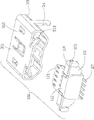
The schematic perspective view that Fig. 1 matches with pin connector for socket connector of the present invention.
Schematic perspective view when Fig. 2 does not dock with pin connector for socket connector of the present invention.
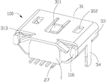
Fig. 3 is the three-dimensional combination figure of socket connector of the present invention.
Fig. 4 is the three-dimensional combination figure of another angle of socket connector of the present invention.
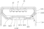
Fig. 5 is the front view of socket connector of the present invention.
Fig. 6 is the part three-dimensional exploded view of socket connector of the present invention.
Fig. 7 is the part three-dimensional exploded view of another angle of socket connector of the present invention.
Fig. 8 is the three-dimensional exploded view of socket connector of the present invention.
Fig. 9 is the three-dimensional exploded view of another angle of socket connector of the present invention.
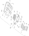
Figure 10 is the part stereogram of pin connector of the present invention.
Figure 11 is the three-dimensional exploded view of pin connector of the present invention.
[embodiment]
See also Figure 1 and Figure 2, the present invention includes and be called for short plug 900 behind the pin connector 900() and a socket connector 100(after be called for short socket 100), the butt connector that formation can be pegged graft mutually between described plug 900 and the socket 100.
See also Fig. 3 to shown in Figure 7, described socket 100 comprises first body 1, be immobilizated in some first conducting terminals 2 on first body 1 and coat first shielding casing 3 of first body 1, and described first shielding casing 3 is provided with in order to accommodate first receiving space 30 of banjo 900.
Described first body 1 comprises first base portion 11 and gives prominence to first hyoplastron 12 of first base portion 11 forward.Described first hyoplastron, 12 along continuous straight runs extend, and it comprises upper surface 121 and and upper surface 121 opposing lower surface 122.Described lower surface 122 is provided with some spaced terminal containing slots 1221 and gives prominence to the fin 1222 that adjacent two accepting grooves 1221 are separated downwards from lower surface 122.Described fin 1222 is in order to be in contact with one another preventing each first conducting terminal 2 is spaced apart.In the present embodiment, described first body 1 is made by insulating material, and described first base portion 11 and first hyoplastron, 12 one are extended and formed.Certainly, in other embodiments, described first hyoplastron 12 can be arranged with first base portion in 11 minutes, and the mode with assembling combines then.Described first base portion 11 is provided with the front surface 110 that links to each other with first hyoplastron 12, rear surface 111, end face 112, bottom surface 113 and two sides 114 relative with front surface 110.Described end face 112, bottom surface 113 and two sides 114 are respectively equipped with some raised lines 115 to interfere mutually with first shielding casing 3.Described first base portion 11 also be provided with from the rear surface 111 with 114 joints, two sides laterally the outstanding a pair of projection 116 that extends to match with shielding casing 3.Described first base portion 11 also be provided with from the bottom surface 113 middle parts to end face 112 directions be recessed to form a depressed part 1131 and from the rear surface 111 projections 1132 that extend downwards with 113 joints, bottom surface, described projection 1132 is positioned at the rear of described depressed part 1131.Described terminal containing slot 1221 extends back and runs through described projection 1132 downwards.
See also Fig. 7 and shown in Figure 8, described first conducting terminal 2 only comprises two types of earth terminal and difference signal terminal, and described first conducting terminal 2 only comprises two pairs of difference signal terminal and an earth terminal G between these two pairs of difference signal terminal, wherein, described two pairs of difference signal terminal comprise a pair of vision signal terminal 21 and a pair of mixed signal terminal (Hibrid Channel) 22.Described first the putting in order of conducting terminal 2 is followed successively by: a pair of vision signal terminal 21, earth terminal G, a pair of mixed signal terminal 22.Described each difference signal terminal is included a positive signal terminal and a negative signal terminal.Described earth terminal G is positioned between two pairs of difference signal terminal 21,22 can widen two pairs of distances between the difference signal terminal 21,22, and the signal that further weakens between two pairs of adjacent difference signal terminal 21,22 disturbs.Each vision signal terminal 21 one-way transmission vision signal; And two mixed signal terminals (Hibrid Channel) 22, in order to transmission of audio signal and other data-signal of transmitted in both directions, to reach transmission speed faster.In addition, totally 5 of first conducting terminals 2 of socket 100 among the present invention, number is less, and is simple in structure, and then can reduce volume and the materials cost of socket 100, to adapt to the development trend of miniaturization of electronic products.And described first conducting terminal 2 only comprises two types, and the function of first conducting terminal, 2 correspondences is simple relatively, uncomplicated, and then is convenient to the design of circuit board with matching or chip, is convenient to the utilization and extention of socket 100.In addition, only just comprise two pairs of difference signal terminal 21,22 in 5 first conducting terminals 2, can reach faster data transmission speed.
On structure, each first conducting terminal 2 be provided with the holding parts 25 that is fixed on first base portion 11, from holding parts 25 extend forward and be accommodated in tabular contact site 26 in the terminal containing slot 1221, in order to the weld part 27 of connecting circuit plate and connect the connecting portion 28 of holding parts 25 and weld part 27.Described contact site 26 and weld part 27 equal along continuous straight runs extend.See also shown in Figure 5, look up from the butt joint side of socket 100, be arranged as a ranking on described contact site 26 along continuous straight runs in the same side of first hyoplastron 12 (being on the lower surface 122 of first hyoplastron 12 in the present embodiment), so that the thickness of first hyoplastron 12 reduces, the general thickness of socket 100 also is minimized.Described contact site 26 is exposed to downwards in first receiving space 30, electrically connects with banjo 900 with convenient.Described weld part 27 is to be welded on the circuit board (not shown) in the mode that install on the surface.
In the present embodiment, described first conducting terminal 2 is to be stamped to form by metal material belt, and is installed on first body 1 in Overmolded mode.Certainly, in other embodiments, first conducting terminal 2 also can be fixed on first body 1 by the mode of assembling.
Described first shielding casing 3 by the punching press of a slice metal material, be bent to form.Described first shielding casing 3 comprise first roof 31 relative with the upper surface 121 of first hyoplastron 12, first diapire 32 relative with the lower surface 122 of first hyoplastron 12 and be connected in first roof 31 and first diapire 32 between two sidewalls 33.Described first receiving space 30 is between first roof 31 and first diapire 32.Described first roof 31 is provided with compressing shell fragment 311, be positioned at the bonnet lock hole 312 that compresses shell fragment 311 both sides and tear a pair of shell fragment 313 that compresses of formation from first roof, 31 rear sides of extending back.Described compress elastic arm 313 comprise the flat part that exceeds first body, 1 rear end of extending back from first roof, 31 middle parts, from the dovetail shaped alar part that plate part does not extend to both sides, described alar part is tilted to down so that support before the side direction of alar part on the rear surface 111 of first body 1 along body 1 Width.The described elastic arm 313 that compresses compresses first body 1 and is fixed in first shielding casing 3 to first receiving space, 30 directions.Described each sidewall 33 includes the first side wall 331 that is connected with first roof 31 and second sidewall 332 that tilts to be connected the first side wall 331 and first diapire 32.Described second sidewall 332 tilts to be connected respectively with the first side wall 331 and first diapire 32 and forms a angle, and described a angle is the miter angle that up-down error is no more than 5 degree.Described second sidewall 332 along first body, 1 Width between the first side wall 331 and first diapire 32, thereby described first roof 31 along the width of the Width of first body 1 greater than the width of first diapire 32 along the Width of first body 1.All be connected by an arc surface transition between described first roof 31 and the first side wall 331, between described the first side wall 331 and second sidewall 332 and between described second sidewall 332 and described first diapire 32.Described first shielding casing 3 also is provided with from the vertical installation foot 34 that extends of the first side wall 331 lower ends downward in order to electric connector for socket 100 is positioned on the circuit board.
Described first diapire 32 comprise the first wall 321 that extends internally in opposite directions respectively from two second sidewall, 332 lower ends, from two first walls 321 be inclined upwardly in opposite directions second wall 322 that extends, and connect the 3rd wall 323 of two second walls 322.Described first wall 321 and the 3rd wall 323 all parallel with first roof 31, and described the 3rd wall 323 is positioned at the top of first wall 321 and second wall 322.Described two first walls 321 are positioned at same plane, and equate along the width that first body, 1 Width extends.The width that the width that described the 3rd wall 323 extends along the Width of first body 1 extends greater than each first wall 321, and described the 3rd wall 323 is between first roof 31 and first wall 321.Described first wall 321, second wall 322 and the 3rd wall 323 are combined to form in order to prevent that other unmatched plug from inserting the anti-mis-insertion structure in first receiving space 30.The distance of the upper surface 121 of described first roof 31 and first hyoplastron 12 is less than the distance between the lower surface 122 of described first diapire 32 and first hyoplastron 12.
In sum, form corresponding first interface (frame of broken lines among ginseng Fig. 5) of Micro USB 2.0 B Type pin connectors that holds standard between the part of the first side wall 331 of the 3rd wall 323 of described first diapire 32, first roof 31, two sidewalls 33, second sidewall 332 and first hyoplastron 12.Form second interface corresponding with Micro Diiva pin connector between described first roof 31, two sidewalls 33, whole first diapire 32 and first hyoplastrons 12.
Please join Fig. 1, Fig. 2, Figure 10 and shown in Figure 11, plug 900 comprises one second body 4, is retained on some second conducting terminals 5 on second body 4 and snap close terminal 6, the keeper 71 of location second conducting terminal 5, hides the second metal shielding casing 8 of second body 4 and be connected in the cable 9 of plug 900 rear ends among the present invention.
Described second body 4 comprises second base portion 41 and second hyoplastron 42 that extends forward from second base portion 41.Described second hyoplastron 42 is provided with upper surface 421 and lower surface 422.Described upper surface 421 middle parts are concaved with one and run through second hyoplastron, 42 front ends to accommodate second receiving space 43 of first hyoplastron 12 on the socket 100, and described second receiving space 43 is formed with a bottom surface 431.The lower surface 422 curves design of described second hyoplastron 42, roughly similar with first diapire, 32 profiles of socket 100, it comprises first 4221 that is positioned at two ends, lower surface 422 left and right sides, from second 4222 of two first 4221 extensions that are inclined upwardly in opposite directions respectively, reach the 3rd 4223 that connects two second 4222.Described first 4221 all parallels with upper surface 421 with the 3rd 4223, and the 3rd 4223 is positioned at first 4221 top.
The bottom surface 431 of described second receiving space 43 is concaved with some terminal containing slots 432 that are through to second body, 4 rear ends.Described second conducting terminal 5 is contained in the terminal containing slot 432, and is provided with and extends in second receiving space 43 and the elastic contact part 54 of curved design.The two ends, the left and right sides of described upper surface 422 are concaved with one respectively and are through to second hyoplastron, 42 lower surfaces 422 and are communicated to the holding slot 4231 of second base portion, 41 rear ends in the outside of second receiving space 432.Described snap close terminal 6 is retained in this holding slot 4231 and is provided with the elastic lock portion 63 of extending upper surface 421 tops.
First conducting terminal, 2 corresponding settings on described second conducting terminal 5 and the socket 100 had both also comprised two pairs of difference signal terminal and an earth terminal G between these two pairs of difference signal terminal.Corresponding a pair of vision signal terminal 51 and a pair of mixed signal terminal (Hibrid Channel) 52 of being set on these two pairs of difference signal terminal and the socket 100.Described earth terminal G is positioned between two pairs of difference signal terminal 21,22, can widen two pairs of distances between the difference signal terminal 51,52, and further weakens the interference between two pairs of adjacent difference signal terminal 51,52.In addition, the front end of affiliated earth terminal G is than two pairs of difference signal terminal 51, the 42 front end settings of 52 more close second hyoplastrons, then when when combination hub 100 is pegged graft, described earth terminal G can be earlier and the earth terminal G on the socket 100 electrically conduct, eliminate extraneous electrostatic interference so that two pairs of difference signal terminal 51,52 signal transmission environment preferably to be provided.Same, each vision signal terminal 51 one-way transmission vision signal; And mixed signal terminal (Hibrid Channel) 52 is in order to transmission of audio signal and other data-signal of transmitted in both directions, to reach transmission speed faster.
On structure, each second conducting terminal 5 is provided with the holding parts 53 that is fixed on second base portion 41, extends forward and be accommodated in described arc-shaped contact part 54 in the terminal containing slot 432, and extend back with the connecting portion 55 of connection cable 9 from holding parts 53 from holding parts 53.See also shown in Figure 7ly, look up from the butt joint side of plug 900, be arranged as a row on described contact site 54 along continuous straight runs, and described contact site 54 is positioned at the same side (being on the upper surface 431 of second hyoplastron 42 in the present embodiment) of second hyoplastron 42.Described contact site 54 elasticity upwards are exposed in second receiving space 43 conveniently with to combination hub 100 to electrically connect.
Totally 5 of second conducting terminals 5 of plug 900 of the present invention, number is less, and is simple in structure, and then can reduce volume and the materials cost of plug 900, to adapt to the development trend of miniaturization of electronic products.In addition, described second conducting terminal 5 only comprises two types, and the function of second conducting terminal, 5 correspondences is simple relatively, uncomplicated, and then is convenient to the design of circuit board with matching or chip, is convenient to the utilization and extention of pin connector 900.In addition, describedly only just comprise two pairs of differential signals, second conducting terminal 51,52 in 5 second conducting terminals 5, can reach faster data transmission speed.
Described locating piece 71 is retained on the rear end of second body 4, it is provided with somely spacedly up and down wears mouthfuls 710 adjacent second conducting terminal, 5 rear ends being separated to prevent from being in contact with one another and be short-circuited, and the connecting portion 55 that supports second conducting terminal 5 simultaneously is stably to be connected with cable 9.
Described second shielding casing 8 comprises the docking section 81 that is coated on around second hyoplastron 42.Described docking section 81 comprises second roof 811, second diapire 812 and two end walls 813 that are posted by second hyoplastron, 42 upper surfaces 421, lower surface 422 and both sides respectively.Described second receiving space 43 is formed between second roof 811 and the bottom surface 431.The profile of the structure of described second diapire 812 and second hyoplastron, 42 lower surfaces 422 and first diapire 32 is basic identical in order to coat the lower surface 422 of second hyoplastron 42, and can insert in the receiving space 30 of socket 100.The end wall 813 of described second shielding casing 8 includes first end wall that connects second roof 811 and second end wall that tilts to connect first end wall and second diapire 812, described second diapire 812 be provided with from the second end wall downside bend inwards two first walls extending, two second walls that extend and the 3rd wall that connects two second walls slope inwardly respectively from two first wall the inners, first 4221 of described first wall and second body 4 reclines, described second wall and second 4222 recline, and described the 3rd wall and the 3rd 4223 recline.Tilt to be connected to form the angle that is roughly 45 degree between described second end wall and described first end wall and the first wall respectively.Described second roof 811 is provided with the opening 8111 with the 63 corresponding settings of described elastic lock portion, and two between two openings 8111 interfere bars 8112 with socket 100 on 31 interferences of first roof.Described latch part 63 is passed opening 8111 and is extended to second roof, 811 outsides.Describedly compress shell fragment 311 and second roof 811 is interfered mutually, latch part 63 and lockhole 312 forms latching devices, add between sidewall 33 and the end wall 813 and offset respectively, thereby make plug 900 and to forming multiple fastener between the combination hub 100 or supporting, strengthen retain strength between the two, guarantee the firm transmission of signal between the two.
In sum, it below only is preferred embodiment of the present invention, should not limit the scope of the invention with this, namely every simple equivalent of doing according to claims of the present invention and description changes and modifies, and all should still belong in the scope that patent of the present invention contains.
Claims (10)
1. socket connector, be applicable to the two kinds of different pin connectors of pegging graft, described socket connector comprises: body, the shielding casing that is fixed in the some conducting terminals on the body and hides body, described shielding casing is provided with the receiving space of accommodating pin connector, be positioned at the roof of receiving space upper and lower sides, diapire and be connected in roof and diapire between two sidewalls, described body is provided with base portion and extends forwardly to the hyoplastron of receiving space from base portion, described conducting terminal is provided with the contact site that extends on the hyoplastron, it is characterized in that: the sidewall of described shielding casing includes the first side wall that connects roof and second sidewall that connects the first side wall and diapire, described diapire is provided with two first walls that bend inwards and extend from the second sidewall downside, two second walls that tilt to extend in the receiving space respectively from two first wall the inners and the 3rd wall that connects two second walls, described second sidewall and described the first side wall and first wall form respectively and are roughly 45 angles of spending.
2. socket connector as claimed in claim 1 is characterized in that: be parallel to each other between described first wall and the 3rd wall and the roof, described second wall and the 3rd wall all be positioned at hyoplastron under, described the 3rd wall is between roof and first wall.
3. socket connector as claimed in claim 2, it is characterized in that: described the 3rd wall is positioned at first wall top, and with roof, two the first side walls and two second sidewalls and hyoplastron between form the Micro USB 2.0 B Type pin connectors of standard corresponding first insert contact opening.
4. socket connector as claimed in claim 3 is characterized in that: form pin connector corresponding second interface different with another kind between described roof, two the first side walls, two second sidewalls, whole diapire and hyoplastrons.
5. socket connector as claimed in claim 1, it is characterized in that: described hyoplastron is provided with upper surface towards roof, towards the lower surface of diapire and from the outstanding some fins of lower surface, described conducting terminal is between adjacent two fins, and described contact site is the lower surface that tabular is arranged in hyoplastron.
6. socket connector as claimed in claim 5 is characterized in that: the lower surface of described hyoplastron to the distance of diapire greater than the upper surface of the described hyoplastron distance to roof.
7. socket connector as claimed in claim 1 is characterized in that: described roof is provided with and extends into the compress shell fragment of receiving space to interlock and to hold with pin connector, and be positioned at compress the shell fragment both sides with the bonnet lock hole of butt connector snap close.
8. socket connector as claimed in claim 1, it is characterized in that: described shielding casing also is provided with the elastic arm that compresses that tears formation from the roof rear side, and the described elastic arm that compresses compresses body with the location body to the receiving space direction.
9. socket connector as claimed in claim 8, it is characterized in that: described compress elastic arm comprise the flat part that exceeds the body rear end of extending back from roof middle part, from the dovetail shaped alar part that plate part does not extend to both sides, described alar part is tilted to down so that support the body rear end before the side direction of alar part along the body Width.
10. pin connector, it comprises: body, the shielding casing that is fixed in the some conducting terminals on the insulating body and hides body, described shielding casing is provided with corresponding roof, diapire and be connected in roof and diapire between two end walls, the hyoplastron that described body is provided with base portion and extends forward from base portion, described conducting terminal is provided with the elastic contact part that extends on the hyoplastron, it is characterized in that: the end wall of described shielding casing includes first end wall that connects roof and second end wall that tilts to connect first end wall and diapire, described diapire is provided with two first walls that bend inwards and extend from the second end wall downside, slope inwardly respectively from two first wall the inners two second walls that extend and the 3rd wall that connects two second walls tilt to be connected to form to be roughly 45 angles of spending respectively between described second end wall and described first end wall and the first wall.
Priority Applications (1)
| Application Number | Priority Date | Filing Date | Title |
|---|---|---|---|
| CN 201210064976 CN103208696A (en) | 2012-01-13 | 2012-01-13 | Socket connector and plug connector |
Applications Claiming Priority (1)
| Application Number | Priority Date | Filing Date | Title |
|---|---|---|---|
| CN 201210064976 CN103208696A (en) | 2012-01-13 | 2012-01-13 | Socket connector and plug connector |
Publications (1)
| Publication Number | Publication Date |
|---|---|
| CN103208696A true CN103208696A (en) | 2013-07-17 |
Family
ID=48755833
Family Applications (1)
| Application Number | Title | Priority Date | Filing Date |
|---|---|---|---|
| CN 201210064976 Pending CN103208696A (en) | 2012-01-13 | 2012-01-13 | Socket connector and plug connector |
Country Status (1)
| Country | Link |
|---|---|
| CN (1) | CN103208696A (en) |
Cited By (2)
| Publication number | Priority date | Publication date | Assignee | Title |
|---|---|---|---|---|
| CN108649365A (en) * | 2018-05-10 | 2018-10-12 | 维沃移动通信有限公司 | A kind of plug, socket, data line and mobile terminal |
| CN111244679A (en) * | 2020-02-19 | 2020-06-05 | 昆山德普福电子科技有限公司 | Connector integrated plug and connector integrated assembly |
-
2012
- 2012-01-13 CN CN 201210064976 patent/CN103208696A/en active Pending
Cited By (2)
| Publication number | Priority date | Publication date | Assignee | Title |
|---|---|---|---|---|
| CN108649365A (en) * | 2018-05-10 | 2018-10-12 | 维沃移动通信有限公司 | A kind of plug, socket, data line and mobile terminal |
| CN111244679A (en) * | 2020-02-19 | 2020-06-05 | 昆山德普福电子科技有限公司 | Connector integrated plug and connector integrated assembly |
Similar Documents
| Publication | Publication Date | Title |
|---|---|---|
| US9614310B2 (en) | Standing-type electrical receptacle connector | |
| CN201397899Y (en) | Electric connector | |
| CN102290654B (en) | Electric connector | |
| CN102931521B (en) | Cable connector component | |
| CN102544802B (en) | Cable connector component | |
| US7695318B1 (en) | Plug connector | |
| JP3163905U (en) | High frequency micro connector | |
| CN2840402Y (en) | Electric connector | |
| CN102931523B (en) | Cable connector component | |
| CN104064915B (en) | Electric connector | |
| US8202120B2 (en) | High frequency socket connector | |
| CN102931522B (en) | Cable connector component | |
| CN102195223B (en) | Electrical connector and complex thereof | |
| US9325125B2 (en) | Electrical connector having a contact arrangement to improve the quality of the signal transmission | |
| CN102957013A (en) | Cable plug connector, board terminal socket connector and connector component | |
| CN203026652U (en) | Cable connector assembly | |
| US8075345B2 (en) | Electrical connector | |
| CN104347972A (en) | Electrical connector | |
| CN205282752U (en) | Electric connector | |
| CN102570091A (en) | Cable connector component | |
| CN202159800U (en) | Cable plug connector, board end socket connector and connector assembly | |
| CN205882311U (en) | USBC type electric connector | |
| CN201230095Y (en) | Electric connector | |
| CN201204298Y (en) | Electric connector | |
| CN203351889U (en) | Plug connector and socket connector |
Legal Events
| Date | Code | Title | Description |
|---|---|---|---|
| C06 | Publication | ||
| PB01 | Publication | ||
| C05 | Deemed withdrawal (patent law before 1993) | ||
| WD01 | Invention patent application deemed withdrawn after publication |
Application publication date: 20130717 |