CN103163329A - Acceleration signal processing device - Google Patents
Acceleration signal processing device Download PDFInfo
- Publication number
- CN103163329A CN103163329A CN2012105210454A CN201210521045A CN103163329A CN 103163329 A CN103163329 A CN 103163329A CN 2012105210454 A CN2012105210454 A CN 2012105210454A CN 201210521045 A CN201210521045 A CN 201210521045A CN 103163329 A CN103163329 A CN 103163329A
- Authority
- CN
- China
- Prior art keywords
- acceleration
- microcomputer
- switch
- substrate
- mass body
- Prior art date
- Legal status (The legal status is an assumption and is not a legal conclusion. Google has not performed a legal analysis and makes no representation as to the accuracy of the status listed.)
- Pending
Links
Images

Classifications
-
- G—PHYSICS
- G01—MEASURING; TESTING
- G01P—MEASURING LINEAR OR ANGULAR SPEED, ACCELERATION, DECELERATION, OR SHOCK; INDICATING PRESENCE, ABSENCE, OR DIRECTION, OF MOVEMENT
- G01P15/00—Measuring acceleration; Measuring deceleration; Measuring shock, i.e. sudden change of acceleration
-
- G—PHYSICS
- G01—MEASURING; TESTING
- G01C—MEASURING DISTANCES, LEVELS OR BEARINGS; SURVEYING; NAVIGATION; GYROSCOPIC INSTRUMENTS; PHOTOGRAMMETRY OR VIDEOGRAMMETRY
- G01C22/00—Measuring distance traversed on the ground by vehicles, persons, animals or other moving solid bodies, e.g. using odometers, using pedometers
- G01C22/006—Pedometers
-
- G—PHYSICS
- G01—MEASURING; TESTING
- G01P—MEASURING LINEAR OR ANGULAR SPEED, ACCELERATION, DECELERATION, OR SHOCK; INDICATING PRESENCE, ABSENCE, OR DIRECTION, OF MOVEMENT
- G01P13/00—Indicating or recording presence, absence, or direction, of movement
-
- G—PHYSICS
- G01—MEASURING; TESTING
- G01P—MEASURING LINEAR OR ANGULAR SPEED, ACCELERATION, DECELERATION, OR SHOCK; INDICATING PRESENCE, ABSENCE, OR DIRECTION, OF MOVEMENT
- G01P15/00—Measuring acceleration; Measuring deceleration; Measuring shock, i.e. sudden change of acceleration
- G01P15/02—Measuring acceleration; Measuring deceleration; Measuring shock, i.e. sudden change of acceleration by making use of inertia forces using solid seismic masses
- G01P15/08—Measuring acceleration; Measuring deceleration; Measuring shock, i.e. sudden change of acceleration by making use of inertia forces using solid seismic masses with conversion into electric or magnetic values
- G01P15/135—Measuring acceleration; Measuring deceleration; Measuring shock, i.e. sudden change of acceleration by making use of inertia forces using solid seismic masses with conversion into electric or magnetic values by making use of contacts which are actuated by a movable inertial mass
-
- H—ELECTRICITY
- H01—ELECTRIC ELEMENTS
- H01H—ELECTRIC SWITCHES; RELAYS; SELECTORS; EMERGENCY PROTECTIVE DEVICES
- H01H35/00—Switches operated by change of a physical condition
- H01H35/14—Switches operated by change of acceleration, e.g. by shock or vibration, inertia switch
- H01H35/144—Switches operated by change of acceleration, e.g. by shock or vibration, inertia switch operated by vibration
Abstract
In an acceleration sensor, it has been difficult to realize a circuit which has no current consumption at all during OFF of a system and is capable of activating a sensor main body when applied with vibration. Provided is an acceleration switch having one terminal connected to one of a positive power supply or a negative power supply, and another terminal connected to an interrupt input terminal of a microcomputer.
Description
Technical field
The present invention relates to the acceleration signal treating apparatus.
Background technology
All the time, passometer is utilized, and described passometer is installed on user's waist etc. and uses, and uses under the state that perhaps carries being contained in carry bag, and utilizes sensor to detect user's walking, thereby measure step number.This passometer constitutes at display part and shows step number.Here, the demonstration data (step Numerical) (for example, with reference to patent documentation 1) of existing passometer update displayed section when the walking signal that at every turn detects from acceleration transducer.
In addition, all the time, there is the passometer of the mode be installed on arm or waist and use in passometer.For example, in the arm passometer that uses being installed on arm, in order to improve the pedometer accuracy of measurement, can consider to detect that arm swings and method that every two steps measure, or detect that health moves up and down and (with reference to patent documentations 2) such as methods that per step measures.
In addition, usually, owing to not too seeing the demonstration of passometer when the walking, so proposed following scheme: detect the state of the lid of closing the passometer housing, perhaps, detect the state that passometer is installed on clothes, stop display action and carry out power saving.Yet, due to need to be for detection of the switch of the switching of the lid of passometer housing, detect the situation switch that has been installed on clothes etc., so because the increase of specialized hardware is risen cost, or be difficult to carry out miniaturization.In addition, need to be used for the control etc. of the state-detection of switch, structure complicates.
Above countermeasure is all considered in order to extend with the battery life of battery-driven passometer.This is because the current sinking of the acceleration signal treating apparatus that uses in passometer is larger.Reason is microcomputer is moved all the time, can detect all the time the vibration that puts on acceleration switch.And the detection that microcomputer needs driving sensor all the time and will carry out the output signal of sensor is prepared.Under such situation, can not extend the battery life of passometer.
[prior art document]
[patent documentation]
[patent documentation 1] Japanese kokai publication sho 57-48176 communique;
[patent documentation 2] TOHKEMY 2007-307218 communique.
Summary of the invention
Yet, in the prior art, in the situation that made up the acceleration signal treating apparatus of the passometer of acceleration transducer and microcomputer, need to drive all the time the sensor that detects vibration or acceleration and supply with the power supply that is used for making the microcomputer action.Particularly, in the equipment situation of the battery that is merely able to carry low capacity of packing into, need following structure: be made as holding state by the system that will comprise the acceleration signal treating apparatus when not detecting vibration, make system acting when detecting vibration, thereby do not use lavishly battery electric power.Even in the system that consists of like this, the current sinking during due to standby, battery life are about 1 ~ 2 year.
The such situation of the present invention's consideration is made, and its purpose is, the technology that the battery life of passometer can be extended to about 5 years is provided.Particularly, use the acceleration switch of Fig. 2, in passometer no vibration or when only having applied than the little vibration of set value fully, microcomputer and sensor in the acceleration signal treating apparatus of passometer are stopped fully.
On the other hand, be provided at the acceleration signal treating apparatus that starts described microcomputer and sensor when acceleration switch is applied vibration more than set value.In foregoing, during vibration more than applying set value, particularly refer to the vibration when passometer is installed on health after startup.
Below, in order to solve above-mentioned problem, providing the acceleration signal treating apparatus in mode of the present invention, described acceleration signal treating apparatus has: power supply unit has supply voltage; Acceleration switch, supply voltage is supplied to one electrode from a utmost point of power supply unit; Microcomputer is connected with another electrode of acceleration switch; And sensor main body, can exchange signal with microcomputer two-wayly, and accept to start or stop from the signal of microcomputer, export acceleration information to microcomputer when starting.
Further, mode of the present invention is characterised in that also have load elements, and the one end is connected between acceleration switch and microcomputer, and the other end of load elements is connected to another utmost point of power supply unit.
Further, mode of the present invention is characterised in that, load elements comprise resistance, capacitor or transistorized at least one.
Further, mode of the present invention is characterised in that, acceleration switch has: the mass body that has living space at the inboard band; Support the beam of mass body; And the opposite electrode that is positioned at the space.
Further, mode of the present invention is characterised in that, acceleration switch is to contact the switch that switches to conducting (ON) with opposite electrode by mass body, the gap of mass body and opposite electrode is in the situation that the gap that the vibrational energy mass body more than the additional set value of acceleration switch is contacted with opposite electrode.
Further, mode of the present invention is characterised in that, set value is the accekeration of people when having begun to move.
By adopting such structure, in the acceleration signal treating apparatus of acceleration switch, make at least one startup of microcomputer or acceleration transducer by the conducting state of utilizing acceleration switch, making before this, microcomputer or the acceleration transducer of hold function start.The acceleration signal treating apparatus of the microcomputer when thus, realize suppressing hold function or the current sinking of acceleration transducer and described acceleration switch is the device of current sinking not also.
Particularly, in the acceleration signal treating apparatus of acceleration switch, has such unit, its by configuration between positive supply and negative supply by acceleration switch and resistance or capacitor or element that both consist of or the active component that consisted of by transistor etc., thereby acceleration switch is worked effectively.
[effect of invention]
According to acceleration signal treating apparatus of the present invention, can be structured in the vibration that puts on acceleration switch and hour reduce significantly the system of the drive current of acceleration signal treating apparatus than set value.
Description of drawings
Fig. 1 is the schematic diagram that the embodiment of acceleration signal treating apparatus of the present invention is shown.
Fig. 2 is the schematic cross section of known acceleration switch in the past.
Fig. 3 is the schematic longitudinal sectional view of known acceleration switch in the past.
Fig. 4 is the key diagram of the action of known acceleration switch in the past.
Fig. 5 illustrates the schematic cross section of the embodiment of known acceleration switch in the past.
Embodiment
[embodiment 1]
Below, with reference to accompanying drawing, a mode that is used for implementing the best of the present invention is described.
At first, structure and the action of the first acceleration switch in Japanese appearance design document are described.
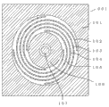
Fig. 5 is the figure that observes from upper surface side, and the space in mass body inside that its explanation is seen for No. 1310053 in Japanese appearance design registration has the structure of the non-directive acceleration switch 001 of opposite electrode.The 101st, the periphery of acceleration switch 001 (housing), from 102 to 105 is the beams that support weight 106.The 107th, opposite electrode.Yet, many and complicated because beam has 4, so replace Fig. 5, be described in detail for the situation of 1 beam with Fig. 2.In addition, following record is not that the shape of 4 beams shown in Figure 5 is excluded in outside scope of the present invention, but puts down in writing in order to describe embodiments of the invention more simply.
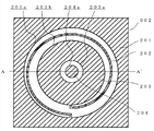
Fig. 2 is the figure that the upper surface side of the second acceleration switch 002 in the situation of 1 beam is as described above observed.But, in fact have the layer (the 1st substrate 205 shown in Figure 3) become lid on it, with and under have supporting layer (the 3rd substrate 206 shown in Figure 3).Fig. 3 is the sectional view that cuts out at A-A ' face shown in Figure 2, also is included in abridged layer in Fig. 2.Fig. 2 is equivalent to the figure that cuts out at the B-B ' of Fig. 3 face in addition.
As Fig. 2 ~ shown in Figure 3, acceleration switch 002 by from the 1st substrate (cap rock) 205 of the insulating material such as the stacked use glass of upper beginning, use the 2nd substrate 201(of single crystal silicon etc. also to comprise 202,203,204) and use the 3rd substrate (supporting layer) 206 of the insulating material such as glass to consist of.The single crystal silicon of the 2nd substrate to conduct and for example uses low-resistance silicon in order to obtain.In addition, through electrode 207 and 208 forms by imbedding the metals such as gold, becomes to make acceleration switch and the outside contact that links.In addition, the 1st substrate utilizes the methods such as anodic bonding to engage with the 2nd substrate with the 3rd substrate.
Below, describe with reference to the concrete shape of the embodiment 1 of Fig. 2 and 3 pairs of acceleration switchs 002 of the present invention.
At first, inboard from the lateral of Fig. 2, the 2nd substrate of acceleration switch 002 consists of according to the order of substrate periphery section 201, beam 202, mass body 203 and opposite electrode 204.
Except the junction surface of described later and beam 202, substrate periphery section 201 also has digs its approximate centre in Fig. 2 that to wear be columned interior all shapes (substrate the inside 201a).And substrate periphery section 201 utilizes the 1st substrate 205 and upside and the downside of the 3rd substrate 206 from Fig. 3 in Fig. 3 to clamp.Though the mode of chucking substrate periphery 201 is not particularly limited, in the present embodiment, the mode that the oblique line section gamut that spreads all over shown in Figure 2 substrate periphery section 201 is clamped by the 1st substrate 205 and the 3rd substrate 206 is shown.
In the present embodiment, through electrode 207 and 208 has shape or the cone shape that the upper surface of the 1st substrate 205 from Fig. 3 attenuates towards the depth direction front end.And through electrode 207 and 208 does not contact mutually, form run through the 1st substrate 205 until respectively with Fig. 3 in substrate periphery section 201 and opposite electrode 204 degree of depth of joining.In addition, in order to connect reliably through electrode 207 and 208 and substrate periphery section 201 and opposite electrode 204, form respectively recess 201b and 204b in substrate periphery section 201 and opposite electrode 204, make the front end of through electrode 207 and 208 enter recess 201b and 204b.In addition, the effect of through electrode is to obtain respectively conducting of substrate periphery section 201 and counter electrode 204, so as long as join respectively with substrate periphery section 201 and opposite electrode 204, can be shape arbitrarily.
Here, substrate periphery section 201 is clamped by the 1st substrate 205 in Fig. 3 and the 3rd substrate 206 with opposite electrode 204, but as mentioned above, the 1st substrate 205 and the 3rd substrate 206 are formed by insulating material, thereby substrate periphery section 201 does not conduct with opposite electrode 204.
In addition, in the present embodiment, the 1st substrate 205 and the surface that substrate periphery section 201 and opposite electrode 204 join form to substrate periphery section's 201 sides and opposite electrode 204 side-prominent.Its purpose is easily between above-mentioned beam 202 and mass body 203 and the 1st substrate 205, the space to be set.Therefore, in the surface that the 3rd substrate 206 and substrate periphery section 201 and opposite electrode 204 join, the 3rd substrate 206 also can be to form to substrate periphery section's 201 sides and the side-prominent mode of opposite electrode 204.
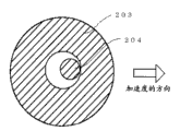
Here, when applying acceleration along the direction of arrow as shown in Figure 4, acceleration switch 002 integral body is not moved by the mass body 203 that beam 202 supports to arrow direction, thereby the opposite electrode 204 that is positioned at the space of mass body inside contacts with mass body 203.In addition, for easy understanding, omitted beam 202 and the substrate periphery section 201 of mass body 203 peripheries in Fig. 4.Thus, conduct from opposite electrode 204 and begin to be connected with external connector by mass body 203, beam 202, substrate periphery section 201, through electrode 207.In addition, opposite electrode 204 is connected with external connector by another through electrode 208.
In addition, as embodiment more specifically, the gap of regulation opposite electrode 204 and mass body 203.In the present embodiment, this gap is decided to be, and makes that opposite electrode 204 contacts with mass body 203 when mass body 203 being applied vibration more than set value or gravity, and acceleration switch 002 starts.For example be decided to be, make in the situation that the load more than 0.8G ~ 1.2G is additional to acceleration switch 002 mass body 203 contacts with opposite electrode 204.This set value is the accekeration of people when having begun to move.Particularly, be suitable for most starting the conception of the situation of the load more than additional 1G for making this acceleration switch in the situation that adopt the such module of acceleration switch in the electronic equipment of passometer etc.
Being defined as the reason that starts by for example above load of 0.8G ~ 1.2G can enumerate, and is commonly referred to as little vibration of vibration noise, and it is most the vibration this point less than 0.8G.And, can enumerate this point, namely the arm of passometer, waist are being installed, in the situation that the vibrational energy that the metering step number is additional to passometer illustrates the numerical value more than general 0.8G.Particularly, the gravity that is additional to waist during walking due to beginning has the weight over the load of 1.5G, so by stipulating this gap, according to the kind of passometer, can set the timing of the expectation that makes the acceleration switch conducting.
Thus, this acceleration switch makes acceleration switch conducting (obtaining the state of through electrode 207 and the conducting of 208) in the intensity of vibration when certain certain value is above, the disconnection during less than certain value of the intensity of vibration (not obtaining the state of through electrode 207 and 208 s' conducting).Interruption (Ge り Write body with this contact conducting, off-state input microcomputer and sensor element) input terminal starts microcomputer and sensor element.Use Fig. 1 at length to describe.
Fig. 1 is the circuit diagram that connects acceleration switch and microcomputer.Acceleration switch 002 is connected to one among 2 connecting lines (through electrode 208) utmost point of positive supply VDD(power supply unit, and VDD is supply voltage), another (through electrode 207) is connected to the interrupting input terminal 302 of microcomputer 301.In addition, the line ground connection (being connected with another utmost point, the negative supply VSS of power supply unit) that load 303 will not be connected with acceleration switch 002 and microcomputer 301, the interrupting input terminal 302 of microcomputer 301 is via load 303 ground connection.In other words, connect the line of acceleration switch 002 and load 303, the way has the tie point that is connected with microcomputer 301 therein.In addition, sensor main body 304 is connected to microcomputer 301.This sensor main body 304 is accepted to start or stop from the signal of microcomputer 301, exports acceleration informations to microcomputer 301 when starting.In other words, sensor main body 304 can with microcomputer 301 two-way ground receiving and transmitting signals.Here, the effect of load 303 is, determines the potential level of the interrupting input terminal 302 of microcomputer 301 when acceleration switch 002 disconnects.Therefore, consisted of by resistance or capacitor.
In addition, working load 303 can not completed this circuit yet.At this moment, with above-mentioned same, degree of will speed up switch is connected to the interrupting input terminal 302 of microcomputer 301, but different from above-mentioned structure, and load 303 is not set in the wiring of this circuit, and only connects a utmost point of this circuit and power supply unit.
In addition, also combined resistance or capacitor in series or in parallel of load 303.And the active components such as use transistor also can be realized same function.For the purpose of simplifying the description, below, load 303 is described as resistance 303.In addition, in Fig. 1, the switching input information of degree of will speed up switch to microcomputer 301, also can be reached the present invention but be made as the structure that is directly inputted into sensor main body 304 and sensor main body 304 is started in order to start microcomputer 301.
Then explanation action.Do not producing vibration or the state of acceleration or only applying under the state of the vibration less than set value, the repertoire of microcomputer 301 be halted state or only part of functions be opening, current sinking hardly.Owing to being the state that does not produce the state of vibration or acceleration or only apply the vibration less than set value, so the contact of acceleration switch 002 is open, be not connected with positive supply VDD, drop-down by resistance 303 to the input of interrupting input terminal 302, thereby be that Low(is low) (negative supply VSS).
Then, under the state that produces certain vibration more than certain value or acceleration, the junction closure of acceleration switch 002, positive supply VDD inputs to interrupting input terminal 302.At this moment, electric current flows via resistance 303, but the resistance value of resistance 303 is increased and suppresses this current sinking.The High(that is input to interrupting input terminal 302 is high) signal starts microcomputer 301.That is, the interrupting input terminal 302 of microcomputer 301 is the microcomputer of the type of interrupting at the High level.
In addition, be conceived to suppress this point of current sinking, also can adopt the structure of the configuration of transposing acceleration switch shown in Figure 1 002 and load 303.For the circuit structure of realizing expecting, these modes also optionally consist of.
The signal that the microcomputer 301 that starts will make sensor main body 304 start is sent to sensor main body 304, utilizes sensor main body 304 real-time vibration or the acceleration of metering.That is, acceleration switch 002 can be used in start sensor main body 304.
From this purpose, a end that also can degree of will speed up switch 002 is directly connected to sensor main body 304, not the start sensor main body 304 via microcomputer 301.Utilize this mode, can further improve sensor main body 304 for the response of vibration or acceleration.Generally speaking, sensor main body 304 is with low consumption current mode, but in the present invention, sensor main body 304 stopped, and makes the complete vanishing of its current sinking.Thus, can realize the further low current loss of system, the battery life of passometer was extended to about 5 years.
Under the state that vibration or the generation of acceleration stop, not from the signal of sensor main body 304, thereby microcomputer 301 can detect this situation.Under this state, owing to not needing to make in advance sensor main body 304 actions, so for low current loss, the action of sensor main body 304 is stopped.Thereafter, microcomputer 301 enters state that repertoire stops or the state opened of part of functions only, and current sinking is reduced.
In the present embodiment, describe at the example that the High level interrupts interrupting input terminal 302, but according to microcomputer, also have and interrupt at the Low level.In this case, opposite with embodiment by whole connections and state are made as, can obtain same effect.In the explanation of for example Fig. 1, positive supply (VDD) is changed on negative supply (VSS), drop-down being changed to draw, on draw and be changed to drop-down, High level and be changed to the Low level and get final product.
In addition, the circuit that uses in second acceleration switch shown in Figure 1 of explanation in the present embodiment has the versatility that can use in the first acceleration switch shown in Figure 5.Particularly, the difference of the first acceleration switch and the second acceleration switch is that beam is 1 or 4 this point, thereby circuit shown in Figure 1 certainly can not change the structure of through electrode 207 and 208 and use.
And though do not describe in detail in the mode of the first acceleration switch, first substrate 205 and the 3rd substrate 206 also can use above-mentioned structure same as before in mode shown in Figure 3 and embodiment.
In addition, in the present embodiment, concern is used the acceleration transducer of acceleration switch and is put down in writing especially, but uses mode of the present invention, be not limited to be called the element of acceleration transducer, can overall application in the element of well-known, sense vibrations or acceleration.
Description of reference numerals
001 first acceleration switch; The substrate periphery section of 101 first acceleration switchs; The beam of 102 first acceleration switchs; The beam of 103 first acceleration switchs; The beam of 104 first acceleration switchs; The beam of 105 first acceleration switchs; The mass body of 106 first acceleration switchs; The opposite electrode of 107 first acceleration switchs; 002 second acceleration switch; The substrate periphery section of 201 second acceleration switchs; The beam of 202 second acceleration switchs; The mass body of 203 second acceleration switchs; The opposite electrode of 204 second acceleration switchs; The 1st substrate of 205 acceleration switchs; The 3rd substrate of 206 acceleration switchs; The through electrode of 207 acceleration switchs; The through electrode of 208 acceleration switchs; 301 microcomputers; 302 interrupt terminal; 303 loads (resistance); 304 sensor main bodies.
Claims (6)
1. acceleration signal treating apparatus has:
Power supply unit has supply voltage;
Acceleration switch, described supply voltage is supplied to one electrode from a utmost point of described power supply unit;
Microcomputer is connected with another electrode of described acceleration switch; And
Sensor main body can exchange signal with described microcomputer two-wayly, and accepts to start or stop from the signal of described microcomputer, when starting to described microcomputer output acceleration information.
2. acceleration signal treating apparatus as claimed in claim 1, is characterized in that, also has an end and be connected to load elements between described acceleration switch and described microcomputer, and the other end of described load elements is connected with another utmost point of described power supply unit.
3. acceleration signal treating apparatus as claimed in claim 2, is characterized in that, described load elements comprises resistance, capacitor or transistorized at least 1.
4. acceleration signal treating apparatus as described in any one of claim 1 ~ 3, is characterized in that, described acceleration switch has: the mass body that has living space at the inboard band; Support the beam of described mass body; And the opposite electrode that is positioned at described space.
5. acceleration signal treating apparatus as claimed in claim 4, it is characterized in that, described acceleration switch is to contact with described opposite electrode the switch that switches to conducting by described mass body, the gap of described mass body and described opposite electrode is in the situation that the gap that the described mass body of vibrational energy more than the additional set value of described acceleration switch is contacted with described opposite electrode.
6. acceleration signal treating apparatus as claimed in claim 5, is characterized in that, described set value is the accekeration of people when having begun to move.
Applications Claiming Priority (2)
| Application Number | Priority Date | Filing Date | Title |
|---|---|---|---|
| JP2011-269924 | 2011-12-09 | ||
| JP2011269924A JP2013122380A (en) | 2011-12-09 | 2011-12-09 | Acceleration signal processor |
Publications (1)
| Publication Number | Publication Date |
|---|---|
| CN103163329A true CN103163329A (en) | 2013-06-19 |
Family
ID=48586586
Family Applications (1)
| Application Number | Title | Priority Date | Filing Date |
|---|---|---|---|
| CN2012105210454A Pending CN103163329A (en) | 2011-12-09 | 2012-12-07 | Acceleration signal processing device |
Country Status (4)
| Country | Link |
|---|---|
| US (1) | US20130173209A1 (en) |
| JP (1) | JP2013122380A (en) |
| KR (1) | KR20130065601A (en) |
| CN (1) | CN103163329A (en) |
Cited By (1)
| Publication number | Priority date | Publication date | Assignee | Title |
|---|---|---|---|---|
| CN108627177A (en) * | 2017-03-17 | 2018-10-09 | 卡西欧计算机株式会社 | Display device, electronic watch, display methods and computer readable storage medium |
Families Citing this family (2)
| Publication number | Priority date | Publication date | Assignee | Title |
|---|---|---|---|---|
| US10197416B2 (en) * | 2015-01-21 | 2019-02-05 | Quicklogic Corporation | Multiple axis wrist worn pedometer |
| US10422813B2 (en) * | 2015-09-02 | 2019-09-24 | Circor Aerospace, Inc. | Miniature hermetic acceleration detection device |
Citations (4)
| Publication number | Priority date | Publication date | Assignee | Title |
|---|---|---|---|---|
| JPH09145740A (en) * | 1995-09-22 | 1997-06-06 | Denso Corp | Acceleration sensor |
| CN101522104A (en) * | 2006-10-30 | 2009-09-02 | 欧姆龙健康医疗事业株式会社 | Body exercise detecting device capable of properly managing walking step number information in walking exercise |
| JP2010014532A (en) * | 2008-07-03 | 2010-01-21 | Nippon Mems Kk | Acceleration switch |
| WO2011108559A1 (en) * | 2010-03-03 | 2011-09-09 | セイコーインスツル株式会社 | Acceleration switch and electronic device |
Family Cites Families (10)
| Publication number | Priority date | Publication date | Assignee | Title |
|---|---|---|---|---|
| JPH03134552A (en) * | 1989-10-20 | 1991-06-07 | Hitachi Ltd | Detecting apparatus with self-calibration function |
| US5506454A (en) * | 1991-03-20 | 1996-04-09 | Hitachi, Ltd. | System and method for diagnosing characteristics of acceleration sensor |
| EP0883527B1 (en) * | 1996-03-08 | 1999-10-13 | Siemens Aktiengesellschaft | Control system for a restraining device, particularly in a motor vehicle |
| US5828138A (en) * | 1996-12-02 | 1998-10-27 | Trw Inc. | Acceleration switch |
| TW200614846A (en) * | 2004-09-24 | 2006-05-01 | Hosiden Corp | Signal amplifying circuit and acceleration sensor having the same |
| JP4822208B2 (en) * | 2006-02-08 | 2011-11-24 | セイコーインスツル株式会社 | Motion measurement device |
| KR101467017B1 (en) * | 2008-03-31 | 2014-12-01 | 아사히 가라스 가부시키가이샤 | Acceleration sensor device and sensor network system |
| JP2010048650A (en) * | 2008-08-21 | 2010-03-04 | Nippon Mems Kk | Acceleration switch |
| JP2010215155A (en) * | 2009-03-18 | 2010-09-30 | Denso Corp | Startup device for occupant protecting device and acceleration sensor module used for the device |
| JP2011099833A (en) * | 2009-11-09 | 2011-05-19 | Denso Corp | Mechanical quantity detection device |
-
2011
- 2011-12-09 JP JP2011269924A patent/JP2013122380A/en not_active Withdrawn
-
2012
- 2012-12-06 KR KR1020120141034A patent/KR20130065601A/en not_active Application Discontinuation
- 2012-12-06 US US13/706,413 patent/US20130173209A1/en not_active Abandoned
- 2012-12-07 CN CN2012105210454A patent/CN103163329A/en active Pending
Patent Citations (4)
| Publication number | Priority date | Publication date | Assignee | Title |
|---|---|---|---|---|
| JPH09145740A (en) * | 1995-09-22 | 1997-06-06 | Denso Corp | Acceleration sensor |
| CN101522104A (en) * | 2006-10-30 | 2009-09-02 | 欧姆龙健康医疗事业株式会社 | Body exercise detecting device capable of properly managing walking step number information in walking exercise |
| JP2010014532A (en) * | 2008-07-03 | 2010-01-21 | Nippon Mems Kk | Acceleration switch |
| WO2011108559A1 (en) * | 2010-03-03 | 2011-09-09 | セイコーインスツル株式会社 | Acceleration switch and electronic device |
Non-Patent Citations (1)
| Title |
|---|
| 苏丽娜等: "基于加速度传感器的计步器系统", 《全国第二届嵌入式技术联合学术会议论文集》 * |
Cited By (2)
| Publication number | Priority date | Publication date | Assignee | Title |
|---|---|---|---|---|
| CN108627177A (en) * | 2017-03-17 | 2018-10-09 | 卡西欧计算机株式会社 | Display device, electronic watch, display methods and computer readable storage medium |
| CN108627177B (en) * | 2017-03-17 | 2022-02-25 | 卡西欧计算机株式会社 | Display device, electronic timepiece, display method, and computer-readable storage medium |
Also Published As
| Publication number | Publication date |
|---|---|
| US20130173209A1 (en) | 2013-07-04 |
| KR20130065601A (en) | 2013-06-19 |
| JP2013122380A (en) | 2013-06-20 |
Similar Documents
| Publication | Publication Date | Title |
|---|---|---|
| EP3800761B1 (en) | Battery control system and method, and electronic device | |
| US8754612B2 (en) | Battery gas gauge reset mechanism | |
| US20200213705A1 (en) | System For Charging Wireless Devices | |
| SE0302711L (en) | Touch sensitive display unit, and method for detecting a touch on the display unit | |
| CN109348346A (en) | A kind of earphone and its wear detection device | |
| CN103163329A (en) | Acceleration signal processing device | |
| CN104849895B (en) | Display device | |
| CN103713155A (en) | MEMS sensing device and electronic device including MEMS sensing device | |
| US20130312520A1 (en) | Sensor system composed of rotation-rate sensor and a sensor controlling it | |
| CN111121611B (en) | Electronic apparatus and control method thereof | |
| CN107171396B (en) | Peripheral circuit of Bluetooth earphone battery | |
| CN204887406U (en) | Osteoacusis type intelligence earphone | |
| WO2017045247A1 (en) | Full-in-cell touch screen and mobile device | |
| TW200500996A (en) | Power-saving circuit and method of power saving | |
| CN107613443A (en) | A kind of silicon microphone and mobile terminal | |
| CN204936837U (en) | A kind of intelligent electric motor car instrument avoiding crashing | |
| CN102735328B (en) | Signal processing circuit, vibration detection circuit and electronic installation | |
| CN203643469U (en) | MEMS sensing device and electronic equipment with MEMS sensing device | |
| CN108897456B (en) | Touch display device and driving method thereof | |
| CN103162743B (en) | Single-channel detection instrument based on digital signal processor (DSP) | |
| CN207556735U (en) | Monitor the intelligent manometer of railway hydraulic goat | |
| CN106918457A (en) | A kind of aircraft engine vibration monitoring method and system | |
| CN109917965B (en) | Touch panel, display device and pressure detection method | |
| CN109171695B (en) | Heart rate bracelet control system and control method | |
| CN206363327U (en) | The detection means of fingerprint sensor, fingerprint sensor, electronic equipment |
Legal Events
| Date | Code | Title | Description |
|---|---|---|---|
| C06 | Publication | ||
| PB01 | Publication | ||
| C10 | Entry into substantive examination | ||
| SE01 | Entry into force of request for substantive examination | ||
| C41 | Transfer of patent application or patent right or utility model | ||
| TA01 | Transfer of patent application right |
Effective date of registration: 20160310 Address after: Chiba County, Japan Applicant after: SEIKO INSTR INC Address before: Chiba, Chiba, Japan Applicant before: Seiko Instruments Inc. |
|
| C02 | Deemed withdrawal of patent application after publication (patent law 2001) | ||
| WD01 | Invention patent application deemed withdrawn after publication |
Application publication date: 20130619 |