CN1031605C - Transferring apparatus and image forming apparatus with transferring apparatus - Google Patents
Transferring apparatus and image forming apparatus with transferring apparatus Download PDFInfo
- Publication number
- CN1031605C CN1031605C CN89108196A CN89108196A CN1031605C CN 1031605 C CN1031605 C CN 1031605C CN 89108196 A CN89108196 A CN 89108196A CN 89108196 A CN89108196 A CN 89108196A CN 1031605 C CN1031605 C CN 1031605C
- Authority
- CN
- China
- Prior art keywords
- transfer
- video
- toner
- image carrier
- image
- Prior art date
- Legal status (The legal status is an assumption and is not a legal conclusion. Google has not performed a legal analysis and makes no representation as to the accuracy of the status listed.)
- Expired - Lifetime
Links
Images


Classifications
-
- G—PHYSICS
- G03—PHOTOGRAPHY; CINEMATOGRAPHY; ANALOGOUS TECHNIQUES USING WAVES OTHER THAN OPTICAL WAVES; ELECTROGRAPHY; HOLOGRAPHY
- G03G—ELECTROGRAPHY; ELECTROPHOTOGRAPHY; MAGNETOGRAPHY
- G03G15/00—Apparatus for electrographic processes using a charge pattern
- G03G15/14—Apparatus for electrographic processes using a charge pattern for transferring a pattern to a second base
- G03G15/16—Apparatus for electrographic processes using a charge pattern for transferring a pattern to a second base of a toner pattern, e.g. a powder pattern, e.g. magnetic transfer
- G03G15/1665—Apparatus for electrographic processes using a charge pattern for transferring a pattern to a second base of a toner pattern, e.g. a powder pattern, e.g. magnetic transfer by introducing the second base in the nip formed by the recording member and at least one transfer member, e.g. in combination with bias or heat
- G03G15/167—Apparatus for electrographic processes using a charge pattern for transferring a pattern to a second base of a toner pattern, e.g. a powder pattern, e.g. magnetic transfer by introducing the second base in the nip formed by the recording member and at least one transfer member, e.g. in combination with bias or heat at least one of the recording member or the transfer member being rotatable during the transfer
- G03G15/1675—Apparatus for electrographic processes using a charge pattern for transferring a pattern to a second base of a toner pattern, e.g. a powder pattern, e.g. magnetic transfer by introducing the second base in the nip formed by the recording member and at least one transfer member, e.g. in combination with bias or heat at least one of the recording member or the transfer member being rotatable during the transfer with means for controlling the bias applied in the transfer nip
Landscapes
- Physics & Mathematics (AREA)
- General Physics & Mathematics (AREA)
- Electrostatic Charge, Transfer And Separation In Electrography (AREA)
Abstract
An image transfer apparatus for transferring a toner image onto a transfer material includes an image bearing member for carrying a developed toner image; image transfer bias applying roller for contacting to a backside of the transfer material, for urging it to the image bearing member having the toner image and for applying a transfer bias to transfer the toner image to the transfer material; wherein amounts of charge applied to the transfer material by the transfer bias applying roller during its transfer operation satisfy A >/= B/2 where A (Coulomb/square cm) is an amount of the charge at a portion where a surface potential of the image bearing member is relatively low, and B (Coulomb/square cm) is an amount of the charge at a portion where the surface potential of the image bearing member is relatively high.
Description
The present invention relates to a kind of image forming mechanism with the electrostatic image transfer method, as Xerox or printer, and its employed transfer device.
In a kind of known image forming mechanism, on the electrostatic image carrier of electrography light sensor or insulator and so on, form the toner video with static, this video with electrostatic transfer to the material for transfer that is close to common paper on the carrier and so on.The imagination of this kind mechanism is that video that conduction and elasticity shift roll shape shifts body and is pressed on and forms a crack on the image carrier between them, when in addition polarity and development usefulness electrically charged gone up the opposite polarity bias voltage of toner on this transferring roller, material for transfer was by this crack.
This kind video forms mechanism and is as the superior part of the traditional mechanism of video translator that than using known corona discharger it is much lower that it shifts bias voltage, do not produce corona products such as ozonidation nitrogen, and material for transfer can stably be carried.
Yet it also has some shortcoming.In this mechanism, material for transfer is by at image carrier and the crack between the transferring roller on the video transferring position (transferring roller is pressed on part on the image carrier), and the bias voltage that is added on the transferring roller directly is added to the material for transfer back side with electric charge.The actual quantity of electric charge that is added on the material for transfer is decided by that to a great extent this is that inventors found through experiments at the surface potential of the image carrier of bright place and dark place (video and no video part are promptly arranged).
Its reason is considered to that contrast causes, promptly under the negative or anti-situation that resembles development, the difference of surface potential that is added in transfer bias voltage on the transferring roller and image carrier at no video place greater than the video place is being arranged.Therefore, the quantity of electric charge that is added in the material for transfer back side in no video part greater than the video part is being arranged.
Therefore, the transfer bias voltage charging that is applied in of the material for transfer by transferring position.As be overcharged with electricity, can produce one and can will go up the electric field of toner from there being the video part partly to shift to no video.Especially at material for transfer when image carrier separates, have the video part on toner can be diffused on the background or not have on the video part, thereby video is made dirty, or is polluted background significantly.The experience confirmation, under the condition of low humidity, above-mentioned situation especially severe.Its reason is under this condition, the too high in resistance of material for transfer, so that during shifting on the video material for transfer, electric charge does not shift, and the result is having video part and no video partly to produce bigger potential difference (PD).
Fundamental purpose of the present invention provides a kind of video transfer device and uses the video of video transfer device to form mechanism.The translator of transfer device is pressed on the image carrier, is added in the electric weight that has on the material for transfer on the video part and the electric weight on the no video part and can satisfies a kind of condition, can avoid above-mentioned shortcoming during the video transfer with this understanding.
A part of the present invention is the video transfer device, is used for that last toner video is transferred to material for transfer and gets on; It has an image carrier, in order to transmit the last toner video that developed; Video shifts the bias voltage applicator, in order to be pressed in the material for transfer back side, it is close on the above-mentioned image carrier that last toner video arranged, and adds the transfer bias voltage, will go up the toner video and transfer to material for transfer and get on; The electric weight that is added in transfering process on the material for transfer by transfer bias voltage applicator should satisfy following formula:
A (coulomb/square centimeter) is the electric weight of image carrier upper surface current potential than lower part in A 〉=B/2 formula, and B (coulomb/square centimeter) is the electric weight of the higher part of image carrier upper surface current potential.
Another part of the present invention is that video forms mechanism, and it has an image carrier; A latent image forms device, is used for forming on image carrier electrostatic latent image; A developer, the electrostatic latent image that is used for forming on the image carrier develops; A translator in order to be pressed on the material for transfer back side, to make on its image carrier that is close to the toner video, and adds the transfer bias voltage, will go up the toner video and transfer on the material for transfer; The electric weight that transfer bias voltage applicator is added in transfering process on the material for transfer should satisfy following formula:
A (coulomb/square centimeter) is the electric weight of image carrier upper surface current potential than lower part in A 〉=B/2 formula, and B (coulomb/square centimeter) is the electric weight of the higher part of image carrier upper surface current potential.
Further illustrate in the preferred embodiment that above-mentioned purpose of the present invention and other purpose, feature and advantage will be below and the detailed description of accompanying drawing.
Fig. 1 is the sectional view that video of the present invention forms mechanism
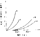
Fig. 2 is the graph of relation that is added in bias voltage and the electric current that passes through on the transferring roller at paper during by crack.
Fig. 3 is the sectional view of another kind of image forming of the present invention mechanism.
Shown in Figure 1 is a laser beam printer, and this is an a kind of typical image forming of the present invention mechanism.This mechanism comprises an electric photographic photosensitive spare 1, and for cylindric, along the rotation of arrow A direction, its axis normal is in drawing.An electrically conductive elastic transferring roller 2 is pressed on the photosensitive part 1, forms a video transfer station.When photosensitive part 1 lip-deep upward toner video arrived on the transfer station along with photosensitive part 1 rotation, the material for transfer (not shown) was transported to transfer station by transfer passage 4 along the arrow B direction when last toner video arrives.Add under the effect of shifting bias voltage with transferring roller 2 at power supply 3, last toner video is transferred on the material for transfer from photosensitive part.After the video transfering process was finished, the material for transfer that is loaded with the toner video continued to advance along the B direction, reaches photographic fixing workstation (not shown).
Around photosensitive part 1, be distributed with a primary charger 1a, be used to photosensitive part 1 surface to charge equably; A video information recorder is in order to recorded information on the surface of charging; A developer 1e delivers on the latent image in order to will go up toner 1f, forms the toner video by developer roll 1g; A clearer 1h removes residual last toner with a scraping blade 1i; An electric charge is removed lamp 1j, in order to remove residual electric charge; And other video forms the device that needs usefulness.The video information recorder comprises a semiconductor laser light source 1b, in order to produce the laser beam according to the video modulation; A polygon mirror 1c and a catoptron 1d.
Video forms mechanism and will be further specified.Photosensitive part 1 is an organic photoconductor photosensitive part, and its diameter is 30 millimeters.It is charged to-700 volts by primary charger.The laser beam of modulating by the form deflection of scanning is exposed the photosensitive part 1 of charging under video information, make the current potential of photosensitive part be reduced to-100 volts at it with the laser beam lithography part, forms electrostatic latent image at this.
This is right, and developer is supplied with the negative toner of going up of negative polarity charging, by anti-development, the toner video on forming corresponding to latent image on photosensitive part 1 surface of resembling.
When material for transfer arrives transfer station, add for the material for transfer back side by power supply 3 by transferring roller 2 and just shift bias voltage, the toner video is transferred on the material for transfer.
Transferring roller 2 comprises the metal mandrel 2a of 6 millimeters of diameters; The interior jacket layer 2b of ethylene-propylene-diethylene triamine terpolymer (EPDM) rubber system, its specific insulation is about 10
5Ohmcm; And the sheathcoat 2c of a Kynoar (PVDF) system, its thickness is 200 microns, specific insulation is 10
11Ohmcm.The external diameter of transferring roller 2 is 17 millimeters.
Fig. 2 is when the wide 21 centimetres transfer paper of A4 size (Japanese Industrial Standards) advances with the speed of 2.4 cels, biased relation curve on the metal mandrel 2a of transferring roller 2 and electric current between the power supply 3 and the transferring roller.The electric current of the paper that curve A represents to have the black real image during by transfer station; Curve B represents to have the electric current the when paper of video passes crack in vain entirely.
When the electric current of black real image is 0.5~1.0 microampere, can obtain best transfer efficiency, its value is not less than 70%, is not less than 80% in the time of preferably.
For example, when bias voltage was 2000 volts, the electric current that shifts the black real image between grid bias power supply and the transferring roller metal mandrel was 0.8 microampere, and this current value can make the video transfering process obtain satisfied effect, and the electric current of complete white video is 1.5 microamperes.
The transfer velocity of material for transfer is 2.4 cels, and the material for transfer width is 21 centimetres, and 0.8/ (2.4 * 21)=0.016 is 0.016 microcoulomb/square centimeter so be added in the electric weight at the video part back side; And 1.5/ (2.4 * 21)=0.030 is 0.030 microcoulomb/square centimeter so material for transfer does not have the added electric weight in the video part back side.In this case, last toner is not from there being the video part partly to spread to no video.
For comparison purpose, the high resistance Kynoar sheathcoat of above-mentioned transferring roller 2 is taken off, make it become a low resistance transferring roller, utilize it to carry out same experiment.
When bias voltage was 700 volts, black real image electric current was 0.8 microampere, and this moment, the video transfering process obtained satisfied effect.Yet for complete white video, electric current is 2.5 microamperes, and the result is having the electric weight that adds on video part and the no video part that very big difference is arranged, making toner partly spread no video part from video is arranged.
The electric weight that is added on the material for transfer back side is having video part different with no video part, to the result such as the following table of image quality and the evaluation of last toner diffusion:
Table have video part electric weight do not have on the video part electric weight toner diffusion (microcoulomb/centimetre
2) (microcoulomb/centimetre
2) degree
0.01 0.04 NG
0.01 0.03 NG
0.01 0.025 NG
0.01 0.2 F
0.01 0.017 G
0.01 G
0.02 0.08 NG
0.02 0.06 NG
0.02 0.05 NG
0.02 0.04 F
0.02 0.03 G
0.02 0.025 G
G: image quality is good, last toner indiffusion.
F: go up toner and spread slightly, but do not cause practical problems.
NG: go up toner and be diffused into the degree that to see for oneself, obviously reduced image quality.
By above-mentioned situation as seen, following formula if can be satisfied, the high-quality video of diffusion can be obtained not have.
A (coulomb/square centimeter) is added in the electric weight that material for transfer has the video part back side in A 〉=B/2 formula; B is the electric weight that is added in the no video part back side.
Find that also transferring roller sheathcoat specific insulation is preferably in 10
9~10
13Between the ohmcm, shift being biased between 1500 volts~3000 volts.
Fig. 3 is another embodiment, and its photosensitive part 1 is identical with previous embodiment.Transferring roller 5 comprises that the metal mandrel 5a of 6 millimeters of diameters and a resistivity are 10
10The conductive polyurethane jacket layer 5b of ohmcm, its external diameter is 17 millimeters.
In this structure, shift bias voltage and select 2500 volts for use.When the transfer paper in the crack had the black real image, electric current was 0.6 microampere, and when being the paper of complete white video, electric current is 1.0 microamperes.When the relation between the electric weight B of electric weight A that the video part is arranged and no video part can satisfy requiring of A 〉=B/2, last toner can partly not spread with no video from the video part is arranged certainly.
Using under the situation of this transferring roller, when the conductive jacket layer resistivity of transferring roller is 10
8~10
12Ohmcm when the transfer bias voltage is 1800 volts~3500 volts, can obtain good result.
In the above-described embodiments, translator adopts the form of transferring roller.Transferring roller can be driven by the drive unit of roller special use, also can be driven by photosensitive drum.
Other of translator may form be with shape in addition, do not move the scopiform of also not rotating, or conduction or low-resistance soft contact or friction device.
In the foregoing embodiments, to counter resemble to develop illustrate.And the present invention also can be used for common development or positive development, goes up toner during positive development and is deposited on the latent image part.In this case, the electric weight on the no video part that video part and supreme toner are arranged of toner in the deposit on the latent image satisfies above-mentioned requirements.
Image forming mechanism can be a kind of duplicating machine.Light is reflected by original copy and projects on the photosensitive part in this mechanism.
As mentioned above, higher part of the surface potential of electrostatic latent image and current potential can satisfy above requirement than the electric current of lower part by the contact-type translator after development.Like this, the electric weight of the noble potential of material for transfer part and electronegative potential part can avoid occurring excessive difference.Therefore, when material for transfer separates, can avoid harmful the moving of toner.
Like this, image quality can improve.
Above embodiment sets forth the present invention, but the present invention is not subjected to the restriction of above-mentioned details.The application will comprise for the purpose of improving or the improvement that may make in the scope of following claim and change.
Claims (9)
1. image forming mechanism, it comprises:
An image carrier (1), the last toner video that developed in order to carrying;
Transfer component (2,5) contacts with a surface away from the material for transfer of above-mentioned image carrier (1), in order to material for transfer is pressed on the image carrier of toner video, and add the transfer bias voltage, will go up the toner video and transfer on the material for transfer, it is characterized in that
Voltage is applied to transfer component (2,5) the bias voltage applicator (3) on, the electric weight A of unit area has been applied on toner and a part of material for transfer, the electric weight B of unit area is applied on a part of material for transfer of not going up toner, wherein electric weight A can not be less than B/2.
2. according to the described mechanism of claim 1, it is characterized in that transfer component comprises a rotatable members.
3. according to claim 1 or 2 described mechanisms, it is characterized in that transfer component comprises an elastic component.
4. according to the described mechanism of claim 1, it is characterized in that image carrier is an electric photographic photosensitive spare.
5. according to the described mechanism of claim 1, it is characterized in that it comprises that a latent image forms device, in order on image carrier, to form quiet latent image; A developer is in order to develop to the electrostatic latent image on the image carrier in the last toner video that has toner.
6. according to the described mechanism of claim 5, it is characterized in that latent image forms device and comprises one in order to charger and a device that applies optical information to image carrier to the image carrier uniform charging.
7. according to the described mechanism of claim 5, it is characterized in that above-mentioned developing mechanism develops to come the developing electrostatic latent image by anti-the elephant.
8. according to the described mechanism of claim 1, it is characterized in that a transfer component comprises that a volume resistivity is 10
8-10
12The skin of ohmcm.
9. according to the described mechanism of claim 8, it is characterized in that the voltage that is applied on the transfer component is 1800-3500 volts.
Applications Claiming Priority (2)
| Application Number | Priority Date | Filing Date | Title |
|---|---|---|---|
| JP271990/88 | 1988-10-29 | ||
| JP63271990A JP2733609B2 (en) | 1988-10-29 | 1988-10-29 | Transfer device |
Publications (2)
| Publication Number | Publication Date |
|---|---|
| CN1042427A CN1042427A (en) | 1990-05-23 |
| CN1031605C true CN1031605C (en) | 1996-04-17 |
Family
ID=17507614
Family Applications (1)
| Application Number | Title | Priority Date | Filing Date |
|---|---|---|---|
| CN89108196A Expired - Lifetime CN1031605C (en) | 1988-10-29 | 1989-10-28 | Transferring apparatus and image forming apparatus with transferring apparatus |
Country Status (6)
| Country | Link |
|---|---|
| US (1) | US5010370A (en) |
| EP (1) | EP0367157B1 (en) |
| JP (1) | JP2733609B2 (en) |
| KR (1) | KR930003617B1 (en) |
| CN (1) | CN1031605C (en) |
| DE (1) | DE68913903T2 (en) |
Families Citing this family (28)
| Publication number | Priority date | Publication date | Assignee | Title |
|---|---|---|---|---|
| EP0367245B1 (en) * | 1988-11-02 | 1996-01-03 | Canon Kabushiki Kaisha | An image forming apparatus |
| EP0428172B1 (en) * | 1989-11-16 | 1996-03-27 | Canon Kabushiki Kaisha | An image forming apparatus |
| JPH03170979A (en) * | 1989-11-30 | 1991-07-24 | Toshiba Corp | Image forming device |
| US5177537A (en) * | 1989-12-20 | 1993-01-05 | Canon Kabushiki Kaisha | Developing apparatus with elastic regulating member urged to a developer carrying member |
| JPH03211568A (en) * | 1990-01-17 | 1991-09-17 | Konica Corp | Color image forming device |
| US5150165A (en) * | 1990-04-10 | 1992-09-22 | Canon Kabushiki Kaisha | Image forming apparatus having image transfer member |
| US5159392A (en) * | 1990-04-23 | 1992-10-27 | Ricoh Company, Ltd. | Image forming apparatus for forming an image on one or both sides of a recording medium |
| JP2749953B2 (en) * | 1990-05-22 | 1998-05-13 | キヤノン株式会社 | Image forming device |
| US5387760A (en) * | 1990-10-19 | 1995-02-07 | Seiko Epson Corporation | Wet recording apparatus for developing electrostatic latent image |
| US5084735A (en) * | 1990-10-25 | 1992-01-28 | Eastman Kodak Company | Intermediate transfer method and roller |
| US5202729A (en) * | 1990-10-26 | 1993-04-13 | Canon Kabushiki Kaisha | Developing apparatus having a coated developing roller |
| DE69211912T2 (en) * | 1991-04-18 | 1996-11-21 | Hitachi Ltd | Electrophotographic recorder |
| US5284731A (en) * | 1992-05-29 | 1994-02-08 | Eastman Kodak Company | Method of transfer of small electrostatographic toner particles |
| US5303014A (en) * | 1992-11-20 | 1994-04-12 | Xerox Corporation | Biasable member having low surface energy |
| US5729810A (en) * | 1993-01-22 | 1998-03-17 | Xerox Corporation | Overcoated transfer roller for transferring developed images from one surface to another |
| JPH0736296A (en) * | 1993-07-01 | 1995-02-07 | Xerox Corp | Transfer roller device |
| US5732314A (en) * | 1993-11-26 | 1998-03-24 | Canon Kabushiki Kaisha | Image forming apparatus comprising image bearing member, intermediate image transfer member and secondary image transfer member for facilitating transfer of developed image from intermediate image transfer member to transfer material |
| ES2172557T3 (en) | 1994-08-08 | 2002-10-01 | Canon Kk | LOADING DEVICE AND DEVICE. |
| JP2984577B2 (en) * | 1995-01-25 | 1999-11-29 | キヤノン株式会社 | Image forming method |
| US5499085A (en) * | 1995-06-06 | 1996-03-12 | Moore Business Forms, Inc. | Trailing edge dust control |
| US5697015A (en) * | 1996-05-29 | 1997-12-09 | Lexmark International, Inc. | Electrophotographic apparatus and method for inhibiting charge over-transfer |
| US5873015A (en) * | 1997-02-18 | 1999-02-16 | Moore U.S.A. Inc. | Like polarity biasing to control toner dusting |
| US5970279A (en) * | 1997-06-02 | 1999-10-19 | Canon Kabushiki Kaisha | Image forming apparatus |
| JP2000131958A (en) | 1998-10-28 | 2000-05-12 | Sharp Corp | Transferring device |
| JP2000137391A (en) * | 1998-10-30 | 2000-05-16 | Ricoh Co Ltd | Image forming device of intermediate transfer system |
| JP2000352883A (en) | 1999-04-06 | 2000-12-19 | Canon Inc | Image forming device |
| US6859631B2 (en) * | 2002-08-30 | 2005-02-22 | Canon Kabushiki Kaisha | Image forming apparatus and image forming method |
| JP6192890B2 (en) * | 2011-11-25 | 2017-09-06 | 東芝三菱電機産業システム株式会社 | Surface potential distribution measuring apparatus and surface potential distribution measuring method |
Family Cites Families (21)
| Publication number | Priority date | Publication date | Assignee | Title |
|---|---|---|---|---|
| US3937572A (en) * | 1972-01-06 | 1976-02-10 | Bell & Howell Company | Apparatus for inductive electrophotography |
| US3788739A (en) * | 1972-06-21 | 1974-01-29 | Xerox Corp | Image compensation method and apparatus for electrophotographic devices |
| JPS5325436A (en) * | 1976-08-20 | 1978-03-09 | Minolta Camera Co Ltd | Fine line image reproducing method |
| US4326795A (en) * | 1978-10-14 | 1982-04-27 | Canon Kabushiki Kaisha | Image forming process and apparatus therefor |
| US4341457A (en) * | 1979-09-13 | 1982-07-27 | Canon Kabushiki Kaisha | Electrophotographic apparatus including an electrostatic separation device |
| US4402591A (en) * | 1979-09-29 | 1983-09-06 | Canon Kabushiki Kaisha | Electrophotographic apparatus |
| US4431301A (en) * | 1980-03-12 | 1984-02-14 | Tokyo Shibaura Denki Kabushiki Kaisha | Electrostatic copying apparatus with means for preventing contamination of reverse side of copying medium |
| JPS5767969A (en) * | 1980-10-16 | 1982-04-24 | Olympus Optical Co Ltd | Transcription device for electrophotographic copier for copying plural sheets |
| JPS58102967A (en) * | 1981-12-15 | 1983-06-18 | Fujitsu Ltd | Electrophotographic device |
| JPS6032077A (en) * | 1983-08-02 | 1985-02-19 | Canon Inc | Electrophotographic device |
| JPS60254061A (en) * | 1984-05-30 | 1985-12-14 | Ricoh Co Ltd | Electrostatic image recording device |
| US4728991A (en) * | 1984-09-19 | 1988-03-01 | Canon Kabushiki Kaisha | Image forming apparatus |
| JPS61267074A (en) * | 1985-05-21 | 1986-11-26 | Fuji Electric Co Ltd | Transfer device |
| JP2562296B2 (en) * | 1986-01-30 | 1996-12-11 | 三田工業株式会社 | Electrophotographic device using amorphous silicon |
| JPS6336281A (en) * | 1986-07-31 | 1988-02-16 | Ricoh Co Ltd | Electronic copying device |
| JPS6364068A (en) * | 1986-09-05 | 1988-03-22 | Ricoh Co Ltd | Electrostatic recorder |
| JPS63125952A (en) * | 1986-11-14 | 1988-05-30 | Minolta Camera Co Ltd | Large-quantity copying method |
| US4851960A (en) * | 1986-12-15 | 1989-07-25 | Canon Kabushiki Kaisha | Charging device |
| JPS63194283A (en) * | 1987-02-09 | 1988-08-11 | Canon Inc | Image forming device |
| JPS63296063A (en) * | 1987-05-28 | 1988-12-02 | Canon Inc | Image forming device |
| CN1038277C (en) * | 1987-12-28 | 1998-05-06 | 佳能公司 | Imaging device |
-
1988
- 1988-10-29 JP JP63271990A patent/JP2733609B2/en not_active Expired - Lifetime
-
1989
- 1989-10-24 US US07/426,002 patent/US5010370A/en not_active Expired - Lifetime
- 1989-10-27 DE DE68913903T patent/DE68913903T2/en not_active Expired - Fee Related
- 1989-10-27 EP EP89120039A patent/EP0367157B1/en not_active Expired - Lifetime
- 1989-10-28 KR KR1019890015565A patent/KR930003617B1/en not_active IP Right Cessation
- 1989-10-28 CN CN89108196A patent/CN1031605C/en not_active Expired - Lifetime
Also Published As
| Publication number | Publication date |
|---|---|
| JP2733609B2 (en) | 1998-03-30 |
| EP0367157A2 (en) | 1990-05-09 |
| KR930003617B1 (en) | 1993-05-08 |
| EP0367157B1 (en) | 1994-03-16 |
| EP0367157A3 (en) | 1991-08-14 |
| US5010370A (en) | 1991-04-23 |
| DE68913903T2 (en) | 1994-07-14 |
| DE68913903D1 (en) | 1994-04-21 |
| JPH02120779A (en) | 1990-05-08 |
| CN1042427A (en) | 1990-05-23 |
| KR910008508A (en) | 1991-05-31 |
Similar Documents
| Publication | Publication Date | Title |
|---|---|---|
| CN1031605C (en) | Transferring apparatus and image forming apparatus with transferring apparatus | |
| US5486909A (en) | Developing device for an image forming apparatus | |
| CN1341874A (en) | Image forming device | |
| EP0540341A2 (en) | Apparatus for and method of forming image | |
| CN1030484C (en) | process cartridge and image forming system | |
| US4999677A (en) | Imaging system with rigidizer | |
| CN1097876A (en) | Electrophotographic apparatus | |
| EP0400571A2 (en) | Recording apparatus | |
| EP0354310A1 (en) | Method and apparatus for electrophotographic printing | |
| US4205322A (en) | Electrostatic method of simultaneously transferring to a recording medium a toner image having different polarities | |
| US5561505A (en) | Mechanically sealable liquid charging apparatus | |
| CN1763658A (en) | Image forming apparatus | |
| EP0445208B1 (en) | Liquid developer based imaging machine and developer electrode therefor | |
| CN1164680A (en) | Conductive brush charging device | |
| JPS62280783A (en) | Liquid developing apparatus | |
| CN1143758A (en) | Image forming apparatus | |
| CN1472607A (en) | Method for cleaning transisting units and image forming device | |
| US4694310A (en) | Method and apparatus of electrophotography | |
| US5832346A (en) | Multi-point contact charging device | |
| US5563691A (en) | Image-forming apparatus | |
| EP0025671A1 (en) | Apparatus for developing an electrostatic latent image | |
| US5781833A (en) | Sealed liquid charging apparatus | |
| US4128328A (en) | Developing electrode type electrostatic copying machines | |
| EP0138376B1 (en) | Method and apparatus of electrophotography | |
| JPS6230432B2 (en) |
Legal Events
| Date | Code | Title | Description |
|---|---|---|---|
| C06 | Publication | ||
| C10 | Entry into substantive examination | ||
| PB01 | Publication | ||
| SE01 | Entry into force of request for substantive examination | ||
| C14 | Grant of patent or utility model | ||
| GR01 | Patent grant | ||
| C15 | Extension of patent right duration from 15 to 20 years for appl. with date before 31.12.1992 and still valid on 11.12.2001 (patent law change 1993) | ||
| OR01 | Other related matters | ||
| C17 | Cessation of patent right | ||
| CX01 | Expiry of patent term |
Granted publication date: 19960417 |