CN103117465A - Multifunctional connector - Google Patents
Multifunctional connector Download PDFInfo
- Publication number
- CN103117465A CN103117465A CN2013100597446A CN201310059744A CN103117465A CN 103117465 A CN103117465 A CN 103117465A CN 2013100597446 A CN2013100597446 A CN 2013100597446A CN 201310059744 A CN201310059744 A CN 201310059744A CN 103117465 A CN103117465 A CN 103117465A
- Authority
- CN
- China
- Prior art keywords
- metal
- terminal group
- pins
- insulating body
- seat
- Prior art date
- Legal status (The legal status is an assumption and is not a legal conclusion. Google has not performed a legal analysis and makes no representation as to the accuracy of the status listed.)
- Granted
Links
- 239000002184 metal Substances 0.000 claims abstract description 74
- NJPPVKZQTLUDBO-UHFFFAOYSA-N novaluron Chemical compound C1=C(Cl)C(OC(F)(F)C(OC(F)(F)F)F)=CC=C1NC(=O)NC(=O)C1=C(F)C=CC=C1F NJPPVKZQTLUDBO-UHFFFAOYSA-N 0.000 claims description 16
- 230000005540 biological transmission Effects 0.000 description 7
- 238000005516 engineering process Methods 0.000 description 2
- 230000009286 beneficial effect Effects 0.000 description 1
- 238000006243 chemical reaction Methods 0.000 description 1
- VJYFKVYYMZPMAB-UHFFFAOYSA-N ethoprophos Chemical compound CCCSP(=O)(OCC)SCCC VJYFKVYYMZPMAB-UHFFFAOYSA-N 0.000 description 1
- 230000008054 signal transmission Effects 0.000 description 1
- 229910000679 solder Inorganic materials 0.000 description 1
Images


Landscapes
- Details Of Connecting Devices For Male And Female Coupling (AREA)
Abstract
The invention relates to the technical field of signal connectors, in particular to a multifunctional connector which comprises a male seat and a female seat. The male seat and the female seat respectively comprise an insulating body, a plurality of metal terminals and a metal shell, the metal terminals are mounted on the insulating body, the metal shell is sleeved outside the insulating body, and the male seat and the female seat are respectively provided with thirteen metal pins. Thirteen pins needed by HDMI (high definition multimedia interface) technical protocol, five pins needed by MHL (mobile high-definition link) technical protocol and nine pins needed by USB3.0 technical protocol can be covered, the three technical protocols are unified to form a plug specification, electronic information equipment manufacturers can conveniently unify plugs, and cost caused by different joint specifications is reduced.
Description
Technical field
The present invention relates to the signal connector technical field, be specifically related to a kind of multifrnction connector.
Background technology
Signal connector is to connect two ones or two above electronic equipments, is used for the electronic device of handshaking transmission, has a wide range of applications in electronics and IT products.Nowadays, the use of electronics and IT products is quite general, and the annexation between electronics and IT products mainly relies on connector to realize.Usually have a plurality of conducting terminals in electric connector, and be electrically connected with solder terminal on circuit board, thereby realize the transmission of the signal of telecommunication.
HDMI (High Definition Multimedia Interface) (High Definition Multimedia Interface; HDMI) be a kind of digitized video/audio interfacing; it is the tailored version digital interface that is fit to image transmission; it can transmit audio and video frequency signal simultaneously; the maximum data transmission speed is 4.95Gb/s, need not simultaneously to transmit at signal advance capable D/A or mould/number conversion.At present, HDMI rely on to support audio frequency and video output, the advantages such as bandwidth that are enough to play the 1080p high-definition program is provided, and has widely in household electrical appliances and PC field and uses.The joint of HDMI1.4 version generally has the nineteen pin, wherein has four groups to be the pin that transmits for data-signal, and two every group, four groups totally eight.Also having three pins is to be used for specially doing controlling use, and these control signals comprise DDC (Display Data Channel) and consumer electronics control (Consumer Electronics Control, CEC).All the other are non-data-signal transmission pin, such as signal interference shielding pin, power pins, grounding pin etc.
USB3.0 is that the basis from USB2.0 develops, and has the data transmission bauds higher than USB2.0, is applied at present on a lot of novel electronic equipments.The USB3.0 interface is to have increased by five pins on original USB2.0 interface.
MHL (MOBILE HIGH-DEFINITION LINK) be again mobile high definition, and MHL can be applicable to mobile phone, PDA, digital camera, digital code camera, the equipment such as portable digital player.MHL is united a novel portable product video transmission agreement of proposal by many electronics goods producers.MHL not only can provide the high-definition audio and video signal, and has lower operating current, more and more is subject to the favor of electronics and IT products manufacturer.
The Micro-USB connector is a kind of less than standard USB and Mini-USB connector, more save the space-efficient signal connector, the digital products such as most mobile phone, MP4 all have this type of joint socket in the market, and Micro-USB can also use as charging plug transfer of data except being used for.
Yet, no matter be HDMI joint or USB3.0 joint, also or the MHL joint, all have the ad hoc structure of oneself.And along with kind and the function of electronics and IT products are more and more, do not have at present the AN connector of unified HDMI, a USB3.0, three kinds of connector functions of MHL, therefore numerous electronics and IT products manufacturers wishes to have a multifrnction connector of completing above-mentioned all function, and supports the Micro-USB plug of extensive use.
Summary of the invention
The object of the invention is to overcome above-described shortcoming, provide a kind of with HDMI, USB3.0, three kinds of functional connectors unifications of MHL, and support the multifrnction connector of Micro-USB plug.
For achieving the above object, concrete scheme of the present invention is as follows: multifrnction connector comprises male seat and female seat; Described male seat and female seat include respectively insulating body, be installed on a plurality of metal terminals on insulating body, be sheathed on the outer metal shell of insulating body; The metal terminal of described male seat is divided into first end subgroup and the second terminal group, and described first end subgroup is provided with five metal terminals, and described the second terminal group is provided with eight metal terminals; The metal terminal of described female seat is divided into the 3rd terminal group and the 4th terminal group, and described the 3rd terminal group corresponding matching first end subgroup is provided with five metal terminals, and described the 4th terminal group corresponding matching the second terminal group is provided with eight metal terminals.
Wherein, the insulating body of described female seat is T-shaped structure, and described the 3rd terminal group is located at the front end of the insulating body of described T-shaped structure, and described the 4th terminal group is located at the rear end of the insulating body of described T-shaped structure.
Wherein, described male seat also includes the pedestal that is arranged at the insulating body rear end, and pedestal is provided with a plurality of vertical type metal pins and a plurality of SMD metal pins.
Wherein, described vertical type metal pins is five, and with the corresponding electric connection of metal terminal of described first end subgroup, described SMD metal pins is eight, and with the corresponding electric connection of metal terminal of described the second terminal group.
Wherein, the metal shell outer surface of described male seat is provided with elastic card, and the metal shell inner surface of female seat is provided with the draw-in groove that cooperatively interacts with described elastic card.
Wherein, the both sides of described pedestal respectively are provided with a metal pin, and the metal shell of described metal pin and described male seat is electrically connected.
Wherein, the end face of described pedestal is provided with louvre.
Beneficial effect of the present invention is: the present invention can cover required nine the required pins of five pins, USB3.0 technical protocol of HDMI technical protocol required 13 pins, MHL technical protocol, thereby above-mentioned three kinds of technical protocols are unified, become a kind of plug standard, facilitate electronic message unit production firm that plug is unified, reduce because of the different costs that bring of joint specification.The insulating body of female seat is set as T-shaped structure, and can be used in conjunction with the Micro USB plug, make the present invention in the situation that do not use male seat of the present invention, also can use the Micro USB plug and carry out simple transfer of data and charging is used with the electronics and IT products of female seat.
Description of drawings
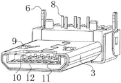
Fig. 1 is perspective view of the present invention;
Fig. 2 is the right stravismus perspective view of male seat of the present invention;
Fig. 3 is the left stravismus perspective view of male seat of the present invention;
Fig. 4 is the forward sight perspective view of female seat of the present invention;
Fig. 5 is the rear perspective structural representation of female seat of the present invention;
Description of reference numerals in Fig. 1 to Fig. 5: 1-male seat; 2-female seat; 3,16-metal shell; 4-pedestal; 5-louvre; 6-metal pin; 7-metal pins; 8-vertical type metal pins; 9-elastic card; 10-first end subgroup; The 11-the second terminal group; 12,13-insulating body; The 14-the four terminal group; The 15-the three terminal group; 17-SMD metal pins; The 18-the 1 pin; The 19-the 5 pin.
Embodiment
The present invention is further detailed explanation below in conjunction with the drawings and specific embodiments, is not the working of an invention scope is confined to this.
As shown in Fig. 1-5, the described multifrnction connector of the present embodiment comprises male seat 1 and female seat 2; Described male seat 1 and female seat 2 include respectively insulating body 12,13, be installed on a plurality of metal terminals on insulating body 12,13, be sheathed on insulating body 12,13 outer metal shells 3,16; The metal terminal of described male seat 1 is divided into first end subgroup 10 and the second terminal group 11, and described first end subgroup 10 is provided with five metal terminals, and described the second terminal group 11 is provided with eight metal terminals; The metal terminal of described female seat 2 is divided into the 3rd terminal group 15 and the 4th terminal group 14, and described the 3rd terminal group 15 corresponding matching first end subgroups 10 are provided with five metal terminals, and described the 4th terminal group 14 corresponding matching the second terminal group 11 are provided with eight metal terminals.Described female seat 2 rear ends are provided with a row totally ten three metal pins 7, and the corresponding electric connection of the metal terminal of female seat 2 front ends.
In the present embodiment, the present invention can the compatible with HDMI technical protocol, MHL technical protocol, USB3.0 technical protocol.The 4th terminal group 14 of female seat 2 is provided with eight metal terminals, can be divided into according to the difference of above-mentioned agreement the pin of difference in functionality respectively.
particularly, when the differential transfer technology of using HDMI, when using as HDMI technical protocol functional connector, eight pins of the 4th terminal group 14 can be set as the DATA0+ signal pins respectively, the DATA0-signal pins, the DATA1+ signal pins, the DATA1-signal pins, the DATA2+ signal pins, the DATA2-signal pins, DATA CLOCK+ signal pins, DATA CLOCK-signal pins, in five pins of the 3rd terminal group 15, the 1st pin 18 of the 3rd terminal group 15 is set as the GND grounding pin, the 5th pin 19 of the 3rd terminal group 15 is set as the VBUS power pins, its excess-three is individual as the control signal pin.The first end subgroup 10 of male seat 1 and the second terminal group 11 are set pinout accordingly with the 3rd terminal group 15 and the 4th terminal group 14 of female seat 2 respectively, thereby coordinate female seat 2 to use.
Particularly, when using the MHL technical protocol, when using as MHL technical protocol functional connector, five pins of the 3rd terminal group 15 will serve as respectively five required pins of MHL technical protocol, wherein, the 5th pin 19 that the 1st pin 18 of the 3rd terminal group 15 is set as GND grounding pin, the 3rd terminal group 15 is set as the VBUS power pins, and all the other are set as CBUS and control pin, D+ signal pins, D-signal pins.The first end subgroup 10 of male seat 1 and the second terminal group 11 are set pinout accordingly with the 3rd terminal group 15 and the 4th terminal group 14 of female seat 2 respectively, thereby coordinate female seat 2 to use.
particularly, when using the USB3.0 technical protocol, when using as USB3.0 technical protocol functional connector, the 1st pin 18 and the 5th pin 19, and any two pins in other three pins of the 3rd terminal group 15 and any five pins in the 4th terminal group 14 will serve as respectively needed nine pins of USB3.0 technical protocol, wherein, the 1st pin 18 of the 3rd terminal group 15 is set as the GND grounding pin, the 5th pin 19 of the 3rd terminal group 15 is set as the VBUS power pins, any two pins in three pins of other of the 3rd terminal group 15 are set as the D+ signal pins, the D-signal pins.Selecting arbitrarily five pins in the 4th terminal group 14 is set as respectively two RX and receives signal pins, two TX transmitted signal pins, the empty pin of NC.The first end subgroup 10 of male seat 1 and the second terminal group 11 are set pinout accordingly with the 3rd terminal group 15 and the 4th terminal group 14 of female seat 2 respectively, thereby coordinate female seat 2 to use.
Micro USB has been widely used in most of electronics and IT products, female seat 2 for can and Micro USB joint be used in conjunction with, the insulating body 13 of female seat 2 of the present invention is T-shaped structure, wherein the 3rd terminal group 15 is located at the front end of the insulating body 13 of described T-shaped structure, and the 4th terminal group 14 is located at the rear end of the insulating body 13 of described T-shaped structure, the structure size of the front end of the insulating body 13 of described T-shaped structure can be used in conjunction with the Micro USB plug, the 1st pin 18 of the 3rd terminal group 15 is set as the GND grounding pin, the 5th pin 19 of the 3rd terminal group 15 is set as the VBUS power pins, all the other are also corresponding with Micro USB pin, thereby make female seat 2 to be used in conjunction with Micro USB, namely ought not use in male seat 1 situation of the present invention, also can use the Micro USB plug and carry out simple transfer of data and charging is used with the electronics and IT products of female seat 2.
In the present embodiment, described male seat 1 include be arranged at insulating body 12 rear ends, be used for being fixed on the pedestal 4 on pcb board, in order to improve space availability ratio,, pedestal 4 is provided with a plurality of vertical type metal pins 8 and a plurality of SMD metal pins 17.Wherein, described vertical type metal pins 8 is five, and with the corresponding electric connection of metal terminal of described first end subgroup 10, described SMD metal pins 17 is eight, and with the corresponding electric connection of metal terminal of described the second terminal group 11.
In the present embodiment, metal shell 3 outer surfaces of described male seat 1 are provided with elastic card 9, and metal shell 16 inner surfaces of female seat 2 are provided with the draw-in groove that cooperatively interacts with described elastic card 9.When pegging graft, the front end of elastic card 9 is pressed down by the metal shell 16 of female seat 2, and slide in the corresponding draw-in groove of female seat 2, after in sliding into the corresponding draw-in groove of female seat 2, elastic card 9 is upspring, and makes male seat 1 and female seat 2 fixing, when extracting, the rear end of elastic card 9 is pressed down by the metal shell 16 of female seat 2, and skids off the corresponding draw-in groove of female seat 2, just male seat 1 can be extracted.Elastic card 9 is set, can makes male seat 1 and female seat 2 more firm when pegging graft, difficult drop-off.
In the present embodiment, the metal shell 3 of male seat 1 is generally used for signal interference shielding circuit and uses, the both sides of described pedestal 4 respectively are provided with a metal pin 6, described metal pin 6 is electrically connected with the metal shell 3 of described male seat 1, metal pin 6 is set plays male seat 1 is welded on pcb board, can also facilitate manufacturer that the signal interference shielding is connected on pcb board.In addition, the end face of described pedestal 4 is provided with louvre 5, and the heat that produces in the time of can be easily with signal transmission distributes from male seat 1.
The above is only a preferred embodiment of the present invention, therefore all equivalences of doing according to the described structure of patent claim of the present invention, feature and principle change or modify, is included in the protection range of patent application of the present invention.
Claims (7)
1. a multifrnction connector, comprise male seat (1) and female seat (2); Described male seat (1) and female seat (2) include respectively insulating body (12,13), be installed on a plurality of metal terminals on insulating body (12,13), be sheathed on the outer metal shell (3,16) of insulating body (12,13); It is characterized in that: the metal terminal of described male seat (1) is divided into first end subgroup (10) and the second terminal group (11), and described first end subgroup (10) is provided with five metal terminals, and described the second terminal group (11) is provided with eight metal terminals; The metal terminal of described female seat (2) is divided into the 3rd terminal group (15) and the 4th terminal group (14), described the 3rd terminal group (15) corresponding matching first end subgroup (10) is provided with five metal terminals, and described the 4th terminal group (14) corresponding matching the second terminal group (11) is provided with eight metal terminals.
2. a kind of multifrnction connector according to claim 1, it is characterized in that: the insulating body (13) of described female seat (2) is T-shaped structure, described the 3rd terminal group (15) is located at the front end of the insulating body (13) of described T-shaped structure, and described the 4th terminal group (14) is located at the rear end of the insulating body (13) of described T-shaped structure.
3. a kind of multifrnction connector according to claim 1, it is characterized in that: described male seat (1) also includes the pedestal (4) that is arranged at insulating body (12) rear end, and pedestal (4) is provided with a plurality of vertical type metal pins (8) and a plurality of SMD metal pins (17).
4. a kind of multifrnction connector according to claim 3, it is characterized in that: described vertical type metal pins (8) is five, and with the corresponding electric connection of metal terminal of described first end subgroup (10), described SMD metal pins (17) is eight, and with the corresponding electric connection of metal terminal of described the second terminal group (11).
5. a kind of multifrnction connector according to claim 1, it is characterized in that: metal shell (3) outer surface of described male seat (1) is provided with elastic card (9), and metal shell (16) inner surface of female seat (2) is provided with the draw-in groove that cooperatively interacts with described elastic card (9).
6. a kind of multifrnction connector according to claim 3, it is characterized in that: the both sides of described pedestal (4) respectively are provided with a metal pin (6), and described metal pin (6) is electrically connected with the metal shell (3) of described male seat (1).
7. a kind of multifrnction connector according to claim 3, it is characterized in that: the end face of described pedestal (4) is provided with louvre (5).
Priority Applications (1)
| Application Number | Priority Date | Filing Date | Title |
|---|---|---|---|
| CN201310059744.6A CN103117465B (en) | 2013-02-26 | 2013-02-26 | A kind of multifrnction connector |
Applications Claiming Priority (1)
| Application Number | Priority Date | Filing Date | Title |
|---|---|---|---|
| CN201310059744.6A CN103117465B (en) | 2013-02-26 | 2013-02-26 | A kind of multifrnction connector |
Publications (2)
| Publication Number | Publication Date |
|---|---|
| CN103117465A true CN103117465A (en) | 2013-05-22 |
| CN103117465B CN103117465B (en) | 2015-09-30 |
Family
ID=48415775
Family Applications (1)
| Application Number | Title | Priority Date | Filing Date |
|---|---|---|---|
| CN201310059744.6A Active CN103117465B (en) | 2013-02-26 | 2013-02-26 | A kind of multifrnction connector |
Country Status (1)
| Country | Link |
|---|---|
| CN (1) | CN103117465B (en) |
Cited By (5)
| Publication number | Priority date | Publication date | Assignee | Title |
|---|---|---|---|---|
| CN104600774A (en) * | 2014-12-05 | 2015-05-06 | 深圳天珑无线科技有限公司 | Charging recognition circuit, charging recognition method, data line and mobile terminal |
| CN105247739A (en) * | 2014-05-07 | 2016-01-13 | 华为终端有限公司 | Plug and connector module |
| CN105449474A (en) * | 2014-09-19 | 2016-03-30 | 鸿庆鑫电声科技有限公司 | Electric connector, connecting device with the same, and connecting assembly with the electric connector |
| CN107273313A (en) * | 2014-06-09 | 2017-10-20 | 青岛海信移动通信技术股份有限公司 | The USB mode of USB interface and the compatibility method and device of MHL patterns |
| CN111803081A (en) * | 2019-03-12 | 2020-10-23 | 疆域康健创新医疗科技成都有限公司 | Physiological parameter monitoring device and medical equipment with same |
Citations (8)
| Publication number | Priority date | Publication date | Assignee | Title |
|---|---|---|---|---|
| CN201656181U (en) * | 2010-02-05 | 2010-11-24 | 咏贻国际有限公司 | Conducted contact structure of connector |
| CN201708350U (en) * | 2010-06-25 | 2011-01-12 | 诠欣股份有限公司 | Electric connector |
| US20110059656A1 (en) * | 2009-09-04 | 2011-03-10 | Chou Hsien Tsai | Electrical connector and terminal structure thereof |
| CN201838751U (en) * | 2010-08-11 | 2011-05-18 | 东莞市泰康电子科技有限公司 | HDMI (High-Definition Multimedia Interface) connector |
| CN201898259U (en) * | 2010-09-30 | 2011-07-13 | 广迎工业股份有限公司 | Improved structure of all-in-one connector |
| CN202067988U (en) * | 2010-09-29 | 2011-12-07 | 蔡周贤 | Electric connecting socket |
| CN202121180U (en) * | 2011-04-29 | 2012-01-18 | 泰科电子(上海)有限公司 | Plug connector and connector assembly |
| CN203071273U (en) * | 2013-02-26 | 2013-07-17 | 周法勇 | Multifunctional connector |
-
2013
- 2013-02-26 CN CN201310059744.6A patent/CN103117465B/en active Active
Patent Citations (8)
| Publication number | Priority date | Publication date | Assignee | Title |
|---|---|---|---|---|
| US20110059656A1 (en) * | 2009-09-04 | 2011-03-10 | Chou Hsien Tsai | Electrical connector and terminal structure thereof |
| CN201656181U (en) * | 2010-02-05 | 2010-11-24 | 咏贻国际有限公司 | Conducted contact structure of connector |
| CN201708350U (en) * | 2010-06-25 | 2011-01-12 | 诠欣股份有限公司 | Electric connector |
| CN201838751U (en) * | 2010-08-11 | 2011-05-18 | 东莞市泰康电子科技有限公司 | HDMI (High-Definition Multimedia Interface) connector |
| CN202067988U (en) * | 2010-09-29 | 2011-12-07 | 蔡周贤 | Electric connecting socket |
| CN201898259U (en) * | 2010-09-30 | 2011-07-13 | 广迎工业股份有限公司 | Improved structure of all-in-one connector |
| CN202121180U (en) * | 2011-04-29 | 2012-01-18 | 泰科电子(上海)有限公司 | Plug connector and connector assembly |
| CN203071273U (en) * | 2013-02-26 | 2013-07-17 | 周法勇 | Multifunctional connector |
Cited By (7)
| Publication number | Priority date | Publication date | Assignee | Title |
|---|---|---|---|---|
| CN105247739A (en) * | 2014-05-07 | 2016-01-13 | 华为终端有限公司 | Plug and connector module |
| US9711877B2 (en) | 2014-05-07 | 2017-07-18 | Huawei Device Co., Ltd. | Plug and connector module |
| CN105247739B (en) * | 2014-05-07 | 2018-08-21 | 华为终端有限公司 | A kind of plug and connector module |
| CN107273313A (en) * | 2014-06-09 | 2017-10-20 | 青岛海信移动通信技术股份有限公司 | The USB mode of USB interface and the compatibility method and device of MHL patterns |
| CN105449474A (en) * | 2014-09-19 | 2016-03-30 | 鸿庆鑫电声科技有限公司 | Electric connector, connecting device with the same, and connecting assembly with the electric connector |
| CN104600774A (en) * | 2014-12-05 | 2015-05-06 | 深圳天珑无线科技有限公司 | Charging recognition circuit, charging recognition method, data line and mobile terminal |
| CN111803081A (en) * | 2019-03-12 | 2020-10-23 | 疆域康健创新医疗科技成都有限公司 | Physiological parameter monitoring device and medical equipment with same |
Also Published As
| Publication number | Publication date |
|---|---|
| CN103117465B (en) | 2015-09-30 |
Similar Documents
| Publication | Publication Date | Title |
|---|---|---|
| US10714875B2 (en) | Electrical receptacle connector | |
| US8696218B2 (en) | Optoelectronic signal conversion module | |
| US20130217274A1 (en) | Connector for achieving complete interoperability between different types of data and multimedia interfaces | |
| US8886852B2 (en) | Techniques for achieving complete interoperability between different types of data and multimedia interfaces in handheld devices | |
| US8550856B2 (en) | Transfer plug assembly | |
| US9153923B2 (en) | USB power adapter with integrated male and female connectors to charge and sync functions | |
| CN103117465B (en) | A kind of multifrnction connector | |
| US7988460B1 (en) | Electrical engagement structure of connection device | |
| KR20160001267A (en) | Connector plug and connector socket | |
| CN212784017U (en) | Socket connecting device and plug connecting device | |
| US20130323951A1 (en) | Adaptor for connecting connectors with different interfaces | |
| CN203071273U (en) | Multifunctional connector | |
| CN203895655U (en) | Mini-sized USB connector capable of being plugged in forward and backward directions | |
| US20070072491A1 (en) | Integrated signal connecting port | |
| CN200941481Y (en) | Plug connector | |
| US20150044894A1 (en) | Usb/mini usb convertible connector | |
| TWM460427U (en) | Electrical connector plug | |
| CN104577382A (en) | Data signal communication connection device | |
| CN202204963U (en) | Photoelectric signal transforming module | |
| US8690458B2 (en) | Optical connector | |
| EP2976873B1 (en) | Interconnect assembly | |
| JP3169392U (en) | connector | |
| CN105633748A (en) | Special peripheral communication cable connection device for computer data transmission | |
| CN202127115U (en) | Combination type universal sequence bus connector | |
| CN203800334U (en) | Slide-connection-type connector, slide-connection-type connecting base and electronic device used for connector |
Legal Events
| Date | Code | Title | Description |
|---|---|---|---|
| C06 | Publication | ||
| PB01 | Publication | ||
| C10 | Entry into substantive examination | ||
| SE01 | Entry into force of request for substantive examination | ||
| C14 | Grant of patent or utility model | ||
| GR01 | Patent grant | ||
| C41 | Transfer of patent application or patent right or utility model | ||
| TR01 | Transfer of patent right |
Effective date of registration: 20161230 Address after: Changan Town, Guangdong city of Dongguan province in spring 523000 Road Industrial Zone No. 2 Dongguan Zhongzhou Electronics Co. Ltd Patentee after: Dongguan City Zhong Zhou Electronic Ltd. Address before: Changan Town, Guangdong city of Dongguan Province spring 523000 Yong Tau Industrial Area Dongguan Road, Zhongzhou Electronics Co. Ltd. Patentee before: Zhou Fayong |