A kind of high-voltage switch contact temperature rise on-line monitoring method
Technical field
The present invention relates to a kind ofly utilize wireless radio-frequency on-line monitoring high-voltage switch contact contact temperature rise situation, and then to the high-voltage switch contact diagnosing malfunction, ensure circuit and the method thereof of the safe operation of electric system.
Background technology
In order to guarantee the safe operation of electric system, the electric system thermal fault detection is subject to people's generally attention, high voltage bus is when the contact of running overload or high-voltage switch gear is bad, because contact resistance becomes large, produce fever phenomenon in the out-of-date meeting of load current flow, this fever phenomenon causes that insulation ag(e)ing even punctures, thereby causes short circuit, form major accident, cause heavy economic losses.
In the electric power system that adopts the power cable power transmission and distribution, there is statistics to show, the cable operation troubles more than 90% is caused by joint fault, and the joint contact resistance becomes greatly, overload etc. causes that connector temperature is too high, is the main cause of initiating failure.The investigation of Beijing DianKeYuan and statistics show: in whole nineties Power System in China distribution voltage level switch accident, the temperature rise fault accounts for 8.9%, therefore, detect and monitor the temperature of high-voltage switch gear contact, bus and high-voltage cable joint, find in advance and get rid of hot stall hidden danger, the safe and reliable operation of electric system is had very important significance.
For the research of this respect technology, whether contact with measurand according to sensor both at home and abroad, be divided into two kinds of methods of contact temperature-measuring and contactless temperature-measuring.Contactless temperature-measuring method adopts the thermal infrared detection technique, it is to exist certain funtcional relationship to make between radiation intensity relative to object and temperature, its advantage is that measurement range is large, accuracy is high, but there is significant limitation in the restriction due to visual angle and the distance coefficient of instrument own in actual applications, the another one shortcoming of infrared thermometer is to need manual inspection, sometimes also can receive the impact of the factors such as weather, it can't detect the high-voltage switch gear contact that is enclosed in rack, can't realize that high-tension apparatus and temperature online detect integrated.the contact temperature-measuring method is many, mainly contain following several: (1) colour temperature sheet method, adopt color chips (claiming that also temperature indicating records label), its be heated a series of chemistry of rear generation and physical change are by the change of molecular structure, cause catoptrical color to change, can judge temperature according to its color, shortcoming is that accuracy is low, poor reliability, can not carry out quantitative measurment, and concerning high-voltage switch gear contact etc., almost cannot see color during operation in the sealing rack, (2) Fiber Optic Pyrometer, U.S. Lu Ke company is under the subsidy of American Electric Power research institute (EPRI), developed and aimed at the electric system application and the fluorescence fiber temperature measurement device of Development and Production monitoring Transformer Winding temperature, this is a kind of technology of brand-new on-line monitoring high voltage electric equipment internal temperature, optical fiber has good electrical insulation properties and anti-electromagnetic interference capability, probe can be embedded in simultaneously the selected position of high pressure of power equipment inside, directly measure the actual temperature change of this point, but optic fiber thermometer is expensive, the installation of optic fiber thermometer and transform cumbersome, the insulation ag(e)ing of optical fiber after long-time running, cause the mutual breakdown problem of high and low pressure side, Fiber Optic Pyrometer is not yet promoted the use of at home, (3) other contact thermography: domesticly multiple online contact temperature-measuring scheme also occurred, mainly that temperature sensor is arranged on switch contact, by wireless radio-frequency or intensity modulation technology, temperature signal is delivered to ground, then by ground-based computer, temperature signal is processed, how these schemes all exist without exception to the problem of temperature sensor power supply, and following several power supply mode (1) battery method is arranged usually: disadvantage can't guarantee at whole high-pressure side normal power supply of non-turn(a)round, (2) photoelectric cell method: the high-pressure side sensor uses silicon photocell, provide light source by the low pressure side, thereby it is electric that sensor is got, and shortcoming is be difficult for installing and install rear due to the on high-tension side phase insulation of the excessive impact of silicon photocell area, (3) low-pressure side power supply: shortcoming is the potential possibility that exists the mutual feed of low-pressure side and high-pressure side and puncture.
Summary of the invention
Technical matters to be solved by this invention is to provide a kind of external power supply that do not need, but utilize the large electric current that high-voltage switch gear flows through to obtain the device of a kind of on-line monitoring high-voltage switch contact contact temperature rise of Power supply electric energy by electromagnetic coupled, utilize wireless radio-frequency and then to the high-voltage switch contact diagnosing malfunction, ensure the method for the safe operation of electric system.
For achieving the above object, the technical scheme that adopts is:
A kind of high-voltage switch contact temperature rise on-line monitoring method is characterized in that:
1, the equipment that adopts is a kind of high-voltage switch contact temperature rise on-Line Monitor Device of the present invention, comprises the microprocessor of radiating portion power circuit, temperature collection circuit, radiating portion microprocessor, radio transmitter, wireless receiving circuit, receiving unit, display circuit and the receiving unit power circuit of receiving unit.
The radiating portion power circuit is comprised of electric current inductive coil, annular core and voltage transformation module.
The electric current inductive coil is on annular core, the concrete number of turns needs to determine by a certain percentage according to tested current value size, two lead-in wires of electric current inductive coil are connected with the corresponding wiring terminal of voltage transformation module, and voltage transformation module is rectification, filtering, voltage stabilizing circuit module.The voltage output end of voltage transformation module is connected voltage input end with temperature collection circuit, radiating portion microprocessor respectively and is connected with radio transmitter.
The temperature signal output terminal of temperature collection circuit is connected with the temperature signal input interface of the microprocessor of radiating portion; The signal output part of the microprocessor of radiating portion is connected with the signal input part of radio transmitter.
The power circuit of receiving unit is rectification, filtering, mu balanced circuit, by ac power supply or directly battery-powered, for the display circuit of wireless receiving circuit, receiving unit microprocessor and receiving unit provides power supply.The temperature signal output terminal of wireless receiving circuit is connected with the temperature signal input end of the microprocessor of receiving unit, and the temperature signal output terminal of the microprocessor of receiving unit is connected with the corresponding interface of the display circuit of receiving unit.
In temperature collection circuit, the collection of temperature can be adopted digital temperature sensor AD590, LM92, also can adopt thermistor (for example 10K Ω, 35K Ω) to complete; The microprocessor of radiating portion microprocessor and receiving unit is selected PIC, NSP430,51 or AVR series etc., the wireless transmit of radio transmitter and wireless receiving circuit and the rf frequency of wireless receiving are selected integration module MAX1479, MAX7030 or MAX7031 in the 315-960MHZ scope; The wireless technology of utilizing high pressure temperature monitoring end and Displaying Meter end has realized isolation fully, and the microprocessor of receiving unit leaves wireless (GPRS) and wired (485 or 232) interface circuit.
2, high-voltage switch contact temperature rise on-line monitoring method:
after being sealed with insulating material, the ring-type iron core is sleeved on tested switch contact conductor, when high-voltage contact has electric current to pass through like this, just be coupled out the large electric current that is flow through by switch contact in the electric current inductive coil, the voltage transformation module of two lead-in wires by being attached thereto of electric current inductive coil output terminal, be embodied as temperature collection circuit, radiating portion microprocessor and radio transmitter provide power supply, the radiating portion power supply not needing to have realized external power supply, utilize the electromagnetic field couples principle directly to obtain energy on high voltage bus and provide electric energy for collector, solved conventional batteries power supply replacement difficulty, sometimes the problem that can't change, simultaneously owing to adopting little CT and magnetic saturation technology to make the radiating portion power circuit realize that wider range of current 50A-5000A all can provide stable voltage.temperature collection circuit is realized the collection of temperature by digital temperature sensor or thermistor, temperature collection circuit is delivered to the radiating portion microprocessor with the temperature signal of the contact contact that collects and is processed, deliver to radio transmitter after temperature signal modulation after the radiating portion microprocessor will be processed, wireless transmit adopts the emission of open frequency range micropower can not produce interference to miscellaneous equipment, realized that simultaneously high pressure temperature monitoring end and Displaying Meter end isolate fully, wireless receiving circuit is delivered to the microprocessor processes of receiving unit after with the temperature signal demodulation that receives, the display circuit that temperature value after the microprocessor of receiving unit will be processed is delivered to receiving unit shows, based on the high-voltage switch contact temperature rise on-line monitoring circuit temperature collecting part of wireless radio-frequency poured with epoxy resin switch contacts (for example round contact or flat contact) with applicable different size in the fixture external member of different size.
The present invention has positive effect: in (1) high-voltage switch contact temperature rise on-line monitoring circuit based on wireless radio-frequency of the present invention, adopt little CT and magnetic saturation technology to make the radiating portion power circuit realize that wider range of current 50A-5000A all can provide stable operating voltage.(2) the high-voltage switch contact temperature rise on-line monitoring circuit wireless transmit based on wireless radio-frequency of the present invention adopts the emission of open frequency range micropower can not produce interference to miscellaneous equipment, has realized that simultaneously high pressure temperature monitoring end and Displaying Meter end isolate fully.(3) the high-voltage switch contact temperature rise on-line monitoring circuit based on wireless radio-frequency of the present invention, temperature acquisition partly are cast in the interior switch contacts with applicable different size of fixture external member (for example round contact or flat contact) of different size.
Description of drawings
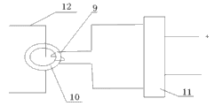
Fig. 1 is the temperature acquisition part schematic diagram of embodiment 1.
Fig. 2 is the schematic diagram that the temperature display section of embodiment 1 divides.
Fig. 3 is the schematic diagram of the radiating portion power circuit of embodiment 1.
Embodiment
A kind of high-voltage switch contact temperature rise on-line monitoring method is characterized in that:
1, the on-line monitoring equipment that adopts is high-voltage switch contact temperature rise on-Line Monitor Device, comprises the microprocessor 6 of radiating portion power circuit 1, temperature collection circuit 2, radiating portion microprocessor 3, radio transmitter 4, wireless receiving circuit 5, receiving unit, display circuit 7 and the receiving unit power circuit 8 of receiving unit.
Radiating portion power circuit 1 is comprised of electric current inductive coil 9, annular core 10 and voltage transformation module 11,9 windings of electric current inductive coil are on annular core 10, two lead-in wires of electric current inductive coil 9 are connected with the corresponding wiring terminal of voltage transformation module 11, and the voltage output end of voltage transformation module 11 is connected with the voltage input end that temperature collection circuit 2, radiating portion microprocessor 3 are connected with radio transmitter respectively.The temperature signal output terminal of temperature collection circuit 2 is connected with the temperature signal input interface of the microprocessor 3 of radiating portion.The temperature signal output terminal of the microprocessor 3 of radiating portion is connected with the signal input interface of radio transmitter 4.
The voltage output end of receiving unit power circuit 8 is connected the voltage input interface of display circuit 7 with the microprocessor 6 of wireless receiving circuit 5, receiving unit respectively and is connected with receiving unit.The temperature signal output terminal of wireless receiving circuit 5 is connected with the temperature signal input interface of the microprocessor 6 of receiving unit, and the temperature signal output terminal of the microprocessor 6 of receiving unit is connected with the signal input interface of the display circuit 7 of receiving unit.
2, high-voltage switch contact temperature rise on-line monitoring:
Be sleeved on the conductor 12 of tested switch contact after annular core 10 use insulating material sealings, be coupled out the electric current that tested switch contact flows through in electric current inductive coil 9, electric current inductive coil 9 provides stabilized voltage supply by microprocessor 3 and the radio transmitter 4 that voltage transformation module 11 is respectively temperature collection circuit 2, radiating portion, range of current is 50A-5000A, and the radiating portion power circuit can also charge for reserve battery simultaneously.The temperature signal that temperature collection circuit 2 collects is delivered to radiating portion microprocessor 3 and is processed, deliver to radio transmitter 4 after temperature signal modulation after radiating portion microprocessor 3 will be processed, wireless receiving circuit 5 receives the temperature signal that radio transmitter 4 sends, delivering to the microprocessor 6 of receiving unit after demodulation processes, and the display 7 that the temperature signal after processing is delivered to receiving unit in real time shows, completes high-voltage switch contact temperature rise on-line monitoring.
In temperature collection circuit, digital temperature sensor AD590 or LM92 are adopted in the collection of temperature, or adopt thermistor 10K Ω or 35K Ω to complete; The microprocessor of radiating portion microprocessor and receiving unit is selected PIC, NSP430,51 or AVR, the wireless transmit of radio transmitter and wireless receiving circuit and the rf frequency of wireless receiving are selected integration module MAX1479, MAX7030 or MAX7031 in the 315-960MHz scope; The wireless technology of utilizing high pressure temperature monitoring end and Displaying Meter end has realized isolation fully, and the microprocessor of receiving unit leaves wireless GPRS interface circuit and wired 485 or 232 interface circuits.