CN102948257B - Fault protected current source for lighting element testing - Google Patents
Fault protected current source for lighting element testing Download PDFInfo
- Publication number
- CN102948257B CN102948257B CN201180029223.5A CN201180029223A CN102948257B CN 102948257 B CN102948257 B CN 102948257B CN 201180029223 A CN201180029223 A CN 201180029223A CN 102948257 B CN102948257 B CN 102948257B
- Authority
- CN
- China
- Prior art keywords
- current
- output
- processor
- electric current
- voltage
- Prior art date
- Legal status (The legal status is an assumption and is not a legal conclusion. Google has not performed a legal analysis and makes no representation as to the accuracy of the status listed.)
- Active
Links
Images


Classifications
-
- H—ELECTRICITY
- H05—ELECTRIC TECHNIQUES NOT OTHERWISE PROVIDED FOR
- H05B—ELECTRIC HEATING; ELECTRIC LIGHT SOURCES NOT OTHERWISE PROVIDED FOR; CIRCUIT ARRANGEMENTS FOR ELECTRIC LIGHT SOURCES, IN GENERAL
- H05B45/00—Circuit arrangements for operating light-emitting diodes [LED]
- H05B45/50—Circuit arrangements for operating light-emitting diodes [LED] responsive to malfunctions or undesirable behaviour of LEDs; responsive to LED life; Protective circuits
-
- Y—GENERAL TAGGING OF NEW TECHNOLOGICAL DEVELOPMENTS; GENERAL TAGGING OF CROSS-SECTIONAL TECHNOLOGIES SPANNING OVER SEVERAL SECTIONS OF THE IPC; TECHNICAL SUBJECTS COVERED BY FORMER USPC CROSS-REFERENCE ART COLLECTIONS [XRACs] AND DIGESTS
- Y02—TECHNOLOGIES OR APPLICATIONS FOR MITIGATION OR ADAPTATION AGAINST CLIMATE CHANGE
- Y02B—CLIMATE CHANGE MITIGATION TECHNOLOGIES RELATED TO BUILDINGS, e.g. HOUSING, HOUSE APPLIANCES OR RELATED END-USER APPLICATIONS
- Y02B20/00—Energy efficient lighting technologies, e.g. halogen lamps or gas discharge lamps
- Y02B20/30—Semiconductor lamps, e.g. solid state lamps [SSL] light emitting diodes [LED] or organic LED [OLED]
Landscapes
- Dc-Dc Converters (AREA)
- Emergency Protection Circuit Devices (AREA)
Abstract
A fault protected current source is provided that can be used to safely drive LEDs in reliability test systems. The current source is includes circuits and processes that detect the common faults found in LED reliability test systems. After a fault is detected, the current source shuts down drive before destructive spikes are produced. Because only true LED failures are counted, this fault protected current source can be used to construct reliability test systems that produce more accurate reliability test data.
Description
The cross reference of related application
The application requires U.S. Provisional Application No.61/282,870 rights and interests, and this application is filed on April 14th, 2010, and its full content merges to this by reference.
Technical field
The present invention relates in general to electric test equipment, and more particularly, some embodiment relate to the current source for semiconductor lighting element.
Background technology
Light-emitting diode (LED) thus reliability testing often carry out the performance that assessment device is passed in time.These tests make LED stand the temperature and humidity level that rising exceedes point of normal operation.These harsh conditions have been accelerated the normal aging process of LED material.This within the rational time (operation that normally hundreds of arrives several thousand hours) produces and lost efficacy.Even now is measured, but failure rate still can be lower, thereby and must test a large amount of devices and collect enough data, to guarantee significant conclusion in statistics.
At long-term reliability test period, LED is often by the direct current (DC) or the pulse power supply power supply that are called current source.In order to test, levels of current can be set to the normal running level higher than device, thereby LED is improved to pressure.LED current source is the critical component of reliability test system.They must provide to LED the drive current of correct level, so that reliability testing operation thousands of hours.Although this may seem only to require high reliability circuit design, many true fault conditions can increase the weight of current source burden at these marathon test periods.If current source is to carry very little electric current to respond these faults, LED is driven in incorrect, less stress level so.But if current source responds to produce super-high-current, LED will be by overvoltage so, thereby has reduced its life-span, and sometimes causes catastrophic inefficacy.Under arbitrary circumstances in these circumstances, can make reliability testing give a discount or destroy, and can be lost in the time of dropping in test.
In order to minimize the number of the current source needing, LED is often arranged to series circuit, and it is powered by single current source.LED is placed in load board, provides on the circuit board of electrical connection to LED.Load board is fixed to thermal control platform, and this platform removes the heat of generation.Fig. 1 diagram is with the schematic diagram of the Several Typical Load plate of two LED series circuits.Conventionally, each circuit is driven by its oneself constant or pulse current source.The first circuit comprises positive current input 102 and negative input end 103.Multiple LED 104 are connected in series with positive input terminal 102 and negative input end 103.In graphic load board, between every couple of LED 104, provide voltage measurement to connect 105.Measurement connection 105 allows detection and the isolation of the LED fault that type is described below.Similarly, second circuit comprises positive current input 106, negative current input 107, multiple LED 110 and corresponding multiple voltage measurements and is connected 109.Ground connects 108 provides ground connection for load board mounting platform 111.
Common LED belief system fault belongs to four primary categories: 1) open fault; 2) short trouble; 3) Wiring faults; And 4) control fault.
Open fault occurs conventionally in LED.It stops the current flowing in LED.If open fault is temporary transient, interrupting to be so of short duration, and LED " sudden strain of a muscle is gone out " and " glittering ".During off-state, most of current sources are driven into LED circuit voltage the maximum compliance voltage (compliance voltage) (conventionally high tens volts than rated voltage) of current source, to attempt forcing electric current.In the time connecting recovery, this high voltage can drive multiple current by circuit, thereby makes LED overvoltage.
Short trouble also occurs in LED.Conventionally, structure disconnects in LED, and electric current is walked around one or more inner LED knots.Then, the voltage at device two ends is down to new reduced levels.Now, current source must rapid adjustment arrive this new operating point.Even maximum bandwidth, control loop conventionally can not complete fast enough this and move to avoid large current transients and the infringement to LED.Fig. 2 illustrates the transient current of the typical 12A current source being caused by LED short trouble.Trace 201 illustrates the voltage at LED device two ends.The vertical scale illustrating is every scale 5V.Trace 203 illustrates the electric current output in exemplary currents source.The vertical scale illustrating is every scale 5A.Common time scale is every scale 10ms.As shown, cause the short trouble of quick pressure drop 202 to be conventionally accompanied by large transient current increase by 204, potentially other LED in this LED or circuit is caused damage.
Lead wire fault occurs electric current being sent in the lead-in wire of LED or board traces.Leading-in conductor is isolated with near object under normal circumstances.If this isolation is broken, electric current flows through the path in unplanned so.According to the path of choosing, can cause various results.If the LED of frequent ground connection lays platform and is short-circuited, fault can force electric current to get around current source regulation circuit so.This has caused unadjusted electric current, and it may be normal level manyfold.
When control fault occurs in the control system inefficacy of serving LED current source.Common inefficacy comprises the loss of communication link (for example Ethernet or RS232 control link), the loss of internal power bus, or or even laboratory electric power complete failure.In the time that these control fault generation, force current source autonomous operation and/or close.Similar with open fault, controlling fault may be intermittently, and the recovery of electric power or control sometimes can force current source to enter the pattern in unplanned, and levels of current is undefined therein.
Existing current source has some the protection features for load faulty, for example programmable current or limiting voltage, but these protection features are generally intended to prevent fire, significant excess load or other overall failure; They conventionally enough not soon, enough not sensitive or enough do not prevent short-term current transients and spike comprehensively.These short-term spikes must cause LED secondary failure, sharing the inefficacy in the LED of common circuit with the current source that suffers primary fault.These secondary failure meetings and then cause more inefficacies.The failure procedure of this domino formula is sometimes not obvious, if especially secondary damage is not enough seriously to damage LED completely.The LED of secondary damage is often regarded as reasonable inefficacy, thereby reliability testing result is worsened.Therefore, due to this process, many belief systems produce incorrect result, and this result illustrates that LED reliability reduces.
Summary of the invention
In various embodiment of the present invention, provide a kind of error protection current source of driving LED safely that can be used in reliability test system.This current source comprises the circuit and the process that detect the most common failure of finding in LED reliability test system.After fault being detected, current source was closed drive circuit before destructive spike produces.Because only by true LED failure count, so can being used for constructing, this error protection current source produces the reliability test system of Reliability Test Data more accurately.
According to embodiments of the invention; error protection current source comprises positive current output and negative current output, be configured to the DC-DC transducer of the maximum output voltage of adjusting current source in response to control signal, be configured to the overcurrent detection module of monitor current; and processor; this processor is configured to monitoring voltage; thereby provide control signal to dc-dc dc-dc converter, and provide levels of current control signal to overcurrent detection module.
Read below and describe in detail by reference to the accompanying drawings, further feature of the present invention and aspect will become obviously, and accompanying drawing shows feature by way of example according to embodiments of the invention.Summary of the invention is not intended to limit the scope of the invention, and it is only limited by the claim that is additional to this.
Accompanying drawing explanation
Describe with reference to the following drawings the present invention in detail according to one or more various embodiment.Accompanying drawing only provides for graphic object, and typical case of the present invention or example embodiment are only shown.It is in order to contribute to reader understanding the present invention that these accompanying drawings are provided, and should not be considered as limiting range of the present invention, protection range or applicability.It should be noted that, for clear and easy graphic extension, these accompanying drawings must not drawn in proportion.
Fig. 1 diagram is with the schematic diagram of the Several Typical Load plate of two series LED circuit.
Fig. 2 illustrates the transient current from typical 12A current source being caused by LED short trouble.
The error protection current source that Fig. 3 diagram is implemented according to embodiments of the invention.
The method of the electric device starting that Fig. 4 diagram is implemented according to embodiments of the invention.
The adaptive voltage limit procedure in the normal operation period that Fig. 5 diagram is implemented according to embodiments of the invention.
Fig. 6 is the starting process of diagram embodiments of the invention and the sequential chart of normal running.
Fig. 7 diagram can be in the example calculations module of implementing to use in the various features of embodiments of the invention.
Accompanying drawing is not intended as exclusive or limit the invention to disclosed precise forms.Should be understood that and can put into practice the present invention by modifications and variations, and the present invention is only limited by claim and equivalent thereof.
Embodiment
The present invention is directed to the error protection constant current source for LED reliability testing.The various most common failures that error protection current source preferred process occurs in LED belief system, and prevent from originally can producing the infringement current spike of LED secondary failure.Use this current source, reliability test system designer can construct safety and drive the test macro of thousands of LED, and obtains reliability testing result accurately.This current source also can be used for driving other sensitive device that is operated in stable state, and for example quantum cascade laser, laser diode and laser diode are stacking.Except reliability testing, other application comprises device aging test, device simulation test and device limit test.
The error protection current source that Fig. 3 diagram is implemented according to embodiments of the invention.Shown current source comprises electric device (power plant) 300, processor 301 and communication interface and processor 302.Electric device is adjusted outside large-capacity power (bulk power) 328, thereby provides the constant current needing to for example, power to load circuit (LED series circuit).Communication processor 302 provides external communication link, thereby executive communication activity is for example controlled the parameter of current source and reports fault.Processor 301 is managed meticulous, the real-time or nearly real-time control to electric device 300.
Control positive current output 323 with electric pressure converter 304, limiter of speed 305 and fast shut-off switch 307.Transducer 304 can comprise DC-DC dc-dc converter, or other variable DC pressurizer.Transducer 304 regulates its normally large capacity DC electric power of input electric power 328(), thus the maximum voltage of adjustment current source.Transducer 304 is inputted from processor 301 reception control signals, and sets maximum voltage in response to control signal.As be described below, by adaptability compliance voltage restriction operation 314, maximum voltage is set for than the high predetermined voltage of the stable state output voltage of needs.In one embodiment, transducer 304 comprises DC-DC dc-dc converter 304, and wherein output voltage is determined by the pulse-width modulation (PWM) of the switching network in transducer 304.Pwm signal can directly be provided to transducer 304 as control signal by processor 301.For example, processor 301 can comprise the digital signal processor (DSP) that can directly export variable pwm signal.Alternatively, processor 301 can provide following another control signal, and it is made for implementing the pwm signal corresponding to indicated voltage by transducer 304.Transducer 304, in response to the control signal being provided by processor 301, is load circuit output constant voltage.
Load circuit draws electric current by electric current ramp rate limiter 305 from transducer 304 as required.Electric current ramp rate limiter 305 is by curent change being restricted to predetermined amperage per second, prevents the quick variation of electric current with this.This deacclimatizes change electric current for the hardware module in processor 301 and electric device 300 provides the time, thus restriction transient current spike.For Fig. 2, the effect of electric current ramp rate limiter 305 is the slopes that reduce transient current spike 204, thereby provides the time for fast shut-off and adaptability curent change.Electric current ramp rate limiter 305 can use common circuit element (for example inductor) to implement.The restriction of electric current ramp rate can be depended on the response time of other hardware element (fast cut-off circuit 307 or 311 being for example described below).In one embodiment, in the circuit of the full 3.5V LED of test, current changing rate is limited to 2.9A/ μ m.
Then, electric current is through departures (outbound) current sensing module 306.Departures current sensing module 306 is measured departures electric currents, and is described below to processor 301 and overcurrent detection module 308() electric current of measurement is provided.Departures current sensing module 306 may be embodied as the high voltage side current shunt that uses shunt resistor and differential amplifier to detect current value.
Then, electric current is through fast shut-off switch 307.Fast shut-off switch 307 is driven by driver 329.Driver 329 is isolated with current output terminal 323.In the situation that fault being detected, driver 329 is opened switch 307, thereby positive current lead-out terminal 323 and power supply 304 are isolated.Switch driver 329 is all described below from power fails detection module 303 and overcurrent detection and closing module 308() reception control signal.In these modules, be implemented in plate fault detect and allow fast shut-off 307 times in a few microsecond magnitudes of switch response fault fast.In certain embodiments, switch 307 comprises the high power MOSFET driving with high voltage gate drivers.
Finally, positive current outputs to load at output 323.Load can comprise series LED (as shown in about Fig. 1) or other semiconductor lighting device, and for example quantum cascade laser, laser diode and laser diode are stacking.Voltage measurement connects 105 and allows processor 301 to measure the voltage at the voltage at each illuminating device two ends and load two ends as a whole.
Return current on negative current output 324 is through inbound (inbound) current sensing module 310.Inbound current sensing module 310 provides the measured value of inbound electric current to processor 301 and overcurrent detection module 308.Inbound current sensing module 310 may be embodied as low-pressure side current diverter.
Then, electric current is through second switch or adjuster 330.Switch 330 is controlled by driver 312.In pulse mode LED test, driver 312 is the levels of current of control impuls speed and load in response to carrying out the signal of self processor 301.Driver 312 and switch 330 regulate electric current and pulse by frequency and PWM that the switch controlling signal providing to switch 330 is provided.In addition, driver 312 can be coupled to overcurrent detection module 308, cuts off thereby realize fast current in the situation that of LED fault.In certain embodiments, cut off switch 307 and driver 329 and can from system, omit, and its function is only carried out by switch 330 and driver 312.Although this has eliminated the protection (wherein normal circuit ground connection is because fault is bypassed) to some lead wire fault, it can reduce this class lead wire fault is therein the circuit complexity in low-risk embodiment.In one embodiment, switch 330 comprises the high power MOSFET driving with high speed operation amplifier.In default conditions, MOSFET is exaggerated device and drives in linear zone.In response to fault, drive operational amplifier 308 to rail (rail) from the low signal of module 308, thereby driven MOS FET leave linear zone and enter cut-off state.
After switch 330, overshoot and undershoot limiting module 309 will suppress and filtering inbound electric current.Module 309 prevents from occurring negative current on circuit.Otherwise this negative current can be present in burst mode operation, particularly on long cable.Negative current can damage LED, especially in the situation that they do not comprise inner reverse-biased protection.By circuit overdamp is realized to the overshoot restriction aspect of module 309 to the response of curent change to slow down.In one embodiment, by negative conductor is realized to undershoot via capacitor with being connected to.In certain embodiments, can change electric capacity, thereby the undershoot restriction of various amounts is provided.For example, can switchably be connected to circuit from the various capacitors of a group capacitor, thereby plurality of optional electric capacity is provided.
Electric device further comprises power fails detection module 303 and overcurrent detection module 308.Power fails detection module 303 is coupled to the internal bus of electric device 300, and measures large-capacity power 328, and can be to transducer 304 and switch driver 329 transmitted signals.Indicate power loss lower than nominal level if electric power drops to, module 303 is reported and is started degradation to processor 301 and closes so.In the degradation down periods, power fails detection module 303 is to driver 329 transmitted signals, thereby opens fast shut-off switch 307.Module 303 is also to transducer 304 transmitted signals, thereby maintains or reduce the maximum voltage limit of being set by processor 301.This has prevented that the situation down-converter 304 that loses electric power at processor 301 is reset to large maximum voltage limit value (for example built-in maximum compliance voltage).If electric power is fast quick-recovery after reseting, can there is so surge.This is prevented by power fails detection module 303.Power fails detection module 303 is monitoring large-capacity power level 328 further, to determine whether to have sufficient electric power so that test.If there is no sufficient large-capacity power, power fails detection module 303 is reported fault to processor 301 so.
Except electric device 300, current source comprises communication processor 302 and processor 301.Communication processor 302 has to the communication link 327 of the external source of order and control information.In certain embodiments, communication link may be embodied as standard ethernet connection.This order and control information can be carried out various functions, for example, current source operation parameter is provided, and control the starting of current source and close.Processor 328 is carried out current source management 326, to explain and to processor 301 forward commands and control information, and reports the information receiving from processor 301 to external control source.In an illustrated embodiment, communication processor 302 is further configured to detect dropped communication link, occurs 325 and if lose, and implements so electric device and closes.In common control interface, if dropped communication link, power supply can continue operation so, thereby makes potentially test macro overvoltage or generate the fault not detecting.In certain embodiments, after dropped communication link, realize and closing immediately.In other embodiments, communication processor 302 waited for the time of scheduled volume before cutting out, for example 2 minutes, thus allow to re-establish time of communication link.
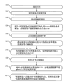
The method of the electric device starting that Fig. 4 diagram is implemented according to embodiments of the invention.To the various aspects of processor 301 be described for this figure.In step 402, activated current source in the time being activated corresponding to the passage of device under test.At first in step 403, the current regulating switch 330 of stopping using, thus prevent that electric current from during starts flowing through.
During this step 405, processor 301 is implemented detection of electrical leakage process 315.During detection of electrical leakage process 315, processor 301 uses module 306 monitoring departures electric currents.During normal circumstances, because switch 330 opens, so electric current detected from module 306.Electric current indication lead wire fault detected.If lead wire fault detected, processor 301 controls 313 transducers 304 and cuts out so, and operational failure reporting process 317 is reported leak current fault.
If electric leakage do not detected, in step 406, enable current regulating switch 330 so, and electric current starts to flow through load circuit.During step 407, processor 301 is carried out starting-impact control procedure 316.Impulsive control process 316 is carried out Limited Current rising by the levels of current control 318 providing to levels of current control driver 312 being increased to set rate.In one embodiment, every millisecond of fixed rate with about 1A/s of current setpoint increases, until its operating value that equals to have programmed.Impulsive control process 316 is used as LED and reaches heat balance some times are provided.Inner LED structure has the thermal time constant that several microseconds arrive several milliseconds conventionally.Starting-impact control 316 slowly increases electric currents at hundreds of millisecond, thereby provides the time for heat evenly diffuses through LED encapsulation, and may cause that lost efficacy and minimize mechanical stress temperature correlation.
During this step 407, the control current limit providing to overcurrent protection module 308 is also with similar speed oblique ascension.In certain embodiments, the threshold value between current limit and actual current level can during starts change.For example, can be by this Threshold for more approaching actual current level during starts.
During set up procedure 407 and normal running, processor 301 is carried out current imbalance and is detected 319.Processor 301 is monitored the departures electric current from module 306, and monitoring is from the inbound electric current of module 310.If electric current is unequal, electric current flows into load circuit from extraneous current source so, or flows out to extraneous dissipator from load circuit.Arbitrary circumstances is all indicated lead wire fault, and if this fault occurs, electric device is closed and reports fault so.Current sensing circuit (for example module 306 and 310) can operate in some error margin.These error margins can depend on electric current, voltage or both.In one embodiment, the form of the nominal error of processor 301 use between module 306 and 310 carrys out implementation process 319.If the current imbalance detecting is greater than at the normal possible error area of measuring between levels of current lower module 306 and 310, detect so and indication fault.
After operant level in the time that electric current is increased at completing steps 407, processor 301 starts adaptive voltage restriction 314 in step 408.In order to carry out adaptive voltage restriction 314, processor 301 is measured the voltage at current regulator 330 two ends, thereby measures the overvoltage at adjuster 330 places.Then by reducing maximum converter 313 voltage levvls, until overvoltage, in predetermined level, is controlled DC-DC transducer 313 with this.In one embodiment, overvoltage level is adjusted between 2-8V.
Then, processor 301 is waited for the time of scheduled volume, thereby allows load circuit stabilisation.In one embodiment, processor 301 is waited for approximately 5 minutes, so that stabilisation.
In the embodiment that adopts MOSFET as adjuster 330, after stabilisation, processor 301 performs step 410, thereby increases DC-DC transducer 304 voltages, to guarantee that MOSFET is operated in linear zone.In one embodiment, transducer 304 voltages are raised about 0.5V.
In step 411, by reduce DC-DC transducer 304 voltages with set rate, until the electric current sensing at low-pressure side electric current monitor 310 starts minimizing, the electric power that reduces to be utilized by current source with this.Once processor 301 detects slight minimizing, electric power reduces that step 411 completes and normal running starts.In one embodiment, this minimizing is the magnitude of several milliamperes.
In the normal operation period, processor continues to carry out adaptive voltage restriction 314.Adaptive voltage limit procedure 314 is controlled DC-DC transducer 304 available maximum output voltage is set in to the predetermined voltage level higher than the steady state voltage of load circuit.This has prevented that too much extra voltage is applied to load in the situation that of open circuit, and limits the impact of transient voltage spikes.Even if intermittently open fault occurs, because have little extra voltage at adjuster 330 places, only produce nominal current spike.
Fig. 5 diagram adaptive voltage limit procedure 314 in the normal operation period.The limit 502 illustrates that the source voltage that transducer 304 can not exceed complies with the limit.For example, source electrode limit can be 200V.Common transducer allows to comply with the limit and is less than the source that will be programmed in transducer and complies with the limit, and this limit is shown straight line 503.In order to illustrate, the limit of having programmed can be about 160V.Curve 505 illustrates actual load voltage V
f.As directed, the common pre-programmed limit 503 times, in actual load voltage be subject to exist between voltage limit larger surplus, thereby increase the potentiality of secondary failure infringement.Adaptive voltage limit procedure 314 times, the voltage of transducer 304 is limited to higher than V
fpredetermined voltage 504.After fault 506, circuit reaches new steady state voltage, and the limit reduces again.
Fig. 6 is the starting process of diagram embodiments of the invention and the sequential chart of normal running.In the drawings, curve 602 illustrates the V being exported by current source
highvoltage.Curve 603 illustrates the V that strides into station current sensing module 310 and adjuster 330 switch ends
lowvoltage.Curve 604 illustrates V
fload circuit voltage.Finally, curve 605 illustrates the electric current by load circuit.Normal starting and operating process comprise voltage ramp stage 615, electric current oblique ascension stage 616, surplus adjusting stage 617, stabilisation stage 618, electric power and reduce stage 619 and normal running 620.Beginning and the duration of various monitoring process 606-613 have been described for these operational phases below.
Before point 614 starts test process (and in whole test), operating temperature monitor procedure 609, thus detect the temperature outside operating parameter.In one embodiment, use by processor 301 the temperature sensor implementation process 609 that is coupled to electric device 300 or load circuit.Before test has just started, processor 301 activates power fails detection module 303 immediately, thus monitoring large-capacity power 610.Large-capacity power monitoring 610 continues in whole test.
Enable after 614 at passage, starting process starts from the voltage ramp stage 615.Be described in more detail this stage for the step 402-405 of Fig. 4 in the above.In the beginning in voltage ramp stage 615, transducer 304 is activated, and the maximum compliance voltage monitor procedure 614 of transducer is started.As discussed in the above, DC-DC transducer can have the maximum converter compliance voltage of built-in or pre-programmed.If exceed this voltage, transducer 304 is reported fault to processor 301 so.Earth Fault Detection process 612 also starts from the startup in voltage ramp stage 615.As described above, can by measure inbound and departures electric current carry out detection of ground faults.
After the voltage ramp stage 615, the electric current oblique ascension stage 616 starts.Be described in more detail this stage for the step 406 and 407 of Fig. 4 in the above.During the electric current oblique ascension stage 616, processor 301 is monitored the electric power being used by load circuit.If this electric power exceedes predetermined threshold value, processor 301 record troubles so.Finish in the electric current oblique ascension stage 616, processor starts voltage monitoring 606.If the voltage at load circuit two ends exceedes predetermined threshold value, voltage monitoring process 606 transmitted signal notice faults so.
The surplus adjusting stage 617 followed after the electric current oblique ascension stage 616, and had described for the step 408 of Fig. 4 in the above.After the surplus adjusting stage 617, processor carries out the stabilisation stage 618.In an illustrated embodiment, before normal running, this stage carries out approximately 5 minutes.During this stage, processor 301 starts dV/dt and detects 320, as described above.In certain embodiments, this activation occurs after the beginning in stabilisation stage 618.In one embodiment, dV/dT detection 611 started after 15 seconds.Describe electric power for the step 410 and 411 of Fig. 5 in the above and reduced the stage 619.After electric power reduces the stage 619, system starts normal running 620.
As used herein, term module can be described the functional given unit that can carry out according to one or more embodiment according to the present invention.As used herein, can utilize any form in hardware, software or its combination to implement module.In force, various modules described here may be embodied as separate module, or the function of describing and feature can be between one or more modules be partially or completely shared.In other words, as obvious for those skilled in the art after reading this specification, various feature described here and functional can enforcement in any given application, and can various combinations with displacement in one or more separate or sharing module in implement.Even if the element of various feature or functions can be described separately or require as separation module, those skilled in the art also will understand, these features and functional can sharing between one or more common software and hardware elements, and this description should not require or imply that the hardware of separation or software part are used to implement this category feature or functional.
In the situation that parts of the present invention or module are used implement software wholly or in part, in one embodiment, these software elements may be implemented as with functional calculating or the processing module operation that can carry out for its description.Figure 7 illustrates a this example calculations module.Various embodiment describe according to this example calculations module 700.After reading this description, how to use other computing module or framework to implement the present invention, will become for those skilled in the art obvious.
With reference now to Fig. 7,, computing module 700 can typical example as the calculating of finding in following equipment or disposal ability: desktop computer, laptop computer or notebook; Handheld computing device (PDA, smart phone, cell phone, palmtop PC etc.), large-scale computer, supercomputer, work station or server; Maybe can expect and be suitable for the special or general-purpose calculating appts of any other type of given application or environment.Computing module 700 also can represent be embedded in to locking equipment or otherwise can be used for the computing capability to locking equipment.For example, can in other electronic equipment, find computing module, for example digital camera, navigation system, cell phone, portable computing equipment, modulator-demodulator, router, WAP, terminal and can comprise other electronic equipment of the disposal ability of some forms.
In alternative embodiment, information storage mechanism 710 can comprise for allowing computer program or other instruction or data to be loaded into other similar installation of computing module 700.This class device can comprise for example fixing or removable memory cell 722 and interface 720.The example of this class memory cell 722 and interface 720 (for example can comprise program cassette tape and cassette tape interface, removable memory, flash memories or other removable memory module) and memory bank, PCMCIA slot and card, and allow that software and data are delivered to computing module 700 from memory cell 722 other fix or removable memory cell 722 and interface 720.

In this document, term " computer program medium " and " computer usable medium " are used for referring generally to the medium of generation such as memory 708, memory cell 710, medium 714 and passage 728.These and other various forms of computer program medium or computer usable medium can relate to the one or more sequences of one or more instructions are transported to treatment facility so as to carry out.This class instruction being included on medium is commonly referred to as " computer program code " or " computer program " (it can come in groups by the form of computer program or other grouping).In the time carrying out, this class instruction can make computing module 700 can carry out feature or function of the present invention as in this discussion.
Although described embodiments of the invention above, should be understood that they only as an example rather than restriction present.Equally, various figure can describe for exemplary architecture of the present invention or other configuration, and doing is like this can comprise feature in the present invention and functional in order to help to understand.Exemplary architecture shown in the invention is not restricted to or configuration, but can use multiple replaceable framework and configuration to implement the feature of wishing.Certainly, thereby the feature of wishing of the present invention is implemented in division and the configuration that can how to implement replaceable function, logic OR physics, and this will be obvious for those skilled in the art.Equally, the numerous different composition module names except describing at this can be applied to various divisions.In addition, describe and claim to a method about flow chart, operation, the order that step presents at this does not require that various embodiment are implemented as narrate with same sequence execution functional, unless context regulation.
Although described the present invention according to various exemplary embodiments and enforcement in the above, but should understand, the various features of the one or more middle descriptions in each embodiment, aspect and functionally on their applicability, be not limited to the specific embodiment that they are described, but instead, they can be separately or are applied to one or more in other embodiments of the invention with various compound modes, no matter whether described this class embodiment, and no matter whether this category feature is rendered as a part of having described embodiment.Therefore, should not limit range of the present invention and protection range by any one in above-described exemplary embodiment.
The term using in this document and phrase and various variant thereof, unless clearly statement, otherwise should be interpreted as open rather than restrictive.Example as the aforementioned: term " comprises/comprise " that should be read as the meaning is " comprise/comprise, not restriction " etc.; Term " example/example " is used to provide the illustrative examples of project in discussion, rather than exclusive or limit its list; It is " at least one ", " one or more " etc. that term " " or " one " should be read as the meaning; And adjective is " routine ", " traditional ", " normally ", " standard ", " known " for example, and the term of similar meaning should not be construed as described project is limited to the given period, or the project that can use in preset time, but instead, being understood to include can be now or in the technology of any time available or known conventional, traditional, normal or standard in future.Equally, mention the obvious or known technology of those skilled in the art in this document, this class technology comprise now or in future any time to the obvious or known technology of those skilled in the art.
In some instances, it is to be intended to or to require narrower situation in the example that can lack this class and widen phrase that for example existence of " one or more ", " at least ", " but being not limited to " or other similar phrase of the word and expression of widening should not be construed as the meaning.The use of term " module " not hint is described or requires parts or functional being all configured in common encapsulation for a part for module.Certainly, no matter any or all of in the various parts of module, be control logic or other parts, can be combined in single package or separated maintenance, and can further be distributed in multiple groupings or encapsulation or across multiple position distribution.
In addition, various embodiment set forth herein describes according to block diagram, flow chart and other diagram.As after reading this document, those skilled in the art become significantly, the embodiment shown in can implementing and various replacement thereof, and the example shown in being not limited to.For example, block diagram and follow to describe and should not be construed as and require certain architectures or configuration.
Claims (29)
1. an error protection current source, comprises:
Positive current output and negative current output, described positive current output and described negative current output are configured to provide operating current and operating voltage to load;
DC-DC transducer, described DC-DC transducer is configured to from processor reception control signal, and adjusts the output voltage of described current source in response to described control signal;
Overcurrent detection module, described overcurrent detection module is configured to monitoring flow crosses the electric current of described positive current output or negative current output, and described electric current and the control electric current of the levels of current control signal indication being provided by described processor are compared; And
Described processor, described processor is configured to monitor the voltage between described positive current output and described negative current output, thereby determine the steady state voltage at described load two ends, and provide described control signal to described DC-DC transducer, thereby described output voltage is set in to the predetermined voltage level higher than described steady state voltage, and described processor is further configured to provide described levels of current control signal to described overcurrent detection module.
2. current source according to claim 1, further comprise current cut-off, described current cut-off is configured to control the electric current of flowing through in described positive current output or described negative current output, and cuts off described electric current in response to the control signal receiving from described overcurrent detection module.
3. current source according to claim 2, further comprise the second current cut-off, another the electric current in described positive current output or described negative current output is flow through in described the second current cut-off control, and cuts off described electric current in response to the described control signal receiving from described overcurrent detection module.
4. current source according to claim 2, wherein said processor is configured to measure the rate of change of the voltage between described positive current output and described negative current output, thereby and provides the second control signal to cut off described electric current to described current cut-off.
5. current source according to claim 1, further comprises current rate limiter, and described current rate limiter is connected and is configured to described DC-DC transducer the variation of described electric current is limited to predetermined rate of change.
6. current source according to claim 1, further comprises current-limiting circuit, and described current-limiting circuit is connected with described negative current output and is configured to positive current is restricted to lower than predetermined positive current threshold value and prevents negative current.
7. current source according to claim 6, wherein said processor is configured to provide described predetermined positive current threshold value to described current-limiting circuit, and wherein said processor is further configured to, during start-up function, described predetermined positive current threshold value is increased to the second level from the first level.
8. current source according to claim 1, further comprise power fails detection module, described power fails detection module is coupled to described DC-DC transducer and is configured to the startup of sensing power fails, thereby and provides control signal to cut off described electric current to described DC-DC transducer.
9. current source according to claim 1, further comprises the communication interface that is coupled to described processor.
10. current source according to claim 9, wherein said processor is configured to detection failure and reports described fault via described communication interface.
11. current sources according to claim 9, wherein said communication interface is configured to detect dropped communication link, and if described dropped communication link detected, thereby transmits control signal and closes described electric current to described processor.
12. current sources according to claim 1, wherein said processor is configured to measure poor by between the electric current of described positive current output output and the electric current that enters by described negative current output, and if described difference exceedes predetermined value, fault detected.
13. current sources according to claim 1, wherein said processor is configured to carry out start-up function, and described start-up function comprises:
Forbid that electric current flows through described negative current output;
Transmit control signal to described DC-DC transducer, thereby increase described output voltage with the increase speed of being scheduled to, until described output voltage exceedes described operating voltage one scheduled volume; And
Make electric current can flow through described negative current output.
14. current sources according to claim 13, during wherein said start-up function is further included in the step transmitting control signal to described DC-DC transducer, the electric current of described positive current output is flow through in measurement, and if electric current flows through described positive current output, transmitted signal notice fault.
15. current sources according to claim 13, wherein said start-up function further comprises:
The maximum output current of described current source is increased to predetermined level with the speed of being scheduled to from 0A; And
Reduce described output voltage, reduce until flow through the electric current of described negative current output.
The method in 16. 1 kinds of operating current sources, comprises:
Provide operating current and operating voltage by positive current output and negative current output to load;
In response to the control signal being received from processor by DC-DC transducer, adjust the output voltage of described DC-DC transducer;
Overcurrent detection module monitoring flow is crossed the electric current of described positive current output or negative current output, and described electric current and the control electric current of the levels of current control signal indication being provided by described processor are compared;
Described processor is monitored the voltage between described positive current output and described negative current output, thereby determine the steady state voltage at described load two ends, and provide described control signal to described DC-DC transducer, thereby described output voltage is set in to the predetermined voltage level higher than described steady state voltage; And
Described processor provides described levels of current control signal to described overcurrent detection module.
17. methods according to claim 16, further comprise current cut-off control and flow through the electric current of in described positive current output or described negative current output, and described current cut-off cuts off described electric current in response to the control signal receiving from described overcurrent detection module.
18. methods according to claim 17, further comprise the second current cut-off control and flow through another the electric current in described positive current output or described negative current output; And described the second current cut-off cuts off described electric current in response to the described control signal receiving from described overcurrent detection module.
19. methods according to claim 17, further comprise described processor and measure the rate of change of the voltage between described positive current output and described negative current output, thereby and provide the second control signal to cut off described electric current to described current cut-off.
20. methods according to claim 16, further comprise the current rate limiter of connecting with described DC-DC transducer the variation of described electric current are limited to predetermined rate of change.
21. methods according to claim 16, further comprise the current-limiting circuit of connecting with described negative current output positive current are restricted to lower than predetermined positive current threshold value and prevent negative current.
22. methods according to claim 21, further comprising described processor provides described predetermined positive current threshold value to described current-limiting circuit, and described processor is increased to the second level by described predetermined positive current threshold value from the first level during start-up function.
23. methods according to claim 16, further comprise the startup of the power fails detection module sensing power fails that is coupled to described DC-DC transducer, thereby and provide control signal to cut off described electric current to described DC-DC transducer.
24. methods according to claim 16, further comprise described processor detection failure and report described fault via the communication interface that is coupled to described processor.
25. methods according to claim 24, further comprise described communication interface and detect dropped communication link, and if described dropped communication link detected, thereby transmit control signal and close described electric current to described processor.
26. methods according to claim 16, further comprise that described processor is measured the electric current by described positive current output output and the electric current that enters by described negative current output between poor, and if described difference exceedes predetermined value, fault detected.
27. methods according to claim 16, further comprise described processor and carry out start-up function, and described start-up function comprises:
Forbid that electric current flows through described negative current output;
Transmit control signal to described DC-DC transducer, thereby increase described output voltage with the increase speed of being scheduled to, until described output voltage exceedes described operating voltage one scheduled volume; And
Make electric current can flow through described negative current output.
28. methods according to claim 27, during wherein said start-up function is further included in the step transmitting control signal to described DC-DC transducer, the electric current of described positive current output is flow through in measurement, and if electric current flows through described positive current output, transmitted signal notice fault.
29. methods according to claim 27, wherein said start-up function further comprises:
The maximum output current of described current source is increased to predetermined level with the speed of being scheduled to from 0A; And
Reduce described output voltage, reduce until flow through the electric current of described negative current output.
Applications Claiming Priority (5)
| Application Number | Priority Date | Filing Date | Title |
|---|---|---|---|
| US28287010P | 2010-04-14 | 2010-04-14 | |
| US61/282,870 | 2010-04-14 | ||
| US13/086,313 US8503145B2 (en) | 2010-04-14 | 2011-04-13 | Fault protected current source for lighting element testing |
| US13/086,313 | 2011-04-13 | ||
| PCT/US2011/032528 WO2011130535A1 (en) | 2010-04-14 | 2011-04-14 | Fault protected current source for lighting element testing |
Publications (2)
| Publication Number | Publication Date |
|---|---|
| CN102948257A CN102948257A (en) | 2013-02-27 |
| CN102948257B true CN102948257B (en) | 2014-07-02 |
Family
ID=44787759
Family Applications (1)
| Application Number | Title | Priority Date | Filing Date |
|---|---|---|---|
| CN201180029223.5A Active CN102948257B (en) | 2010-04-14 | 2011-04-14 | Fault protected current source for lighting element testing |
Country Status (5)
| Country | Link |
|---|---|
| US (1) | US8503145B2 (en) |
| EP (1) | EP2559323B1 (en) |
| JP (1) | JP5889871B2 (en) |
| CN (1) | CN102948257B (en) |
| WO (1) | WO2011130535A1 (en) |
Families Citing this family (14)
| Publication number | Priority date | Publication date | Assignee | Title |
|---|---|---|---|---|
| EP2600694B1 (en) * | 2011-11-30 | 2013-11-20 | Vossloh-Schwabe Deutschland GmbH | LED driver circuit with constant power safe operating area |
| US9549440B2 (en) | 2012-05-29 | 2017-01-17 | Vektrex Electronic Systems, Inc. | Solid-state auxiliary lamp |
| EP2739119B1 (en) * | 2012-11-30 | 2015-08-19 | Dialog Semiconductor GmbH | Short circuit detection for lighting circuits |
| CN105325062B (en) | 2013-06-19 | 2017-11-10 | 戴乐格半导体公司 | LED driver with resultant fault protection |
| US10141739B1 (en) * | 2015-05-26 | 2018-11-27 | The Watt Stopper, Inc. | System for distributing DC power to and controlling building devices |
| US10093232B2 (en) | 2015-09-16 | 2018-10-09 | Truck-Lite Co., Llc | Telematics road ready system |
| US10065563B2 (en) * | 2015-09-16 | 2018-09-04 | Truck-Lite Co. Llc | Light emitting diode failure detection system for a vehicle |
| US10388161B2 (en) | 2015-09-16 | 2019-08-20 | Truck-Lite Co., Llc | Telematics road ready system with user interface |
| US20190268675A1 (en) | 2017-03-15 | 2019-08-29 | Scott Troutman | Telematics Road Ready System including a Bridge Integrator Unit |
| TWI720196B (en) * | 2017-05-10 | 2021-03-01 | 力智電子股份有限公司 | Dc-to-dc controller and control method thereof |
| CN109462910A (en) * | 2018-09-21 | 2019-03-12 | 上海亚明照明有限公司 | Monitoring system, method, storage medium and electric terminal suitable for LED lamp |
| CN112086945B (en) * | 2020-08-05 | 2022-04-01 | 广东美的白色家电技术创新中心有限公司 | Overvoltage protection circuit and electronic equipment |
| KR20220131063A (en) * | 2021-03-19 | 2022-09-27 | 에스케이하이닉스 주식회사 | Low-dropout regulator |
| KR102350618B1 (en) * | 2021-05-31 | 2022-01-13 | 유정구 | Integrated inspection device for LED module |
Citations (3)
| Publication number | Priority date | Publication date | Assignee | Title |
|---|---|---|---|---|
| CN101207953A (en) * | 2006-12-21 | 2008-06-25 | 钰瀚科技股份有限公司 | Light emitting diode driver as well as driving system |
| CN101271343A (en) * | 2007-03-19 | 2008-09-24 | 株式会社理光 | Power supply device, and LED device and electronic device using same |
| CN101505561A (en) * | 2008-02-05 | 2009-08-12 | 崇贸科技股份有限公司 | Control circuit for led drive and its off-line control circuit |
Family Cites Families (10)
| Publication number | Priority date | Publication date | Assignee | Title |
|---|---|---|---|---|
| JP4400880B2 (en) | 2004-10-05 | 2010-01-20 | 株式会社小糸製作所 | Lighting control circuit for vehicular lamp |
| JP4468316B2 (en) * | 2006-02-15 | 2010-05-26 | 株式会社日立製作所 | Overcurrent detection circuit and overcurrent detection method for power supply device |
| JP2007236126A (en) * | 2006-03-02 | 2007-09-13 | Sharp Corp | Power system and electronic apparatus employing the same |
| EP1916878B1 (en) * | 2006-10-27 | 2011-02-02 | Airbus Operations GmbH | Light monitoring system and method for operating same |
| US8405321B2 (en) | 2007-07-26 | 2013-03-26 | Rohm Co., Ltd. | Drive unit, smoothing circuit, DC/DC converter |
| US7756173B2 (en) * | 2008-06-20 | 2010-07-13 | Alfrey Anthony J | Laser diode driver with adaptive compliance voltage |
| JP2010074956A (en) * | 2008-09-18 | 2010-04-02 | Fuji Xerox Co Ltd | Power supply apparatus and image forming apparatus |
| US8035315B2 (en) * | 2008-12-22 | 2011-10-11 | Freescale Semiconductor, Inc. | LED driver with feedback calibration |
| US7986108B2 (en) * | 2009-05-08 | 2011-07-26 | Himax Analogic, Inc. | LED driver and start-up feedback circuit therein |
| JP2011035134A (en) * | 2009-07-31 | 2011-02-17 | Sanyo Electric Co Ltd | Light-emitting device driving circuit |
-
2011
- 2011-04-13 US US13/086,313 patent/US8503145B2/en active Active
- 2011-04-14 JP JP2013505145A patent/JP5889871B2/en active Active
- 2011-04-14 WO PCT/US2011/032528 patent/WO2011130535A1/en active Application Filing
- 2011-04-14 EP EP11717105.8A patent/EP2559323B1/en active Active
- 2011-04-14 CN CN201180029223.5A patent/CN102948257B/en active Active
Patent Citations (3)
| Publication number | Priority date | Publication date | Assignee | Title |
|---|---|---|---|---|
| CN101207953A (en) * | 2006-12-21 | 2008-06-25 | 钰瀚科技股份有限公司 | Light emitting diode driver as well as driving system |
| CN101271343A (en) * | 2007-03-19 | 2008-09-24 | 株式会社理光 | Power supply device, and LED device and electronic device using same |
| CN101505561A (en) * | 2008-02-05 | 2009-08-12 | 崇贸科技股份有限公司 | Control circuit for led drive and its off-line control circuit |
Non-Patent Citations (2)
| Title |
|---|
| Nurnberg, Germany.Series SSP120,SSP240,SSP320 Programmable Power Supplies.《SSP-KONSTANTER 32N Series SSP120,SSP240,SSP320 Programmable Power Supplies》.2005,P1-92. |
| Nurnberg, Germany.Series SSP120,SSP240,SSP320 Programmable Power Supplies.《SSP-KONSTANTER 32N Series SSP120,SSP240,SSP320 Programmable Power Supplies》.2005,P1-92. * |
Also Published As
| Publication number | Publication date |
|---|---|
| US20110254530A1 (en) | 2011-10-20 |
| US8503145B2 (en) | 2013-08-06 |
| EP2559323A1 (en) | 2013-02-20 |
| CN102948257A (en) | 2013-02-27 |
| EP2559323B1 (en) | 2018-05-23 |
| WO2011130535A1 (en) | 2011-10-20 |
| JP2013524768A (en) | 2013-06-17 |
| JP5889871B2 (en) | 2016-03-22 |
Similar Documents
| Publication | Publication Date | Title |
|---|---|---|
| CN102948257B (en) | Fault protected current source for lighting element testing | |
| US6541879B1 (en) | USB hub power management | |
| US10381838B2 (en) | Power control system with fault detection and data retention for energy generation systems | |
| CN107565600B (en) | Photovoltaic power optimizer, control method and device thereof and photovoltaic power generation system | |
| EP3734310A1 (en) | Power monitoring method, system and power supply | |
| US11721993B1 (en) | Battery management system | |
| KR20050026360A (en) | Battery protection circuit | |
| US20160109212A1 (en) | Electronic fuse | |
| CN109509508A (en) | Abnormal power failure test method, device, medium and equipment for SSD | |
| CN104052258A (en) | Fault Tolerant Power Supply Incorporating Intelligent Load Switch To Provide Uninterrupted Power | |
| US9368955B2 (en) | System and method to derive power and trip a circuit breaker from an external device | |
| WO2010087745A1 (en) | An electronic circuit breaker and a method of providing protection switching | |
| US8189313B1 (en) | Fault detection and handling for current sources | |
| JP2013070071A (en) | Method and system for powering integrated circuit, and integrated circuit used therein | |
| US8345398B2 (en) | Integrated variable output power supply protection circuit | |
| CN107870846A (en) | Fault element indicating means, equipment and system | |
| CN115808640A (en) | Power failure detection circuit, method, system, electronic device, and storage medium | |
| US6205039B1 (en) | Device for supervising a high voltage converter station | |
| US11506741B2 (en) | Method and apparatus for monitoring secondary power device, and electronic system including the apparatus | |
| US7477502B1 (en) | Method and system for providing fault protection in a power supply system | |
| CN105137369A (en) | LED string lamp operation state monitoring method and system | |
| CN115152326A (en) | Voltage sensing circuit and method | |
| EP3629039A1 (en) | Solid state power switch device | |
| US20240157835A1 (en) | A system and a method for in-situ controlling and monitoring individual battery cells in a battery system | |
| US20230118432A1 (en) | Discharge current limit loop for short circuit protection in reverse operation for buck-boost battery chargers |
Legal Events
| Date | Code | Title | Description |
|---|---|---|---|
| C06 | Publication | ||
| PB01 | Publication | ||
| C10 | Entry into substantive examination | ||
| SE01 | Entry into force of request for substantive examination | ||
| C14 | Grant of patent or utility model | ||
| GR01 | Patent grant |