CN102913157A - Underground sleeve rotational flow guider - Google Patents
Underground sleeve rotational flow guider Download PDFInfo
- Publication number
- CN102913157A CN102913157A CN201210443829XA CN201210443829A CN102913157A CN 102913157 A CN102913157 A CN 102913157A CN 201210443829X A CN201210443829X A CN 201210443829XA CN 201210443829 A CN201210443829 A CN 201210443829A CN 102913157 A CN102913157 A CN 102913157A
- Authority
- CN
- China
- Prior art keywords
- guiding
- water conservancy
- conservancy diversion
- hole
- rock debris
- Prior art date
- Legal status (The legal status is an assumption and is not a legal conclusion. Google has not performed a legal analysis and makes no representation as to the accuracy of the status listed.)
- Granted
Links
Images


Landscapes
- Earth Drilling (AREA)
Abstract
The invention discloses an underground sleeve rotational flow guider, which solves the problem that during the down sleeve operation, the sleeve cannot be lowered to the estimate position as the drilling fluid is poor in rock debris carrying capability. Guiding stators are arranged in an outer cylinder of the guider; inclined guiding round holes are arranged in the guiding stators; blade grids are fixed with the lower parts of the guiding stators through mandrels; and impellers are fixed with the tail ends of the mandrels. According to the invention, fluid axially flows in and impacts the blade grids to rotate after the running direction is changed by the inclined holes of the guiding stators, so as to provide power for the impellers at the lower parts of the mandrels and drive the impeller to rotate; the guider can be automatically driven underground, pushes away rock debris deposited at the well bottom, and enables the rock debris to go upwards easily, thereby improving the capability of carrying rock debris of drilling fluid, can grind and smash the rock debris at the well bottom, enables the rock debris to be impacted and carried away by water easily, and avoids the pipe-sticking danger as large particles are difficult to carry.
Description
Technical field
The present invention relates to the eddy flow cementing technology in sand washing, washing technology and the hydraulics in the petroleum works casing job.
Background technology
In the petroleum works casing job process, the effect of float shoe mainly be for the guide sleeves tubing string along the smooth G.I.H of pit shaft, prevent that sleeve bottom from inserting borehole wall rock stratum, reduce lower well resistance, also have simultaneously the ability of certain cutting carring.But the part well is because borehole well instability, cause cave-in or undergauge, because of the ability of Transport of Drilling Cutting In A inadequate, cause sand bridge or shaft bottom sand setting, because pit shaft exists sand bridge or shaft bottom sand setting, in case be hampered, the ability of float shoe flushing itself and cutting carring is inadequate, causes sleeve pipe can't descend estimating position.For this problem, Inst. of Engineering Technology, Liaohe Petroleum Exploration Bureau has designed well drilling detritus bed agitator, and its patent No. is 01271736.3, the advantage of this device is simple in structure, easy to use, only need be connected between the drilling rod and just landwaste in the drilling fluid can be discharged ground smoothly; But also have following shortcoming: the power of (1) Cutting Disposal mainly is stirring, the rolling action that utilizes helical blade, and active force is not very large, and the landwaste elimination efficiency is not high.(2) distance affects of helical blade and the borehole wall solids-carrying capacity, make original just very narrow annular space less, the space of having reduced the landwaste Upward Migration, the landwaste carrying capacity is not high.(3) multiplex in inclined shaft, little for hole cleaning, the cleaning action of straight well.(4) clean helpless especially for the well of the well section of caving in or easily collapse.Also have plenty of, a kind of drill bit pup joint that produces the hydraulic booster pulsation in the shaft bottom has been studied by Shengli Petroleum Administration Bureau Drilling Technology Academy, SINOPEC, and its patent No. is 03269456.3; The advantage of this device is to form in the shaft bottom periodic supercharging pulsation and negative pressure pulsation, thereby reduces " chip hold down effect " of landwaste, strengthens the bottom hole flushing effect, the efficient that the broken rock of raising jet, auxiliary rock creep into; But there is following shortcoming in it: (1) complex structure, in the process that produces pulse, can lose a lot of energy, and reduced the impact force of water jet.(2) must rely on supercharging and negative pressure pulsation to hocket to reduce " chip hold down effect ", have simultaneously intermittence, can not continuous operation or direct effect landwaste surface, purification efficiency is not high.
So it is very difficult that routine techniques is processed this problem, must pull out sleeve pipe when serious, the lower well that drills through is processed, and has wasted a large amount of man power and materials, and causes tremendous economic loss.
Summary of the invention
The objective of the invention is for the problem that exists in the background technology, a kind of down-hole casing Wind guiding device that replaces float shoe is provided, this guider can obviously improve the ability of Transport of Drilling Cutting In A, guarantees that sleeve pipe is lowered to the design well depth smoothly.
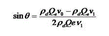
For achieving the above object, the technical scheme that the application adopts is: the down-hole casing Wind guiding device, comprise box cupling, urceolus, guiding stator, axle, leaf grating, impeller and guide holder, described box cupling and urceolus are cylindric, the two is threaded, the lower end of the urceolus guide holder that is threaded, guide holder is the hollow hemisphere shape; Fix three guiding stators by jackscrew successively from top to bottom in the above-mentioned urceolus; The main body of described guiding stator is discoid, and central shaft hole is set, and centered by central shaft hole, uniform six the water conservancy diversion inclination circular holes of hoop, the angle of inclination of water conservancy diversion inclination circular hole wherein adopts following formula to calculate:

In the formula:
v 0 Be the absolute flow velocity in water conservancy diversion inclination circular hole entrance, m/s;
v 1 Be the absolute flow velocity in water conservancy diversion inclination circular hole exit, m/s, can think in size with
v 0 Equate;
ρ d Be fluid density, kg/m
3 Q e Be the effective discharge by single water conservancy diversion inclination circular hole, L/s;
Three bearings of assembling on the described axle, these three bearings are mounted with respectively in the central shaft hole of guiding stator, assemble leaf grating on the axle between the adjacent two guiding stators; The lower end of the axle impeller that is threaded, the front end of impeller leans out the round surface of guide holder.
The entrance angle of preferred described leaf grating is that 63 ° ~ 66 °, exit angle are 36 ° ~ 40 °.
The entrance angle of preferred described leaf grating is that 64.5 °, exit angle are 38.3 °.
Down-hole casing Wind guiding device operating principle of the present invention
Flow axis is impacted leaf grating after changing flow direction by guiding stator angling hole when flowing into the down-hole casing Wind guiding device, and making the potential energy of fluid and kinetic transformation is mechanical energy, promotes leaf grating and rotates, for the impeller of axle bottom provides power, the impeller rotation; Wheel rotation has formed eddy flow field, can push the landwaste that is deposited on the shaft bottom open, overcomes head of liquid to " chip hold down effect " of shaft bottom landwaste, prevents that landwaste from shaft bottom accumulation and compacting, making landwaste be easy to return, thereby improves the ability of Transport of Drilling Cutting In A; Wheel rotation, when touching the larger landwaste of particle diameter, drill bit produces shear action to landwaste under the rotation torque effect, under twisting force, landwaste produces the crack along surface of shear, gradually broken, disintegrate, the landwaste particle diameter diminishes, and makes it easily by hydraulic blow, carries, avoid carrying the danger that bit freezing appears in difficulty because of bulky grain, and after being gone out the shaft bottom by water jet, can pass through smoothly annular space, return to ground.
Beneficial effect of the present invention: down-hole casing Wind guiding device of the present invention, can produce eddy flow, thereby in the process of advancing, push the landwaste that is deposited on the shaft bottom open, overcome head of liquid to " chip hold down effect " of shaft bottom landwaste, prevent that landwaste is in shaft bottom accumulation and compacting, make landwaste be easy to return, thereby improve the ability of Transport of Drilling Cutting In A; In addition, also can grind, pulverize the shaft bottom landwaste, destroy the bulk landwaste, make it easily by hydraulic blow, carry, avoid carrying because of bulky grain the danger of difficult bit freezing; This guider can drive voluntarily in the down-hole, realizes underground work, facts have proved, compares the conventional tool float shoe, and when processing the flushing work of equivalent landwaste, the used time of the present invention is shorter, and efficient is higher.
Description of drawings
Fig. 1 is the structural representation of Wind guiding device of the present invention.
Fig. 2 is the structural representation of guiding stator.
Fig. 3 is the A-A view among Fig. 2.
The specific embodiment
Below in conjunction with accompanying drawing and specific embodiment, the present invention is further illustrated for the experiment Comparative Examples:
Embodiment 1
The down-hole casing Wind guiding device, comprise box cupling 1, urceolus 2, guiding stator 6, axle 4, leaf grating 7, impeller 8 and guide holder 9, described box cupling 1 and urceolus 2 are cylindric, the two is threaded, the lower end of urceolus 2 guide holder 9 that is threaded, this guide holder 9 is similar with the structure of float shoe, for hollow hemispherical, utilizes successively from top to bottom jackscrew 3 to fix three guiding stators 6 in the urceolus 2; By shown in Figure 2: the main body of described guiding stator 6 is discoid, and central shaft hole is set, and centered by central shaft hole, uniform six the water conservancy diversion inclination circular holes of hoop, wherein water conservancy diversion inclination circular hole the angle of inclination adopt following formula to calculate:
In the formula:
v 0 Be the absolute flow velocity in water conservancy diversion inclination circular hole entrance, m/s;
v 1 Be the absolute flow velocity in water conservancy diversion inclination circular hole exit, m/s, can think in size with
v 0 Equate;
ρ d Be fluid density, kg/m
3 Q e Be the effective discharge by single water conservancy diversion inclination circular hole, L/s; When the applicant was Φ 30 according to the diameter of the water conservancy diversion inclination circular hole of above-mentioned formula design, the angle of inclination of water conservancy diversion inclination circular hole was 45 °; Three bearings 5 of assembling on the described axle 4, these three bearings 5 are mounted with respectively in the central shaft hole of guiding stator 6, assembling leaf grating 7 on the axle 4 between the adjacent two guiding stators 6; Described leaf grating entrance angle is 63 °~66 °, and being preferably 64.5 °, exit angle is 36 °~40 °, is preferably 38.3 °; The lower end of axle 4 impeller 8 that is threaded, the front end of impeller 8 leans out the round surface of guide holder 9.
Experiment Comparative Examples one: solids-carrying capacity contrast
Experimental technique: a certain proportion of large and small landwaste level is placed the pit shaft bottom, in pit shaft, stack certain altitude, and keep the interior landwaste amount of each experiment well constant.Experimental Flowing Object is conventional drilling fluid, keeps pump pressure constant;
(1) put into conventional float shoe in simulation wellbore hole the shaft bottom landwaste is washed, started device 10 minutes, last landwaste weight and particle diameter distribute at the bottom of the measuring well;
(2) replace float shoe with Wind guiding device of the present invention, repeat aforesaid operations.
Above-mentioned solids-carrying capacity comparing result such as following table:
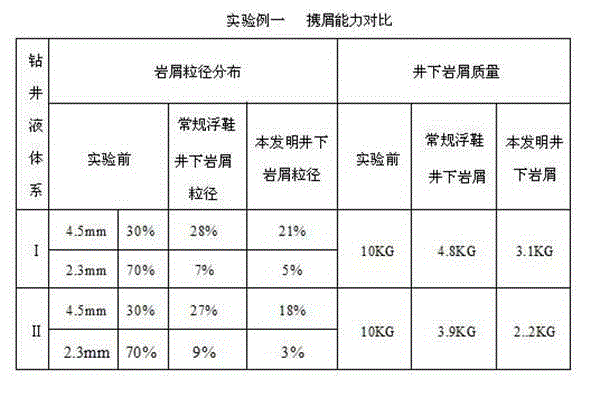
Experimental example one shows that under the same case, Wind guiding device of the present invention is larger than the silt carrying capacity of conventional float shoe.Distribute as can be known by the particle diameter of measuring and contrast the residue landwaste, two kinds of instruments all can carry out well with most of small particle diameter landwaste, total amount is many but the present invention takes bits, the large landwaste amount of the residue percentage of instrument of the present invention reduces simultaneously, the present invention is described in the process that landwaste is washed, carries, also has grinding, fragmentation to large particle diameter landwaste concurrently.
Experiment Comparative Examples two: take the contrast of bits efficient
Experimental technique: the uniform landwaste level of particle diameter is placed the pit shaft bottom, in pit shaft, stack certain altitude, keep the interior landwaste amount of each experiment well constant.Experimental Flowing Object is conventional drilling fluid, keeps pump pressure constant;
(1) under normal pressure and 15MPa pressure condition, in simulation wellbore hole, utilizes conventional float shoe that the shaft bottom landwaste is washed respectively, start device until landwaste is thoroughly removed, write down required time;
(2) replace float shoe with Wind guiding device of the present invention, repeat aforesaid operations.
The above-mentioned bits efficient comparing result of taking sees the following form:
Experimental example two shows that under the general case, when processing the landwaste of same amount, the used time of the present invention will obviously be less than conventional tool, and it is relatively high to take bits efficient.Under larger head of liquid, " chip hold down effect " prolonged the engineering time of traditional sand flushing tool, and the present invention institute is influenced less, and it is little to take the variation of bits time, illustrates that the present invention can effectively overcome " chip hold down effect ", guarantees to take bits efficient.
Claims (3)
1. down-hole casing Wind guiding device, comprise box cupling, urceolus, guiding stator, axle, leaf grating, impeller and guide holder, it is characterized in that: described box cupling and urceolus are cylindric, and the two is threaded, the lower end of the urceolus guide holder that is threaded, guide holder is the hollow hemisphere shape; In the urceolus from top to bottom successively jackscrew fix three the guiding stators; The main body of described guiding stator is discoid, and central shaft hole is set, and centered by central shaft hole, uniform six the water conservancy diversion inclination circular holes of hoop, the incline direction of above-mentioned water conservancy diversion inclination circular hole is consistent, and the angle of inclination of water conservancy diversion inclination circular hole adopts following formula to calculate:

In the formula:
v 0 Be the absolute flow velocity in water conservancy diversion inclination circular hole entrance, m/s;
v 1 Be the absolute flow velocity in water conservancy diversion inclination circular hole exit, m/s, can think in size with
v 0 Equate;
ρ d Be fluid density, kg/m
3 Q e Be the effective discharge by single water conservancy diversion inclination circular hole, L/s;
Three bearings of assembling on the described axle, these three bearings are mounted with respectively in the central shaft hole of guiding stator, assemble leaf grating on the axle between the adjacent two guiding stators; The lower end of the axle impeller that is threaded, the front end of impeller leans out the guide holder round surface.
2. down-hole casing Wind guiding device according to claim 1 is characterized in that: the entrance angle of described leaf grating is that 63 °~66 °, exit angle are 36 °~40 °.
3. down-hole casing Wind guiding device according to claim 2 is characterized in that: the entrance angle of described leaf grating is that 64.5 °, exit angle are 38.3 °.
Priority Applications (1)
| Application Number | Priority Date | Filing Date | Title |
|---|---|---|---|
| CN201210443829.XA CN102913157B (en) | 2012-11-08 | 2012-11-08 | Underground sleeve rotational flow guider |
Applications Claiming Priority (1)
| Application Number | Priority Date | Filing Date | Title |
|---|---|---|---|
| CN201210443829.XA CN102913157B (en) | 2012-11-08 | 2012-11-08 | Underground sleeve rotational flow guider |
Publications (2)
| Publication Number | Publication Date |
|---|---|
| CN102913157A true CN102913157A (en) | 2013-02-06 |
| CN102913157B CN102913157B (en) | 2015-04-22 |
Family
ID=47611700
Family Applications (1)
| Application Number | Title | Priority Date | Filing Date |
|---|---|---|---|
| CN201210443829.XA Active CN102913157B (en) | 2012-11-08 | 2012-11-08 | Underground sleeve rotational flow guider |
Country Status (1)
| Country | Link |
|---|---|
| CN (1) | CN102913157B (en) |
Cited By (9)
| Publication number | Priority date | Publication date | Assignee | Title |
|---|---|---|---|---|
| CN103352663A (en) * | 2013-07-31 | 2013-10-16 | 西南石油大学 | Drilling centralizer capable of removing rocks and debris beds at bottom of well |
| CN104234650A (en) * | 2014-09-04 | 2014-12-24 | 中国石油天然气集团公司 | Casing lowering tool and method |
| CN104790872A (en) * | 2015-03-24 | 2015-07-22 | 王殿义 | Self-exciting guiding device with drilling function |
| CN106639930A (en) * | 2016-12-22 | 2017-05-10 | 扬州大泽石油工程技术有限公司 | Vortex generator |
| CN106761472A (en) * | 2016-12-29 | 2017-05-31 | 德州汉隆石油设备有限公司 | Self- steering covers tube vibration guide shoe |
| CN107401378A (en) * | 2017-09-20 | 2017-11-28 | 中国石油大学(北京) | Drill bit |
| CN108266130A (en) * | 2017-12-27 | 2018-07-10 | 中国石油集团长城钻探工程有限公司 | Assist steerable drilling drilling rod and rotary steerable drilling device |
| CN111749632A (en) * | 2020-07-09 | 2020-10-09 | 合力(天津)能源科技股份有限公司 | High-pressure rotating cleaning drilling and grinding device |
| CN115387751A (en) * | 2022-08-29 | 2022-11-25 | 西南石油大学 | Underground reverse rotational flow opposite-flushing cavitation device |
Citations (7)
| Publication number | Priority date | Publication date | Assignee | Title |
|---|---|---|---|---|
| SU615200A1 (en) * | 1970-12-07 | 1978-07-15 | Уфимский Нефтяной Институт | Device for hydrodynamic investigation of wells |
| CN2642983Y (en) * | 2003-08-14 | 2004-09-22 | 中国石化集团胜利石油管理局钻井工艺研究院 | Bit sub capable of generating waterpower supercharging pulse at well bottom |
| CN1727833A (en) * | 2004-07-30 | 2006-02-01 | 株洲工学院 | Bringing along automatic cleanout inside pipe by teeth at rotational flow mouth, and technique for strengthening heat transfer |
| CN201407022Y (en) * | 2009-04-13 | 2010-02-17 | 中国海洋石油总公司 | Hydraulic drive type mixer for polymer injection |
| US7980329B2 (en) * | 2006-03-06 | 2011-07-19 | Exxonmobil Upstream Research Company | System for managing variable density drilling mud |
| CN202031534U (en) * | 2011-05-16 | 2011-11-09 | 王震 | Downhole rotational-flow shearing generator |
| CN102434115A (en) * | 2011-11-28 | 2012-05-02 | 西南石油大学 | Strong rotational flow sleeve centralizer |
-
2012
- 2012-11-08 CN CN201210443829.XA patent/CN102913157B/en active Active
Patent Citations (7)
| Publication number | Priority date | Publication date | Assignee | Title |
|---|---|---|---|---|
| SU615200A1 (en) * | 1970-12-07 | 1978-07-15 | Уфимский Нефтяной Институт | Device for hydrodynamic investigation of wells |
| CN2642983Y (en) * | 2003-08-14 | 2004-09-22 | 中国石化集团胜利石油管理局钻井工艺研究院 | Bit sub capable of generating waterpower supercharging pulse at well bottom |
| CN1727833A (en) * | 2004-07-30 | 2006-02-01 | 株洲工学院 | Bringing along automatic cleanout inside pipe by teeth at rotational flow mouth, and technique for strengthening heat transfer |
| US7980329B2 (en) * | 2006-03-06 | 2011-07-19 | Exxonmobil Upstream Research Company | System for managing variable density drilling mud |
| CN201407022Y (en) * | 2009-04-13 | 2010-02-17 | 中国海洋石油总公司 | Hydraulic drive type mixer for polymer injection |
| CN202031534U (en) * | 2011-05-16 | 2011-11-09 | 王震 | Downhole rotational-flow shearing generator |
| CN102434115A (en) * | 2011-11-28 | 2012-05-02 | 西南石油大学 | Strong rotational flow sleeve centralizer |
Cited By (14)
| Publication number | Priority date | Publication date | Assignee | Title |
|---|---|---|---|---|
| CN103352663B (en) * | 2013-07-31 | 2016-06-29 | 西南石油大学 | Can the well drilling centralizer of the clear rock in shaft bottom and Cutting Disposal |
| CN103352663A (en) * | 2013-07-31 | 2013-10-16 | 西南石油大学 | Drilling centralizer capable of removing rocks and debris beds at bottom of well |
| CN104234650A (en) * | 2014-09-04 | 2014-12-24 | 中国石油天然气集团公司 | Casing lowering tool and method |
| CN104790872A (en) * | 2015-03-24 | 2015-07-22 | 王殿义 | Self-exciting guiding device with drilling function |
| CN104790872B (en) * | 2015-03-24 | 2016-07-06 | 王殿义 | Auto-excitation type guider can be bored |
| CN106639930B (en) * | 2016-12-22 | 2022-11-15 | 中国石油大学(北京) | Vortex generator |
| CN106639930A (en) * | 2016-12-22 | 2017-05-10 | 扬州大泽石油工程技术有限公司 | Vortex generator |
| CN106761472A (en) * | 2016-12-29 | 2017-05-31 | 德州汉隆石油设备有限公司 | Self- steering covers tube vibration guide shoe |
| CN107401378A (en) * | 2017-09-20 | 2017-11-28 | 中国石油大学(北京) | Drill bit |
| CN107401378B (en) * | 2017-09-20 | 2023-10-27 | 中国石油大学(北京) | Drill bit |
| CN108266130A (en) * | 2017-12-27 | 2018-07-10 | 中国石油集团长城钻探工程有限公司 | Assist steerable drilling drilling rod and rotary steerable drilling device |
| CN111749632A (en) * | 2020-07-09 | 2020-10-09 | 合力(天津)能源科技股份有限公司 | High-pressure rotating cleaning drilling and grinding device |
| CN115387751A (en) * | 2022-08-29 | 2022-11-25 | 西南石油大学 | Underground reverse rotational flow opposite-flushing cavitation device |
| CN115387751B (en) * | 2022-08-29 | 2023-06-09 | 西南石油大学 | Downhole reverse rotational flow opposite-impact cavitation device |
Also Published As
| Publication number | Publication date |
|---|---|
| CN102913157B (en) | 2015-04-22 |
Similar Documents
| Publication | Publication Date | Title |
|---|---|---|
| CN102913157B (en) | Underground sleeve rotational flow guider | |
| CN104832083B (en) | Helicoid hydraulic motor and its rock-breaking and well-drilling method | |
| CN101275458B (en) | Reverse circulation construction technique and apparatus of single rope impact drill | |
| CN104763343B (en) | A kind of multistage borehole-enlarging drilling tool and its expanding method of the bionical nozzle of build-in | |
| EP1787007A2 (en) | Impact excavation system and method | |
| WO2008055349A1 (en) | Reverse nozzle drill bit | |
| CN208183839U (en) | A kind of strand suction suction dredge | |
| CN103967439A (en) | Continuous milling and salvage integrated tool and milling and salvage method thereof | |
| CN102691477A (en) | Rock debris cleaning device for drilling tool | |
| CN101899956B (en) | Method for salvaging electric pump pipe column fish | |
| CN105041246B (en) | A kind of reverse circulation down-hole hammer transformational structure | |
| CN106677733A (en) | Large-diameter drilling drill with drill residue salvaging device | |
| CN209067141U (en) | Turbine mill shoe of dredging pipe scale removal | |
| Cao et al. | Investigation on the cuttings carrying capacity of a novel retractable drill bit used in casing while drilling with air reverse circulation | |
| CN102425370B (en) | Hole bottom oil pressure motor lithoclast combined power drilling tool construction method and device | |
| CN1576511A (en) | Method for drilling a borehole and wet boring tool | |
| CN206071508U (en) | A kind of waterpower screw rod self-loopa sand-bailing equipment | |
| CN102767337A (en) | Sleeve type screw pile machine drill and construction method for eliminating barriers | |
| WO1983000183A1 (en) | Hydraulic down-the-hole rock drill | |
| WO2015026905A1 (en) | Percussion hammer bit | |
| CN202073498U (en) | Chambering type pressure-reduction acceleration drill bit | |
| CN214886901U (en) | Short joint for removing rock debris during tripping and drill string assembly | |
| CN205908266U (en) | Whirl sand removal ware | |
| CN201544128U (en) | Hydraulic sand-blasting cutter | |
| TWM553756U (en) | Rotary and impulsive well-drilling rig |
Legal Events
| Date | Code | Title | Description |
|---|---|---|---|
| C06 | Publication | ||
| PB01 | Publication | ||
| C10 | Entry into substantive examination | ||
| SE01 | Entry into force of request for substantive examination | ||
| C14 | Grant of patent or utility model | ||
| GR01 | Patent grant |