CN1029038C - Optical fiber connector buildout system - Google Patents
Optical fiber connector buildout system Download PDFInfo
- Publication number
- CN1029038C CN1029038C CN91109669A CN91109669A CN1029038C CN 1029038 C CN1029038 C CN 1029038C CN 91109669 A CN91109669 A CN 91109669A CN 91109669 A CN91109669 A CN 91109669A CN 1029038 C CN1029038 C CN 1029038C
- Authority
- CN
- China
- Prior art keywords
- plug
- assembly
- extra block
- tube
- adapter
- Prior art date
- Legal status (The legal status is an assumption and is not a legal conclusion. Google has not performed a legal analysis and makes no representation as to the accuracy of the status listed.)
- Expired - Fee Related
Links
Images


Classifications
-
- G—PHYSICS
- G02—OPTICS
- G02B—OPTICAL ELEMENTS, SYSTEMS OR APPARATUS
- G02B6/00—Light guides; Structural details of arrangements comprising light guides and other optical elements, e.g. couplings
- G02B6/24—Coupling light guides
- G02B6/36—Mechanical coupling means
- G02B6/40—Mechanical coupling means having fibre bundle mating means
-
- G—PHYSICS
- G02—OPTICS
- G02B—OPTICAL ELEMENTS, SYSTEMS OR APPARATUS
- G02B6/00—Light guides; Structural details of arrangements comprising light guides and other optical elements, e.g. couplings
- G02B6/24—Coupling light guides
- G02B6/36—Mechanical coupling means
- G02B6/38—Mechanical coupling means having fibre to fibre mating means
- G02B6/3807—Dismountable connectors, i.e. comprising plugs
- G02B6/3897—Connectors fixed to housings, casing, frames or circuit boards
-
- G—PHYSICS
- G02—OPTICS
- G02B—OPTICAL ELEMENTS, SYSTEMS OR APPARATUS
- G02B6/00—Light guides; Structural details of arrangements comprising light guides and other optical elements, e.g. couplings
- G02B6/24—Coupling light guides
- G02B6/26—Optical coupling means
- G02B6/264—Optical coupling means with optical elements between opposed fibre ends which perform a function other than beam splitting
-
- G—PHYSICS
- G02—OPTICS
- G02B—OPTICAL ELEMENTS, SYSTEMS OR APPARATUS
- G02B6/00—Light guides; Structural details of arrangements comprising light guides and other optical elements, e.g. couplings
- G02B6/24—Coupling light guides
- G02B6/36—Mechanical coupling means
- G02B6/38—Mechanical coupling means having fibre to fibre mating means
- G02B6/3807—Dismountable connectors, i.e. comprising plugs
- G02B6/381—Dismountable connectors, i.e. comprising plugs of the ferrule type, e.g. fibre ends embedded in ferrules, connecting a pair of fibres
- G02B6/3818—Dismountable connectors, i.e. comprising plugs of the ferrule type, e.g. fibre ends embedded in ferrules, connecting a pair of fibres of a low-reflection-loss type
- G02B6/3821—Dismountable connectors, i.e. comprising plugs of the ferrule type, e.g. fibre ends embedded in ferrules, connecting a pair of fibres of a low-reflection-loss type with axial spring biasing or loading means
-
- G—PHYSICS
- G02—OPTICS
- G02B—OPTICAL ELEMENTS, SYSTEMS OR APPARATUS
- G02B6/00—Light guides; Structural details of arrangements comprising light guides and other optical elements, e.g. couplings
- G02B6/24—Coupling light guides
- G02B6/36—Mechanical coupling means
- G02B6/38—Mechanical coupling means having fibre to fibre mating means
- G02B6/3807—Dismountable connectors, i.e. comprising plugs
- G02B6/381—Dismountable connectors, i.e. comprising plugs of the ferrule type, e.g. fibre ends embedded in ferrules, connecting a pair of fibres
- G02B6/3826—Dismountable connectors, i.e. comprising plugs of the ferrule type, e.g. fibre ends embedded in ferrules, connecting a pair of fibres characterised by form or shape
- G02B6/3831—Dismountable connectors, i.e. comprising plugs of the ferrule type, e.g. fibre ends embedded in ferrules, connecting a pair of fibres characterised by form or shape comprising a keying element on the plug or adapter, e.g. to forbid wrong connection
-
- G—PHYSICS
- G02—OPTICS
- G02B—OPTICAL ELEMENTS, SYSTEMS OR APPARATUS
- G02B6/00—Light guides; Structural details of arrangements comprising light guides and other optical elements, e.g. couplings
- G02B6/24—Coupling light guides
- G02B6/36—Mechanical coupling means
- G02B6/38—Mechanical coupling means having fibre to fibre mating means
- G02B6/3807—Dismountable connectors, i.e. comprising plugs
- G02B6/3873—Connectors using guide surfaces for aligning ferrule ends, e.g. tubes, sleeves, V-grooves, rods, pins, balls
- G02B6/3874—Connectors using guide surfaces for aligning ferrule ends, e.g. tubes, sleeves, V-grooves, rods, pins, balls using tubes, sleeves to align ferrules
- G02B6/3877—Split sleeves
-
- G—PHYSICS
- G02—OPTICS
- G02B—OPTICAL ELEMENTS, SYSTEMS OR APPARATUS
- G02B6/00—Light guides; Structural details of arrangements comprising light guides and other optical elements, e.g. couplings
- G02B6/24—Coupling light guides
- G02B6/36—Mechanical coupling means
- G02B6/38—Mechanical coupling means having fibre to fibre mating means
- G02B6/3807—Dismountable connectors, i.e. comprising plugs
- G02B6/389—Dismountable connectors, i.e. comprising plugs characterised by the method of fastening connecting plugs and sockets, e.g. screw- or nut-lock, snap-in, bayonet type
- G02B6/3891—Bayonet type
-
- G—PHYSICS
- G02—OPTICS
- G02B—OPTICAL ELEMENTS, SYSTEMS OR APPARATUS
- G02B6/00—Light guides; Structural details of arrangements comprising light guides and other optical elements, e.g. couplings
- G02B6/24—Coupling light guides
- G02B6/36—Mechanical coupling means
- G02B6/38—Mechanical coupling means having fibre to fibre mating means
- G02B6/3807—Dismountable connectors, i.e. comprising plugs
- G02B6/3833—Details of mounting fibres in ferrules; Assembly methods; Manufacture
- G02B6/3854—Ferrules characterised by materials
Landscapes
- Physics & Mathematics (AREA)
- General Physics & Mathematics (AREA)
- Optics & Photonics (AREA)
- Mechanical Coupling Of Light Guides (AREA)
Abstract
A connector system (20) for interconnection of optical fiber ferrule connectors in optical wiring panels includes an array of buildout blocks (70,70) which are mounted in a panel (60). Each buildout block includes a tubular portion (76) having a keyway and provisions for receiving a buildout (100,150) which upon suitable alignment and rotation relative to the buildout block is caused to be secured to the buildout block. The buildout (100) which is adapted to receive an ST TM connector includes a first tubular portion (103) in which is disposed a sleeve (107) for receiving a plug (40) of a plug assembly (22) of the connector system in one end thereof which has been inserted into the tubular portion of the buildout block with a key (43) thereof received in the keyway (78) of the tubular portion of the buildout block. Also, the sleeve is capable of having an attenuator element (140) mounted therein. In another end of the buildout, a plug (40,182) of another plug assembly is secured to a second tubular portion (102) of the buildout to allow an optical connection between fibers terminated by the plugs to be made. The plug which is secured to the second tubular portion of the buildout (150) may be that of an FC connector. Advantageously, the buildouts which represent a substantial portion of the connection need not be installed until service is required. Further, the system is such that a choice of ferrule connectors is permitted with the same buildout block. Buildouts which have attenuator elements mounted therein and those which do not are interchangeable with each other without the need for special tools.
Description
The present invention relates to a kind of optical fiber connector buildout system.
Be used for that the connector of light transmitting fiber conducting system is known in the art.Often be necessary a plurality of optical fiber connectors are installed on one flat plate, so that many fine connections.Ideal situation is that the device of fixed connector is installed on the flat board, and when needs provided service, connector itself just was connected on the fiber channel that inputs or outputs.Being installed on the terminal block provides interconnected device to be commonly referred to extra block and adapter.
Use very many terminations and the connector that to be connected two strands of fibre-optic detachable fitting connectors are a kind of ST of being called, ST is AT﹠amp; The registered trademark of T.The ST connector is disclosed in, and for example United States Patent (USP) 4,934, on 785.
The ST connector comprises a columniform plug or general alleged joint, and this joint has a passage, receives a fibre-optic end for the treatment of termination by it.This plug that is contained in the cover is loaded by elasticity.When two butt joints in a plurality of plugs were contained in the coupling sleeve, for example, one or two of plug body all moved along its longitudinal axis in connection procedure.
There are many business to handle by the photoconduction coupling arrangement.Using the connector breakout box on the polylith control panel is from well-known to hold connector.Connector breakout box and extra block can be installed on the polylith control panel, so that for connector to be installed is provided later on.First connector that should have the fiber channel that termination is inputed or outputed is connected to an ability on the extra block, connects second connector of the passage of termination output or input fiber with products for further.Be desirable to provide all kinds of expensive parts that have, for example the device of connector converter or the adapter installed when needing when user service.
Extra block quantity on a photoconduction terminal block can be up to a hundred, even thousands of.In order to save space approaching along with the interval between each adjacent block, make in back or its front of terminal block connector breakout box or extra block are installed, replace or the Connection Step difficulty that becomes.
And, on conduction pathway, often need attenuator, so that the intensity of input signal is reduced to the level of a requirement.A kind of like this minimizing at energy position can realize by introducing device that is called attenuator of this system.The variation of attenuation degree can be required that also its method is to insert attenuator between connector.
Be that just in time above-mentioned in the connection procedure of ST connector, it is mobile at first to insert on the plug this cover in appearance in the time of in another plug inserts coupling sleeve in another problem that obtains to have aspect the interconnection device of desirable characteristics.The Fader device of any wide reception must be able to adapt to this moving.
Realization can comprise that these challenges of connection of the cylinder-shaped joint of attenuating device are considered to not have a kind of general general joint connector.AT﹠amp; Having many uses of T ' sST connector; It is the same with the FC connector of Japan's preparation.Ideal situation is that the device of needed interconnection goes for this two kinds of connectors.Needed and what seemingly can not obtain is the additional interconnection device, it can be used on single mode on the single mode joint connection, and for example, a ST connector is to a ST connector, or a ST connector is to a FC connector.
What can not obtain in the needed and prior art is a kind of joint connector device that is used for terminal block, can include the additional attenuation device of a coordination on this terminal block, and this attenuator causes low reflection potential.Ideal situation is that this required attenuator is easy to combination and is suitable for existing ST and FC electrical connector.
In addition, the adapter with attenuator element wishes that also this element can be installed in simply on the extra block on the terminal block.Can avoid the investment on equipment before a fiber channel comes into operation like this, the orderly also device of relatively cheap storage connector plug also is provided, when extra block was installed on the terminal block, these connector plugs were installed on the extra block.
A kind of like this adapter device is wished a kind of device that can adapt to FC connector and ST connector with the extra block that is used for joint connector.In addition, this device should be a kind of like this device, promptly uses the decision of which joint connector to consider later on again, if necessary, considers when a certain specific fiber channel or the service of a plurality of passage requirement input again.And what look for is a kind of attachment device, can finish the special instrument that need not from the front of photoconduction terminal block for the control that this device is manual, so that to each bar fiber channel, the plug of termination fiber channel one side is easy to be connected on the extra block that has been installed on the terminal block, and is connected on the opposite side of this fiber channel.Seem to obtain in the prior art a kind of like this attachment device.
The electrical connector that the present invention proposes has solved the problems referred to above.The object of the invention is to propose a kind of optical fiber coupler device and attachment device, to solve above-mentioned prior art problems.
According to a kind of optical fiber coupler device of the present invention, it comprises two plug-assemblies, and each plug-assembly comprises that connects a fibre-optic plug, and at least one plug-assembly comprises a key, and described electrical connector is characterized in that:
Extra block is suitable for being installed on the aperture of terminal block, described extra block comprises tube, this tube has the keyway of the longitudinal extension that forms on its wall, this keyway extends from the flange end, this flange end comprises guiding and locking device, and described extra block comprises first and second cavitys, and these two cavitys interconnect by the opening on the wall that is provided with in inside, make described first cavity lead to the flange end of described extra block, the end opposite of described extra block is led in second chamber;
Adapter, it comprises the first and second coaxillay aligned tubes, two tubes extend from a flange part with opposite direction, this flange part comprises and is suitable for the device that matches with the guiding and the locking device of described extra block, so that when between described adapter and extra block, suitable relative motion taking place adapter is fixed on the extra block, first tube is suitable for being contained in first cavity of described extra block, and second tube comprises one of them the fixing device within it that makes the above-mentioned plug that inserts second tube; And
On first tube that is arranged on described adapter and be suitable at one end holding one of them the cover of an end of described plug, this plug is arranged in the tube of described extra block, and in its opposite end, described another plug is arranged in second tube of described adapter, so that forming photoconduction by described two plugs between the light transmitting fiber of termination connects, described cover is included in the groove of longitudinal extension on its wall and when the described plug of described at least one plug-assembly is installed in the tube of described extra block, and the key of described at least one plug-assembly is installed in the keyway of tube of described extra block.
According to the present invention, the fibre-optic attachment device of a kind of connection by the plug connection of the first and second fibre-optic plug assemblies is provided, described attachment device comprises:
Extra block, it is adapted to be mounted within the perforate on the terminal block and is suitable for having a plug-assembly that is connected to the there, described extra block comprises tube, this tube is formed with keyway from flange end longitudinal extension at Qi Bishang, this flange end comprises guiding and locking device, described extra block comprises first and second cavitys, they are interconnected by the opening on the wall of inside setting, make first cavity lead to the flange end of described extra block, described second cavity leads to another opposite end of described extra block.
Adapter, it comprises coaxillay aligned first and second tubes, first and second tubes extend by opposite direction from a flange part, this flange part comprises and is suitable for the stationary installation that matches with the guiding and the locking device of described extra block, when occurring suitable relative rotation motion of driving system between described adapter of box lunch and the described extra block, described adapter is fixed on the described extra block, described first tube is suitable for being installed in described first cavity of described extra block, described second tube comprises stationary installation, this stationary installation make plug-assembly mounted thereto be fixed, preventing unconscious rotational motion, and
This is set on one cover first tube of described adapter and is suitable for being installed on the plug ends of a splice combinations with the one end, this plug-assembly is arranged in the tube of described extra block, and another plug of its end opposite is arranged in second tube of described adapter, so that forming a kind of photoconduction between the light transmitting fiber by the plug termination connects, described cover is included in the groove of longitudinal extension on its wall, the described vertical keyway of described extra block and the stationary installation of described adapter match with the several sections of the described plug-assembly that is installed in that, prevent the unconscious rotation of described plug-assembly.
Attenuating elements comprises the tabular part of being made by the refractive index materials that roughly is equal to glass, guide rail and suspended portion; Guide rail comprises a suspended portion that supports described tabular part, described suspended portion is installed in the described groove of described cover, and described plate portion is arranged in the described cover, the part of described guide rail is in abutting connection with the outside surface setting of described cover, described attenuating elements can move with longitudinal sliding along described cover when each described plug inserts described cover, and described element engages with each described plug in the time of in described edge connector drops on described cover.
Fig. 1 is the stereographic map of attachment device of the present invention, be equipped with on it ST connector and another such aim at the connector that is adapted to be mounted within on it with it;
Fig. 2 is the view that the part of the extra block of attachment device of the present invention and adapter is cut open, has not fixedly connected ST connector plug assembly thereon;
Fig. 3 is the stereographic map of a web joint, and a plurality of extra blocks are installed on it;
Figure 4 and 5 are stereographic maps of extra block of the present invention;
Fig. 6 and 7 is stereographic maps of the ST connector adapter of attachment device of the present invention;
Fig. 8 and 9 is mounted on the extra block, the end view of the ST connector adapter shown in Fig. 7;
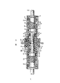
Figure 10 is the view that the part of the extra block of attachment device and adapter is cut open, has an attenuator element and is connected the ST connector plug assembly of each fixed position thereon;
Figure 11 and 12 is the stereographic maps that can be installed in the attenuator element that puts of adapter;
Figure 13 is mounted in the cross-sectional end view of the attenuator element that puts of adapter, and adapter is installed on the extra block;
Figure 14 is the front elevation of extra block.It is suitable for receiving a ST
Connector and the adapter that can be installed on the extra block and be suitable for receiving a FC connector.The FC connector just changes 180 ° from the installation site of itself and adapter among the figure; With
Figure 15 and 16 is the stereographic maps that are suitable for receiving the adapter of FC connector plug.
Referring now to Fig. 1 and 2,, their show the solid and the side view cutaway drawing of the electrical connector of representing with label 20 comprise attachment device, the joint connector of this electrical connector admittance ending connecting optical fiber.A joint connector or comprise AT﹠amp; The plug-assembly of the ST connector of T is depicted among Fig. 1, and it is by label 22 expressions.This plug-assembly is exemplary, and other plug-assembly also can comprise this device of the present invention.Each of two light transmitting fiber 21-21 to be connected comprises the glass core and the involucrum that are encapsulated in the canning, and this is known in the art.Light transmitting fiber can be encapsulated in the pipe 31 of a Polyvinylchloride (PVC), with provide a kind of can be according to the present invention by termination and the buffered fiber that is connected.Coupling arrangement of the present invention also can be used for connecting single fiber cable 30-30(and sees Fig. 1 again), what wherein cover pipe 31 is reinforcement 33, as the reinforcement made by aramid fiber material and the overcoat 35 that can be made up of PVC.
With reference to Fig. 1 and 2, can see that electrical connector 20 comprises plug-assembly on two, each is generally by label 22 expressions.The counter element of plug-assembly 22-22 is with identical labelled notation.Plug-assembly is to arrange like this, and promptly the longitudinal axis 38-38 of two assemblies is coaxial.Except an end of light transmitting fiber 21, each plug-assembly 22 comprises an optical fiber junction or plug 40, and it has passage 41(and sees Fig. 2) and by, for example a kind of glass, plastics or stupalith are made.The about 2.5mm of the external diameter of plug 40.The end face 39 of plug 40 comprises the opening of passage 41.Should be noted that in Fig. 2 shown assembly 22-22 partly is installed on the attachment device of the present invention, but not fixed thereon.
When optical cable 30 of termination, light transmitting fiber cladding system, and pipe 31, reinforcement 33 and overcoat 35 with plug 40 terminations before remove from an end of light transmitting fiber 21.Then the fibre-optic end that does not have to cover is inserted in the passage 41 of plug 40.The unlapped end of light transmitting fiber 21 is fixed in the passage 41 of plug 40, and for example, this fibre-optic end face is rived and polished.Another light transmitting fiber and plug-assembly repeat this process.
Each terminating set also comprises connector 42 or right cylinder (seeing Fig. 1 and 2), compression spring 44 and the tubular casing of being made by plastics or metal material of being made by plastics or metal material 45.Can see, plug 40, each all has circular xsect connector 42 and cover 45.Connector 42 comprises that one goes out and can insert the location that separates or the alignment keys 43 of the arbitrary position a plurality of positions from longitudinal axis 38 radial axles.
Each plug-assembly can also be provided with restriction cover 45 devices with respect to connector 42 admissible rotations.In order to achieve this end, this cover can comprise a pin; It inwardly stretches into (not shown) in the cam rail that the minor diameter 46 of connector is provided with from annular collar 48.
See Fig. 1 again, the groove 57 that extends on the groove 55 that cover 45 comprises a longitudinal extension, one end and circumference is communicated with.Forming groove 57 like this has a locking protuberance 58 so that limit the tubular wall of its shell.These grooves 55,57 and locking protuberance 58 are used for plug-assembly 22 is fixed on another part of electrical connector 20.
Complete plug-assembly 22 has optical cable support 59(to see Fig. 1), it extends along optical cable from overlapping 45, and is conical.This part of plug-assembly 22 alleviate the strain of optical cable and guarantee optical cable and the interconnection of other optical cable after in use can stand the bending of repetition, and do not have undue stress to be applied on this light transmitting fiber.
The light transmitting fiber that is connected with the ST connector can interconnect on a control panel.For example, referring now to Fig. 3, light transmitting fiber terminal block 60 has multiple arrangement.They are respectively applied for the fixing first group of ST connector plug that is connected with the input optical fiber (not shown) and fix second group of ST or FC connector plug, for example, their terminations output fiber channel (not shown), these devices are used for fixing connector plug in addition, between first group of connector and second group of corresponding connector light transmitting fiber are connected.Just as can be seen, comprise a plurality of aperture 62-62 on the connector breakout box 60.
In order to provide service, a plurality of junction boxes are provided to many users.In these junction boxes, one or more terminal block 60-60 supporting electrical connectors; This electrical connector is connected with fiber channel on house that extends to the user or the transmission equipment; Extending to optical cable on the terminal block has their each fiber on the connector on the terminal block of terminating to.Then, when requiring the user served, the output fiber channel that can extend into transmission equipment or extend to the user house is connected, so that this fiber channel is connected.
The device of fixing corresponding ST connector with the relation that connects comprises attachment device 20.Method of attachment on terminal block is based on to use and is called attachment device or equipment.This attachment device comprises that a plurality of extra block 70-70(see Fig. 3-5), these extra blocks are adapted to be mounted within on the terminal block 60.Therefore, each extra block 70 is suitable for partly passing one of a plurality of aperture 62-62 on the terminal block.
Briefly, a plurality of extra block 70-70 in a row is installed on the terminal block one by one.Can see in the Figure 4 and 5 that just in time each extra block 70 comprises middle body 72, a pair of radially relative plane 73-73 be arranged on it and threaded portion 75-75 is arranged.One side of middle body 72 is connected on the flange section 74, stretches out a tubular portion 76 on its opposite side.This tubular portion 76 comprises that a longitudinal extension leads to the keyway 78 of an end of tubular portion.This keyway one end opening.Two stop pin 79-79 extend radially out from the outside surface of tubular portion 76.As appreciable among Fig. 2, the figure shows the side cutaway view of extra block 70, inwall 81 separates tubular portion 76 and middle body 72.The opening 83 that is limited by the conical surface 85 of wall 81 is communicated with the inside of tubular portion 76 with the cavity 86 of middle body.
With reference now to Fig. 5,, can see that the flange section 74 of annular knurl comprises a ring portion 87, it has by otch 89 and the 90 extension 88-88 that interrupt.The end 91 of ring portion 87 and 92 is separated by block 94, and block is formed with location division 96 thereon.Surface 99 separates with extension 88 and partly covers thus.The flange end of extra block is suitable for receiving a label to be 100 light transmitting fiber adapter and to be fixed in position.
One of advantage of attachment device of the present invention is the method for two steps.It can be used for providing fabricated section for connector 22-22 on terminal block 60.At first, a plurality of relatively cheap extra block 70-70 can be installed on terminal block.Then, when requiring to serve, one or more adapters are installed on the selected extra block, so that the interconnection of input and output circuit.
With reference now to Fig. 6 and 7,, show the light transmitting fiber adapter 100 that is suitable on extra block 70, receiving and being suitable for receiving a ST connector.This adapter 100 comprises that first tubular portion or cover end 103, the second tubular portions 102 have the xsect of a ring-type, and comprises the stop pin 101-101 that radially extends relatively.First tubular portion 103 comprises hole 106, and this hole 106 is suitable for receiving the cover 107 of ST electrical connector.In most preferred embodiment, this cover is made by zirconia.For the cover that is suitable for providing attenuating device, the groove 108(that a longitudinal extension is led in this hole 106 sees Fig. 1-2).Cover 107 is arranged in the hole 106 and has one and puts groove 109(Fig. 1-2 of longitudinal extension at this).Inlet end at first tube of adapter 100 can guarantee to allow centring ring 110(to see Fig. 2) install within it.See Fig. 2 because the inner of first tubular portion terminates at the inwall 112(that the hole 106 and the cavity 114 of relevant connector plug end are separated) on, so, see Fig. 6 around the surperficial 111(of tubular portion 103 porch) and the effect of the centring ring 110 that is provided with is that cover 107 is fixed in the adapter.Cover 107 is fixed between wall 112 and the centring ring 110.Hole 106 is communicated with cavity 114 by an opening 116 that has a tapering part 118.
As shown in Figure 7, flange 104 comprises a flange portion 119,121,122 and lock parts 124 of leader.(see figure 8) when adapter 100 is inserted in wherein, leader 121 are suitable for being contained in the otch 89 and on plane 99, and leader 122 is suitable for being contained in the otch 90 of flange end of extra block 70.When adapter 100 rotated, leader 121,122 fitted into respectively in the groove 128,129 of flange portion 74.Along with leader 121,122 is contained in the groove 128,129, the sticking department 124 of leader 122 is seen Fig. 9 with ring portion 87 and block 94() a part engage.Adapter is inserted into like this, and the end 91 of ring portion 87 that makes leader 122 1 ends 126 leave the flange portion 74 of extra block 70 is provided with.See Fig. 9 again, when this adapter moved in the direction of the clock it by the skilled worker, the front end 126 of leader 122 was moved beyond otch 90, moved on to then between the plane 99 of extension 88 and extra block flange portion 74.Simultaneously, leader 121 is moved beyond otch 89 and leans against on another part of extension 88 of flange portion of link 92.The mobile fully lock part 124 rapid pintle hook locks that make of adapter are fixed on the extra block 70 with the adapter with fastening on location division 96.
When the plug of a connector when inserting the extra block end of relevant cover 107, its alignment keys 43 is aimed at the keyway 78 on the extra block.When alignment keys 43 when the keyway 78 of extra block moves, plug 40 inserts in this cover.Simultaneously, the stop pin 79-79 of extra block enters cover 45 groove 57-57 and groove 55-55 and moves along it.At the end that travels of plug 40, and when overlapping 45 when extra block rotates, each stop pin 79 is arranged on the back of locking protuberance 58.For an output fiber channel, the plug 40 of its joint connector inserts the adapter end of attachment devices 20 by keyway 43, and the key 43 of plug is contained in the keyway 131 of the adapter that plug packs into.Simultaneously, the stop pin 101-101 of adapter enters groove 57-57 and enters the groove 55-55 of plug-assembly then and move along these grooves, the back of the locking protuberance 58-58 that suitably moves the cover 45 that makes these stop pins 101-101 be arranged on second tube that is contained in adapter that realizes along with the skilled worker.Fig. 1 and 10 represents to have the attachment device of one or two plug-assembly 22-22 respectively, and they are separately fixed on the tube of second tube of adapter 100 and extra block.The orientation of Figure 10 is such, and promptly it can not show locking lock and relevant groove.
In order to obtain minimum loss, the plug 40-40 that it is desirable to be arranged in the cover 107 should make their longitudinal axis aim at and make the fiber end face contact with end face 39-39.Insert loss in order to obtain desirable decay, plug should make their longitudinal axis aim at and make the fiber end face with plug end face 39-39 contact (see figure 10) with an attenuator element 140.Comprise an attenuator though it should be noted that the coupling arrangement among Figure 10, do not comprise that in Fig. 2 the inside surface of the outside surface of each plug 40 and mantle cavity wall is the surface of mutual Matching Alignment; When the end of plug is contained in cover 107 the time, this surface can make plug enter the position of requirement.Aim at when being provided with cover 107 when element 140, plug should have desired end separating.
Match owing to attenuator element 140 with between overlapping 107, attenuator element 140 can longitudinally move in this cover.The ST connector is considered to a kind of unsteady design, and its interior two plugs are spring-loaded, and be positioned at adapter 100(and see Figure 10) a flexible opening sleeve align.When first plug 40 inserted extra block, this plug was crossed the cross central line of cover 107, and its is mobile because the front end of the major diameter part 51 of connection body is static with being connected of wall 81 of extra block.When second plug was connected to opposite side on this adapter and two plugs and contacts with attenuator element, first plug was pushed rearward, when the elastic load between two plugs that provided by compression spring 44-44 obtains balance till.
Therefore, during attenuator element between the fiber end face that one of design is placed on two plugs, people must both prevent that first plug from crossing the center line of cover, provide a device for the attenuating elements that moves with plug again.The method that solves the latter is by an attenuator disk by a guide supporting is used for attenuator element 140.When the ST connector plug inserted, this attenuator can be suspended on its discoid bar in the cover, and its neck passes this groove that puts and its head also is arranged in the groove so that move along it.
It should be noted that attachment device of the present invention also can be used for the mixing connection of FC to the ST connector.See Figure 14 now, a FC is to the ST electrical connector in label 149 expressions.Advantageously, identical extra block 70 be used for the ST connector to ST connector and ST connector to the FC electrical connector.
Present ginseng person Figure 14-16, shown adapter 150 is suitable for being contained in the extra block 70, and is suitable for receiving a FC connector plug.A ST connector plug 40 the same can being contained in the tube 76 of extra block 70 as previously described.Device among Figure 14 comprises a part, promptly Figure 14 shown in right hand portion, this part is similar to the counterpart in Fig. 2 and 10.Adapter 150 comprises a central flange part 154 that is similar to the flange 104 of adapter 100.Adapter 150 also comprises 152, one connector plug ends 153 of a tubulated ends and flange 154.Tubulated ends 152 has a circular slot cross-section.It comprises a hole 156 that step is arranged, and this hole is fit to receive a cover 107.The groove 158(that longitudinal extension is led in hole 156 sees Figure 14).When this adapter comprises an attenuator element, and overlap 107 when being arranged in the hole 156, the groove 109 that puts longitudinal extension is aimed at groove 158.Adapter 150 comprises male thread portion 161, and a keyway 174 and an annular lug boss 164 that has an inlet portion 165 from its free end extension arranged on it.The external diameter of lug boss 164 is less than the internal diameter of the threaded portion 161 of connector plug end 153, so that an annulus 167 to be provided.
A fiber that is connected on another fiber by a FC device passes through a plug-assembly 180(Figure 14) termination.Plug-assembly 180 comprises the columniform plug or the joint 182 of a termination fiber.This plug 182 is contained in connector or the cylinder 184, and cylinder 184 is contained in the female cover 186.Cover 186 be suitable for move slidably on the cylinder 184 and threaded portion 161 at FC adapter 150 on rotate spirally.Cylinder and plug are by the outside bias voltage of spring.Cylinder 184 also comprises a key 192 in the keyway 174 that is suitable for being contained in thread head 161.It should be noted that the plug-assembly shown in Figure 14 has rotated 180 ° from the position with the adapter installation, so that expression key 192.
When requiring to connect, the skilled worker makes key 192 aim at keyway 174, and the plug 182 of plug-assembly is arranged in the cover 107, if an attenuator element is bearing in this cover, then plug 182 can contact with attenuator element 140.When rotating spirally on cover 186 the thread heads 161 at adapter, cylinder moves on lug boss 164 slidably.
No matter be the plug that inserts the FC connector part, still the plug that inserts the ST connector part all makes the arbitrary plug in the two engage with the disk of attenuator element 140, if use attenuator element, this element comprises head and neck and is hung by track, this element is moved along the direction of cover.Another that inserts that another plug can make its disk that engages attenuator element be the surface mainly, and this disk is moved by opposite direction, reaches its link position up to this another plug.Obviously, the excess of stroke of ST connector plug 40 adds half plane of not answering extend through to be represented by label 190 that half length that gets on the right track deducts the disc thickness of attenuator element 140 again.Otherwise as shown in figure 14, the adjacency section of the track on the end of the groove 158 in the cavity 156 and an end of adapter 150 may cause the damage of element 140 or disturb the cylinder 184 of FC plug-assembly 180.
Claims (10)
1, a kind of optical fiber coupler device, it comprises two plug-assemblies, and each plug-assembly comprises that connects a fibre-optic plug, and at least one plug-assembly comprises a key, and described electrical connector is characterized in that:
Extra block is suitable for being installed on the aperture of terminal block, described extra block comprises tube, this tube has the keyway of the longitudinal extension that forms on its wall, this keyway extends from the flange end, this flange end comprises guiding and locking device, and described extra block comprises first and second cavitys, and these two cavitys interconnect by the opening on the wall of interior setting, make described first cavity lead to the flange end of described extra block, the end opposite of described extra block is led in second chamber;
Adapter, it comprises the first and second coaxillay aligned tubes, two tubes extend from a flange part with opposite direction, this flange part comprises and is suitable for the device that matches with the guiding and the locking device of described extra block, so that when between described adapter and extra block, suitable relative motion taking place adapter is fixed on the extra block, first tube is suitable for being contained in first cavity of described extra block, and second tube comprises one of them the fixing device within it that makes the above-mentioned plug that inserts second tube; And
On first tube that is arranged on described adapter and be suitable at one end holding one of them the cover of an end of described plug, this plug is arranged in the tube of described extra block, and in its opposite end, described another plug is arranged in second tube of described adapter, so that forming photoconduction by described two plugs between the light transmitting fiber of termination connects, described cover is included in the groove of longitudinal extension on its wall and when the described plug of described at least one plug-assembly is installed in the tube of described extra block, and the key of described at least one plug-assembly is installed in the keyway of tube of described extra block.
2, optical fiber coupler device as claimed in claim 1, it is characterized in that: described adapter and described extra block are to install like this, promptly between the first and second different mutually plug-assemblies, form and connect, there is screw thread the second tube outside of wherein said adapter and round the lug boss of a plug that is suitable for installing described second plug-assembly and be spaced from the coaxial setting in ground, the keyway of the longitudinal extension of the tube of wherein said extra block is suitable for installing the key that radially extends from connector, the plug of described first plug-assembly is installed on the connector, the described tube of described extra block comprises two just in time on the contrary from the pin of that extension, so that hold in the lock slots of overcoat of the connector that described first plug-assembly is installed within it.
3, optical fiber coupler device as claimed in claim 1, it is characterized in that: second tube of the tube of described adapter comprises one section threaded outside and the coaxial internal projection portion that is arranged in the described outside and is spaced from, wherein, the tube of described extra block comprises keyway and two stop pins that the diametric(al) of stretching out from its outside surface is opposite of longitudinal extension thereon, described two plug-assemblies comprise first and second plug-assemblies
Second assembly of described plug-assembly comprises a slotting shape that stretches out from connector, in the plug of described second plug-assembly is contained in second tube of described adapter and when being contained in the described cover, this connector is suitable for being centered around the described lug boss setting of second tube of described adapter, and comprise an overcoat, there is screw thread this overcoat inside and moves slidably, when the described plug of described second plug-assembly was installed in the described cover, this is outer to be enclosed within on the described outside of described second tube of described adapter and to rotate spirally;
First plug-assembly of described plug-assembly comprises a connector that is extended with a plug, the described connector of described first plug-assembly has one from that key that stretches out, be contained in the tube of described extra block with the described plug of described first plug-assembly of box lunch and in the described cover time, this key is installed in the keyway of described extra block, described first assembly of described plug-assembly also comprises an overcoat, this overcoat centers at least a portion setting of described connector coaxially and comprises two cam paths and the lock slots that is associated, described key is accommodated in the keyway of described extra block so that the plug of described first plug-assembly inserts in the described cover, the described pin of described each extra block moves and is installed in the lock slots that links to each other therewith along cam path, so that described outer the putting of first plug-assembly on the tube of described extra block lived and be fixed on to pintle hook lock, wherein, described first plug-assembly comprises the compression spring that is provided with around its described connector, and described second plug-assembly comprises its plug biased elastic device outside described second plug-assembly.
But the described optical fiber coupler device of 4 claims 1 is characterized in that it comprises:
First plug-assembly that one cannon plug is arranged;
Second plug-assembly that one cannon plug is arranged, each plug of each described plug-assembly has by the passage in it, and being suitable for the interior light transmitting fiber of overcoat that termination is arranged on this passage and the above-mentioned plug part of sealing, described first plug-assembly comprises the device of the described plug of the outside bias voltage of the direction that is used for from the fiber entry end towards its opposite end;
Wherein, the guide piece of described extra block is the guide piece of annular; And
Described adapter comprises the outstanding device that cooperates with the annular guide piece and the locking device of described extra block, and when occurring suitable relatively rotating between described adapter and the described extra block, it is fixed on described adapter on the described extra block;
First tube of described adapter is suitable for being contained in first cavity of described extra block, and described second tube comprises vertical keyway, when described adapter is fixed on the described extra block, it is vertically aimed at the described keyway on the tube of described extra block, the overcoat of described second plug-assembly is suitable for being fixed on the end of second tube of described adapter, and this overcoat of described first plug-assembly is suitable for being fixed on the end of tube of described extra block.
5, optical fiber coupler device as claimed in claim 4, it is characterized in that: the outstanding device of described adapter comprise one have one roughly can be towards the longitudinal axis of described adapter radially to the teat of the end of intrinsic deflection, this teat is adapted to be mounted between the surface of described flange end of the extension of described guide piece and described extra block, insert described extra block and when rotating, described teat kayser is gone into a fixing position with first tube of the described adapter of box lunch.
6, optical fiber coupler device as claimed in claim 4, it is characterized in that, the flange portion of described adapter comprises having towards this adapter longitudinal axis radially to the locking protuberance of intrinsic deflection and the protuberance that leads, when producing relative rotation between above-mentioned extra block and the adapter, each this protuberance is contained between the surface of the extension of above-mentioned circular guide piece and above-mentioned extra block flange end, this surface and above-mentioned extension separate, above-mentioned locking protuberance has a free end, when the part of above-mentioned each protuberance is contained in above-mentioned extension and the above-mentioned surface, this free end is suitable for being locked on the fixed position rapidly.
7, optical fiber coupler device as claimed in claim 4, it is characterized in that: described each plug-assembly comprises an overcoat that has the flange that a ring-type inwardly stretches out, the connector that is arranged on the place, plug one end of described each plug-assembly passes through this flange, described connector has the end of one section increase, the end of this increase is positioned at the described end of described plug, each described plug-assembly also comprises around the stop collar and the compression spring of described connector and close described flange inner setting, this compression spring around described connector setting and with the interior side engagement of the described augmenting portion of the outside of described flange and described connector, so that with described stop collar with connector and plug to extrapolation, described plug is remained in the described overcoat, and described connector also comprises from its described augmenting portion and extending radially out and key fixed thereon;
When the key of the described connector of described first plug-assembly is arranged in the tube of described extra block when the described plug of described first plug-assembly, be suitable for being arranged in the keyway of described extra block, and the described key of the connector of described second plug-assembly is suitable for being arranged in the keyway of second tube of described adapter; Wherein, second tube of the tube of described extra block and described adapter comprises that respectively two extend radially out and the opposite pin of diametric(al) from described extra block with from described adapter, this pin is suitable for holding and the outer of connector is housed within it puts in the set lock slots, so that described plug-assembly is fixed on described extra block and the described adapter, and prevent that accidental between the overcoat of the described tube of described extra block and described first plug-assembly from rotating and the described tubular portion of described adapter and be fixed on rotation between that the described overcoat of described second plug-assembly, wherein, each described overcoat comprises two just in time opposite cam paths, the free end of each groove around described overcoat from described cover inwardly extends spirally, each cam path and relevant lock slots connection, direction by the longitudinal axis that is parallel to described plug stretches out and relevant lock slots is from the inner of relevant cam path, each described overcoat also is provided with the just in time opposite inlet of diametric(al), outer end at free-ended each described inlet of described overcoat cam path relevant with is communicated with, second tubulated ends of described adapter comprises the keyway of longitudinal extension, this keyway extends from the inlet end of described second tubulated ends, and the stop pin that a pair of diametric(al) is just in time opposite is protruding from described second tube, described pin and described keyway are such, promptly when the overcoat of a plug-assembly and described adapter on time, described keyway on second tubular tip of the key on its plug-assembly and described shell is aimed at, the pin of described adapter is aimed at the cam path of described overcoat, and described stop pin and described keyway also are suitable for moving into described flange groove and described lock slots along described inlet, so that described plug-assembly is fixed on the described adapter.
8, optical fiber coupler device as claimed in claim 1 is characterized in that, it comprises an attenuating elements, and this attenuating elements comprises the tabular part of being made by the refractive index materials that roughly is equal to glass, guide rail and suspended portion; Guide rail comprises a suspended portion that supports described tabular part, described suspended portion is installed in the described groove of described cover, and described plate portion is arranged in the described cover, the part of described guide rail is in abutting connection with the outside surface setting of described cover, described attenuating elements can move with longitudinal sliding along described cover when each described plug inserts described cover, and described element engages with each described plug in the time of in described edge connector drops on described cover.
9, light transmitting fiber coupling arrangement as claimed in claim 8, it is characterized in that, it comprises first and second plug-assemblies, wherein, in described described first tube that is set on described adapter, second tube of described adapter comprises one section threaded outside of outside car and a coaxial inner flange portion that is arranged in the described outside and is spaced from, wherein, the relative tubulated ends of described extra block comprises tube and two stop pins that the diametric(al) of stretching out from its surface is just in time opposite that have the keyway of a longitudinal extension on it;
Second assembly of described plug-assembly comprises a plug that stretches out from a connector, when described second plug-assembly is installed in the described cover, connector is suitable for around the described lug boss setting of the second end of described adapter, comprise that also one is slidably moved, the threaded overcoat of inner car, this overcoat can rotations spirally on the described outside of described second tube of described adapter when the plug of described second plug-assembly is installed in the described cover; And
First assembly of described plug-assembly comprises a connector that extends a plug, the connector of described first plug-assembly has the key that stretches out from it, when described first plug-assembly is installed in the described cover, this key is contained in the described keyway of described tube of described extra block, first assembly of described plug-assembly also comprises round the coaxial setting of at least a portion of described connector and comprises two cam paths and the overcoat of relevant lock slots, so that the plug of described first plug-assembly inserts in the described cover, and described key is placed in the keyway of described extra block, each pin of described extra block moves and is positioned in the relative lock slots along cam path, so that be fixed on the described overcoat of first plug-assembly of being fixed on the described extra block, wherein, described first plug-assembly comprises round the set compression spring of its described connector, and described second plug-assembly comprises the described first plug biased elastic device outside described second plug-assembly with it.
10, a kind of fibre-optic attachment device that connects by the plug connection of the first and second fibre-optic plug assemblies, described attachment device comprises:
Extra block, it is adapted to be mounted within the perforate on the terminal block and is suitable for having a plug-assembly that is connected to the there, described extra block comprises tube, this tube is formed with keyway from flange end longitudinal extension at Qi Bishang, this flange end comprises guiding and locking device, described extra block comprises first and second cavitys, they are interconnected by the opening on the wall of inside setting, make first cavity lead to the flange end of described extra block, described second cavity leads to another opposite end of described extra block.
Adapter, it comprises coaxillay aligned first and second tubes, first and second tubes extend by opposite direction from a flange part, this flange part comprises and is suitable for the stationary installation that matches with the guiding and the locking device of described extra block, when occurring suitable relative rotation motion of driving system between described adapter of box lunch and the described extra block, described adapter is fixed on the described extra block, described first tube is suitable for being installed in described first cavity of described extra block, described second tube comprises stationary installation, this stationary installation make plug-assembly mounted thereto be fixed, preventing unconscious rotational motion, and
This is set on one cover first tube of described adapter and is suitable for being installed on the plug ends of an adapter assembly with the one end, this plug-assembly is arranged in the tube of described extra block, and another plug of its end opposite is arranged in second tube of described adapter, so that forming a kind of photoconduction between the light transmitting fiber that head end connects and connecting by broadcasting, described cover is included in the groove of longitudinal extension on its wall, the described vertical keyway of described extra block and the stationary installation of described adapter match with the several sections of the described plug-assembly that is installed in that, prevent the unconscious rotation of described plug-assembly.
Applications Claiming Priority (2)
| Application Number | Priority Date | Filing Date | Title |
|---|---|---|---|
| US07/598,497 US5067783A (en) | 1990-10-16 | 1990-10-16 | Optical fiber connector buildout system |
| US598,497 | 1990-10-16 |
Publications (2)
| Publication Number | Publication Date |
|---|---|
| CN1060911A CN1060911A (en) | 1992-05-06 |
| CN1029038C true CN1029038C (en) | 1995-06-21 |
Family
ID=24395785
Family Applications (1)
| Application Number | Title | Priority Date | Filing Date |
|---|---|---|---|
| CN91109669A Expired - Fee Related CN1029038C (en) | 1990-10-16 | 1991-10-08 | Optical fiber connector buildout system |
Country Status (12)
| Country | Link |
|---|---|
| US (1) | US5067783A (en) |
| EP (1) | EP0481642B1 (en) |
| JP (1) | JPH0750229B2 (en) |
| KR (1) | KR100239096B1 (en) |
| CN (1) | CN1029038C (en) |
| AU (1) | AU631076B2 (en) |
| CA (1) | CA2050355C (en) |
| DE (1) | DE69128450T2 (en) |
| DK (1) | DK0481642T3 (en) |
| ES (1) | ES2110432T3 (en) |
| MX (1) | MX174463B (en) |
| TW (1) | TW231339B (en) |
Families Citing this family (85)
| Publication number | Priority date | Publication date | Assignee | Title |
|---|---|---|---|---|
| US5274729A (en) * | 1992-07-30 | 1993-12-28 | At&T Bell Laboratories | Universal optical fiber buildout system |
| US5367594A (en) * | 1992-09-01 | 1994-11-22 | The Whitaker Corporation | Fiber optic splicer-connector |
| US5384885A (en) * | 1993-10-28 | 1995-01-24 | At&T Corp. | Variable attenuation optical fiber coupling |
| US5408557A (en) * | 1994-04-20 | 1995-04-18 | Hsu; Chung-Tang | FC-type optical fiber cable connector's adaptor |
| IT1271222B (en) * | 1994-09-28 | 1997-05-27 | Sirti Spa | OPTICAL FILTER FOR TELECOMMUNICATIONS |
| CH689702A5 (en) * | 1995-11-17 | 1999-08-31 | Diamond Sa | Coupling component for optical connector e.g. for optical cable connected to sealed apparatus housing |
| US5687268A (en) * | 1995-11-27 | 1997-11-11 | Lucent Technologies Inc. | Pivotable optical shutter for blocking emission from a lightguide adapter #5 |
| US6045270A (en) | 1995-12-22 | 2000-04-04 | Methode Electronics, Inc. | Massive parallel optical interconnect system |
| US5680494A (en) * | 1996-05-16 | 1997-10-21 | Bell Atlantic Network Services, Inc. | FC-type optical fiber connector adapter |
| DE19626036A1 (en) * | 1996-06-28 | 1998-01-02 | Whitaker Corp | Optical connector |
| JP3066739B2 (en) * | 1996-07-15 | 2000-07-17 | セイコーインスツルメンツ株式会社 | General-purpose optical connector and basic plug |
| US5778121A (en) * | 1996-11-05 | 1998-07-07 | Itt Corporation | Connector with optic fiber terminal |
| US5937121A (en) * | 1997-01-03 | 1999-08-10 | The Siemon Company | Adapters for coupling optical fiber |
| US5896477A (en) * | 1997-05-16 | 1999-04-20 | Lucent Technologies Inc. | Optical fiber coupling buildout system |
| US5838855A (en) * | 1997-05-16 | 1998-11-17 | Lucent Technologies Inc. | Sleeve housing for optical coupling buildout |
| US5930425A (en) * | 1998-04-21 | 1999-07-27 | Lucent Technologies Inc. | High density coupling module |
| US6196729B1 (en) * | 1998-09-04 | 2001-03-06 | Lucent Technologies Inc. | Apparatus for retaining an attenuator element |
| US6149315A (en) * | 1998-09-04 | 2000-11-21 | Lucent Technologies Inc. | Side load resistant buildout |
| US6220763B1 (en) | 1998-09-04 | 2001-04-24 | Lucent Technologies Inc. | Optical fiber buildout system |
| US6188827B1 (en) * | 1998-09-04 | 2001-02-13 | Lucent Technologies Inc. | Attenuator element for a buildout system |
| US6334715B1 (en) * | 1998-12-24 | 2002-01-01 | Bti, Photonics, Inc. | Mountable optical fibre couplers |
| US6524014B2 (en) * | 1999-04-01 | 2003-02-25 | Fitel Usa Corp. | Universal modular optical fiber buildout |
| EP1041413A1 (en) * | 1999-04-01 | 2000-10-04 | Lucent Technologies Inc. | Universal snap-fit buildout base and mounting panel system |
| US6253017B1 (en) * | 1999-08-04 | 2001-06-26 | Delphi Technologies, Inc. | Fiber optic connector with optical attenuator |
| US6367984B1 (en) | 1999-11-10 | 2002-04-09 | Lucent Technologies, Inc. | Optical fiber adapter |
| US6275643B1 (en) | 2000-02-09 | 2001-08-14 | Lucent Technologies, Inc. | Attenuator element for use with an optical fiber adapter |
| US6443629B1 (en) | 2000-02-22 | 2002-09-03 | Itt Manufacturing Enterprises, Inc. | Terminus body with trapped spring |
| US6364534B1 (en) | 2000-02-29 | 2002-04-02 | Lucent Technologies, Inc. | Panel mounting assembly for optical fiber connectors |
| US6508593B1 (en) * | 2000-05-09 | 2003-01-21 | Molex Incorporated | Universal panel mount system for fiber optic connecting devices |
| US6685361B1 (en) * | 2000-06-15 | 2004-02-03 | Weatherford/Lamb, Inc. | Fiber optic cable connectors for downhole applications |
| US6461055B1 (en) | 2001-04-11 | 2002-10-08 | Adc Telecommunications, Inc. | Fiber optic adapter with attenuator and method |
| US6609837B2 (en) | 2001-04-27 | 2003-08-26 | Fitel Usa Corp. | Optical fiber adapter for dissimilar size ferrules |
| US6616462B2 (en) * | 2001-09-04 | 2003-09-09 | Tonami Electronics Corporation | Convertible multi-diameter sleeve for optical fiber connectors |
| US7837658B2 (en) | 2001-11-13 | 2010-11-23 | Nypro Inc. | Anti-drawback medical valve |
| US7753892B2 (en) * | 2001-11-13 | 2010-07-13 | Nypro Inc. | Anti-drawback medical valve |
| DE10219935A1 (en) | 2002-05-03 | 2003-11-27 | Krone Gmbh | Device for an optical fiber connection |
| JP3483872B2 (en) * | 2002-05-22 | 2004-01-06 | 米沢電線株式会社 | Optical connector |
| US7108430B2 (en) * | 2003-02-21 | 2006-09-19 | Itt Manufacturing Enterprises, Inc. | Optic fiber terminus indexer |
| US7011454B2 (en) * | 2003-08-25 | 2006-03-14 | Panduit Corp. | Reversible fiber optic stub fiber connector |
| US7264402B2 (en) * | 2005-03-10 | 2007-09-04 | Corning Cable Systems Llc | Multi-fiber optic receptacle and plug assembly |
| JP2008009078A (en) * | 2006-06-28 | 2008-01-17 | Fujitsu Ltd | Optical receptacle |
| FR2911615B1 (en) * | 2007-01-18 | 2011-11-25 | Custon Laminates Mfg | MATERIALS FOR THE CONFECTION OF SAILS AND SAILS MADE WITH THIS TYPE OF MATERIALS. |
| US7758389B2 (en) * | 2008-01-25 | 2010-07-20 | Tyco Electronics Corporation | Connector assembly having a movable plug |
| MX2011002086A (en) | 2008-08-27 | 2011-03-29 | Adc Telecommunications Inc | Fiber optic adapter with integrally molded ferrule alignment structure. |
| JP5448885B2 (en) * | 2010-01-28 | 2014-03-19 | 富士フイルム株式会社 | Medical equipment and endoscope device |
| EP2354824A1 (en) * | 2010-01-29 | 2011-08-10 | CCS Technology Inc. | Hybrid connector |
| CN102109643B (en) * | 2011-02-18 | 2012-05-02 | 深圳市特发信息光网科技股份有限公司 | Optical fiber quick coupling and splicing method thereof |
| US9052468B2 (en) | 2011-03-04 | 2015-06-09 | Corning Cable Systems Llc | Fiber optic adapter mount |
| TW201239434A (en) * | 2011-03-24 | 2012-10-01 | Netgami System Llc | Multi-diameter optical fiber link for transmitting unidirectional signals and eliminating signal deterioration |
| US8686289B2 (en) * | 2011-07-14 | 2014-04-01 | Channell Commercial Corporation | Sealing mechanism and method for drop cable splice enclosures |
| US9110266B2 (en) | 2011-07-29 | 2015-08-18 | Corning Cable Systems Llc | Fiber optic cables seal and/or strain relief members, and related assemblies and methods |
| US8842962B2 (en) * | 2012-01-27 | 2014-09-23 | Corning Cable Systems Llc | Fiber optic cable strain relief device and method |
| US9122020B2 (en) * | 2012-06-06 | 2015-09-01 | Tyco Electronics Corporation | Connector assembly having a slidable connector |
| US9081152B2 (en) | 2012-08-30 | 2015-07-14 | Adc Telecommunications, Inc. | Adapter pack with removable sleeves |
| US9146362B2 (en) | 2012-09-21 | 2015-09-29 | Adc Telecommunications, Inc. | Insertion and removal tool for a fiber optic ferrule alignment sleeve |
| ES2606755T3 (en) | 2012-10-26 | 2017-03-27 | Ccs Technology, Inc. | Cable strain relief device and fiber optic distribution device |
| US9488793B2 (en) | 2013-09-10 | 2016-11-08 | Corning Optical Communications LLC | Combined optical fiber and power cable |
| JP5977459B2 (en) | 2013-11-12 | 2016-08-24 | ▲ホア▼▲ウェイ▼技術有限公司Huawei Technologies Co.,Ltd. | Fiber optic joint, fiber optic adapter, and fiber optic connector |
| US9551598B2 (en) | 2014-05-12 | 2017-01-24 | Siemens Energy, Inc. | Fiber optic sensing apparatus with an improved fiber-affixing device |
| AU2016263337A1 (en) | 2015-05-15 | 2018-01-04 | Adc Telecommunications (Shanghai) Distribution Co., Ltd. | Alignment sleeve assembly and optical fibre adapter |
| JP6337048B2 (en) * | 2016-07-21 | 2018-06-06 | ▲ホア▼▲ウェイ▼技術有限公司Huawei Technologies Co.,Ltd. | Fiber optic joint, fiber optic adapter, and fiber optic connector |
| CN109642992B (en) | 2016-09-30 | 2021-10-15 | 华为技术有限公司 | Optical fiber connector, optical fiber adapter and optical fiber connector |
| FR3066861B1 (en) * | 2017-05-23 | 2020-10-30 | Axon Cable Sa | COMPACT QUART-TURN CONNECTOR |
| US11300746B2 (en) | 2017-06-28 | 2022-04-12 | Corning Research & Development Corporation | Fiber optic port module inserts, assemblies and methods of making the same |
| US11668890B2 (en) | 2017-06-28 | 2023-06-06 | Corning Research & Development Corporation | Multiports and other devices having optical connection ports with securing features and methods of making the same |
| US11187859B2 (en) | 2017-06-28 | 2021-11-30 | Corning Research & Development Corporation | Fiber optic connectors and methods of making the same |
| US10359577B2 (en) | 2017-06-28 | 2019-07-23 | Corning Research & Development Corporation | Multiports and optical connectors with rotationally discrete locking and keying features |
| EP3646083A1 (en) * | 2017-06-28 | 2020-05-06 | Corning Research & Development Corporation | Fiber optic extender ports, assemblies and methods of making the same |
| HRP20230219T1 (en) * | 2017-06-28 | 2023-04-14 | Corning Research & Development Corporation | Compact fiber optic connectors having multiple connector footprints, along with cable assemblies and methods of making the same |
| CN107401246A (en) * | 2017-09-12 | 2017-11-28 | 长春工程学院 | A kind of assembled interior wall partition |
| KR102176323B1 (en) * | 2018-09-12 | 2020-11-09 | 박상미 | Manufacturing apparatus of vinyl bag |
| US10641967B1 (en) | 2018-11-16 | 2020-05-05 | Corning Research & Development Corporation | Multiport assemblies including a modular adapter support array |
| US10768382B2 (en) | 2018-11-29 | 2020-09-08 | Corning Research & Development Corporation | Multiport assemblies including access apertures and a release tool |
| US11294133B2 (en) | 2019-07-31 | 2022-04-05 | Corning Research & Development Corporation | Fiber optic networks using multiports and cable assemblies with cable-to-connector orientation |
| US11487073B2 (en) | 2019-09-30 | 2022-11-01 | Corning Research & Development Corporation | Cable input devices having an integrated locking feature and assemblies using the cable input devices |
| EP3805827A1 (en) | 2019-10-07 | 2021-04-14 | Corning Research & Development Corporation | Fiber optic terminals and fiber optic networks having variable ratio couplers |
| US11650388B2 (en) | 2019-11-14 | 2023-05-16 | Corning Research & Development Corporation | Fiber optic networks having a self-supporting optical terminal and methods of installing the optical terminal |
| US11536921B2 (en) | 2020-02-11 | 2022-12-27 | Corning Research & Development Corporation | Fiber optic terminals having one or more loopback assemblies |
| US11604320B2 (en) | 2020-09-30 | 2023-03-14 | Corning Research & Development Corporation | Connector assemblies for telecommunication enclosures |
| US11927810B2 (en) | 2020-11-30 | 2024-03-12 | Corning Research & Development Corporation | Fiber optic adapter assemblies including a conversion housing and a release member |
| US11880076B2 (en) | 2020-11-30 | 2024-01-23 | Corning Research & Development Corporation | Fiber optic adapter assemblies including a conversion housing and a release housing |
| US11686913B2 (en) | 2020-11-30 | 2023-06-27 | Corning Research & Development Corporation | Fiber optic cable assemblies and connector assemblies having a crimp ring and crimp body and methods of fabricating the same |
| CN113031169B (en) * | 2021-05-26 | 2021-08-31 | 中天宽带技术有限公司 | Prefabricated connector, coupler and prefabricated connector assembly |
| US11947167B2 (en) | 2021-05-26 | 2024-04-02 | Corning Research & Development Corporation | Fiber optic terminals and tools and methods for adjusting a split ratio of a fiber optic terminal |
| US20230417999A1 (en) * | 2022-06-24 | 2023-12-28 | Acon Optics Communications Inc. | Optical-fiber connector with a protective cap and standard connector |
Family Cites Families (7)
| Publication number | Priority date | Publication date | Assignee | Title |
|---|---|---|---|---|
| US4934785A (en) * | 1983-08-29 | 1990-06-19 | American Telephone And Telegraph Company | Optical fiber connector |
| US4717234A (en) * | 1986-03-20 | 1988-01-05 | Gte Products Corporation | In-line optical attenuators |
| US4880291A (en) * | 1988-02-04 | 1989-11-14 | American Telephone & Telegraph Company, At&T Bell Laboratories | Optical fiber connector and methods of making |
| US4834486A (en) * | 1988-04-21 | 1989-05-30 | Siecor Corporation | Connector sleeve adapter |
| DE8806647U1 (en) * | 1988-05-20 | 1988-08-04 | Standard Elektrik Lorenz Ag, 7000 Stuttgart, De | |
| US4900124A (en) * | 1988-12-12 | 1990-02-13 | American Telephone & Telegraph Company, At&T Bell Laboratories | Biconic optical fiber connecting device having attenuator |
| DE8906127U1 (en) * | 1989-05-18 | 1989-07-13 | Siemens Ag, 1000 Berlin Und 8000 Muenchen, De |
-
1990
- 1990-10-16 US US07/598,497 patent/US5067783A/en not_active Expired - Lifetime
-
1991
- 1991-08-30 CA CA002050355A patent/CA2050355C/en not_active Expired - Fee Related
- 1991-09-10 TW TW080107167A patent/TW231339B/zh active
- 1991-10-07 ES ES91309161T patent/ES2110432T3/en not_active Expired - Lifetime
- 1991-10-07 DE DE69128450T patent/DE69128450T2/en not_active Expired - Lifetime
- 1991-10-07 EP EP91309161A patent/EP0481642B1/en not_active Expired - Lifetime
- 1991-10-07 DK DK91309161T patent/DK0481642T3/en active
- 1991-10-08 CN CN91109669A patent/CN1029038C/en not_active Expired - Fee Related
- 1991-10-08 AU AU85690/91A patent/AU631076B2/en not_active Ceased
- 1991-10-15 MX MX9101600A patent/MX174463B/en not_active IP Right Cessation
- 1991-10-15 KR KR1019910018079A patent/KR100239096B1/en not_active IP Right Cessation
- 1991-10-16 JP JP3294770A patent/JPH0750229B2/en not_active Expired - Fee Related
Also Published As
| Publication number | Publication date |
|---|---|
| KR920008512A (en) | 1992-05-28 |
| EP0481642B1 (en) | 1997-12-17 |
| US5067783A (en) | 1991-11-26 |
| MX174463B (en) | 1994-05-17 |
| EP0481642A3 (en) | 1992-09-09 |
| DK0481642T3 (en) | 1998-08-24 |
| CA2050355C (en) | 1995-02-21 |
| JPH04289805A (en) | 1992-10-14 |
| AU631076B2 (en) | 1992-11-12 |
| DE69128450D1 (en) | 1998-01-29 |
| ES2110432T3 (en) | 1998-02-16 |
| DE69128450T2 (en) | 1998-04-16 |
| JPH0750229B2 (en) | 1995-05-31 |
| EP0481642A2 (en) | 1992-04-22 |
| KR100239096B1 (en) | 2000-01-15 |
| TW231339B (en) | 1994-10-01 |
| AU8569091A (en) | 1992-04-30 |
| CN1060911A (en) | 1992-05-06 |
Similar Documents
| Publication | Publication Date | Title |
|---|---|---|
| CN1029038C (en) | Optical fiber connector buildout system | |
| CA1311383C (en) | Optical fiber connector | |
| KR960013797B1 (en) | Optical fiber connector | |
| US4258977A (en) | Optical fibre connector | |
| US7460750B2 (en) | Expanded beam, single fiber, fiber optic connector | |
| CN1034886C (en) | Optical fiber connector having provisons for interconnection and for prevention of optical and mechanical disconnection | |
| US3948582A (en) | Optical fibre connector | |
| US4880291A (en) | Optical fiber connector and methods of making | |
| US4881792A (en) | Self-adjusting optical fiber connector assembly | |
| WO2009113819A1 (en) | Optical adapter combined with optical fiber | |
| CN101065698A (en) | Fiber optic drop cables and preconnectorized assemblies having toning portions | |
| US4852963A (en) | Optical fiber biconic connector | |
| US4605281A (en) | Self-aligning fiber optic connector | |
| WO2022100572A1 (en) | Connector assembly, optical fiber connection joint, optical fiber connector and prefabricated optical cable | |
| US11474303B2 (en) | Optical connector ferrule, sleeve, and method for manufacturing ferrule member | |
| US4707068A (en) | Optical fiber waveguide connector system | |
| US9651755B2 (en) | Fiber optic interconnect systems and methods | |
| CN212031784U (en) | System for polarity connection between fiber optic adapter and fiber optic connector | |
| CN110854635B (en) | Photoelectric separation connecting device | |
| US7025508B2 (en) | Optical short-circuit insert and optical short-circuit plug | |
| CN206863280U (en) | A kind of multichannel bandwidth fiber optic connector | |
| TWM605933U (en) | Duplex optical fiber adapter | |
| TWM602745U (en) | Coaxial cable connector system | |
| TWM604083U (en) | Same-direction polarity interchange adapter | |
| CN219456567U (en) | High-precision optical fiber |
Legal Events
| Date | Code | Title | Description |
|---|---|---|---|
| C06 | Publication | ||
| PB01 | Publication | ||
| C10 | Entry into substantive examination | ||
| SE01 | Entry into force of request for substantive examination | ||
| C14 | Grant of patent or utility model | ||
| GR01 | Patent grant | ||
| C15 | Extension of patent right duration from 15 to 20 years for appl. with date before 31.12.1992 and still valid on 11.12.2001 (patent law change 1993) | ||
| OR01 | Other related matters | ||
| C17 | Cessation of patent right | ||
| CF01 | Termination of patent right due to non-payment of annual fee |
Granted publication date: 19950621 Termination date: 20101008 |